Note: Descriptions are shown in the official language in which they were submitted.
WO 2019/018740 PCT/US2018/043047
SYSTEM AND METHOD FOR CONTROLLING SURFACE TEXTURING OF A METAL SUBSTRATE WITH
LOW PRESSURE
ROLLING
REFERENCE TO RELATED APPLICATIONS
[0001] This application claims the benefit of U.S. Provisional Application No.
62/535,345, filed
on July 21, 2017 and entitled SYSTEMS AND METHODS FOR CONTROLLING SURFACE
TEXTURING OF A METAL SUBSTRATE WITH LOW PRESSURE ROLLING; U.S.
Provisional Application No. 62/535,341, filed on July 21, 2017 and entitled
/VIICRO-
TEXTURED SURFACES VIA LOW PRESSURE ROLLING; U.S. Provisional Application No.
62/535,349, filed on July 21, 2017 and entitled SYSTEMS AND METHODS FOR
CONTROLLING FLATNESS OF A METAL SUBSTRATE WITH LOW PRESSURE
ROLLING; U.S. Provisional Application No. 62/551,296, filed on August 29, 2017
and entitled
SYSTEMS AND METHODS FOR CONTROLLING SURFACE TEXTURING OF A METAL
SUBSTRATE WMI LOW PRESSURE ROLLING; U.S. Provisional Application No.
62/551,292, filed on August 29, 2017 and entitled MICRO-TEXTURED SURFACES VIA
LOW
PRESSURE ROLLING; and U.S. Provisional Application No. 62/551,298, filed on
August 29,
2017 and entitled SYSTEMS AND METHODS FOR CONTROLLING FLATNESS OF A
METAL SUBSTRATE WITH LOW PRESSURE ROLLING..
FIELD OF THE INVENTION
[0002] This application relates to control systems and methods for controlling
surface texturing
of a metal substrate with low pressure rolling in a coil-to-coil process.
BACKGROUND
[0003] During a coil-to-coil process, metal strip, stock, plate or substrate
(herein "metal
substrate") is passed through a pair of rolls. In some cases, it may be
desirable to apply a texture
or pattern to a surface of the metal substrate during coil-to-coil processing.
However, the force
Date Recue/Date Received 2021-08-05
CA 03069978 2020-01-14
WO 2019/018740 PCT/US2018/043047
applied by the rolls to the metal substrate during the texturing process can
distort the
characteristics of the metal substrate and/or of the pattern on the metal
substrate.
SUMMARY
NON] The terms "invention," "the invention," "this invention" and "the present
invention" used
in this patent are intended to refer broadly to all of the subject matter of
this patent and the patent
claims below. Statements containing these terms should be understood not to
limit the subject
matter described herein or to limit the meaning or scope of the patent claims
below.
Embodiments of the invention covered by this patent are defined by the claims
below, not this
summary. This summary is a high-level overview of various embodiments of the
invention and
introduces some of the concepts that are further described in the Detailed
Description section
below. This summary is not intended to identify key or essential features of
the claimed subject
matter, nor is it intended to be used in isolation to determine the scope of
the claimed subject
matter. The subject matter should be understood by reference to appropriate
portions of the entire
specification of this patent, any or all drawings, and each claim.
[0005] Certain aspects and features of the present disclosure relate to a
method of applying a
texture on a substrate. In some examples, the substrate may be a metal
substrate (e.g., a metal
sheet or a metal alloy sheet) or a non-metal substrate. For example, the
substrate may include
aluminum, aluminum alloys, steel, steel-based materials, magnesium, magnesium-
based
materials, copper, copper-based materials, composites, sheets used in
composites, or any other
suitable metal, non-metal, or combination of materials.
[0006] In some aspects, the substrate is a metal substrate. Although the
following description is
provided with reference to the metal substrate, it will be appreciated that
the description is
applicable to various other types of metal or non-metal substrates. According
to various
examples, a method of applying a texture on a metal substrate includes
applying a texture to the
metal substrate with a work stand of a coil-to-coil processing system. The
work stand includes an
upper work roll and a lower work roll vertically aligned with the upper work
roll. The upper
work roll and lower work roll are supported by intermediate rolls. Bearings
are provided along
the intermediate rolls and are configured to impart bearing loads on the
intermediate rolls. At
least one of the upper work roll and the lower work roll includes the texture.
Applying the
texture includes applying, by the upper work roll, a first work roll pressure
on an upper surface
2
CA 03069978 2020-01-14
WO 2019/018740 PCT/US2018/043047
of the metal substrate and applying, by the lower work roll, a second work
roll pressure on a
lower surface of the metal substrate. The method also includes measuring a
contact pressure
distribution of at least one of the first work roll pressure and the second
work roll pressure across
a width of the metal substrate with a sensor and receiving data at a
processing device from the
sensor. The method further includes adjusting a pressure parameter of the work
stand such that
the work stand provides a desired contact pressure distribution across the
width of the metal
substrate and a thickness of the metal substrate remains substantially
constant after the texture
has been applied.
[0007] The yield strength of a substrate refers to an amount of stress or
pressure at which plastic
deformation occurs through a portion of the thickness or gauge of the
substrate (e.g., an amount
of stress or pressure that can cause a permanent change in a portion of the
thickness or gauge of
the metal substrate). During a texturing process, to prevent the thickness of
the metal substrate
from being reduced (e.g., the thickness of the metal substrate remains
substantially constant and
there is substantially no reduction in the thickness of the metal substrate),
the bearings are
configured to impart bearing loads on the intermediate rolls. The intermediate
rolls then transfer
the load to the work rolls such that the work rolls impart a work roll
pressure on the metal
substrate that is below the yield strength of the metal substrate as the metal
substrate passes
between the work rolls. A contact pressure distribution refers to the
distribution of the work roll
pressure over the surface and across the width of the substrate as it passes
between the work
rolls. Because the work roll pressure imparted by the work rolls on the metal
substrate generates
a pressure that is below the yield strength of the metal substrate, the
thickness of the metal
substrate remains substantially constant (e.g., there is substantially no
reduction in the thickness
of the metal substrate).
[0008] While the work roll pressure applied by the work rolls is below the
yield strength of the
metal substrate, the texture on the work rolls may have a topography that
creates localized areas
on the surface of the metal substrate where the localized pressure is above
the yield strength of
the metal substrate as the metal substrate passes between the work rolls.
These localized areas
may form various asperities or skews, which are projections or indentations on
the surface of the
metal substrate of any suitable height, depth, shape, or size depending on a
desired application or
use of the metal substrate. In other words, the work rolls can generate
localized pressure at
asperity contacts that may be high enough to overcome the yield strength of
the metal substrate
3
CA 03069978 2020-01-14
WO 2019/018740 PCT/US2018/043047
in these localized areas. At these localized areas, because the pressure
created by the texture is
greater than the yield strength of the metal substrate, the texture creates
localized areas of partial
plastic deformation on the surface of the metal substrate and impresses
various textures, features,
or patterns onto the surface of the metal substrate while leaving the
remainder of the metal
substrate un-deformed (e.g., the texture causes plastic deformation at a
particular location on the
surface of the metal substrate while the thickness of the metal substrate
remains substantially
constant along the metal substrate). In some examples, the localized pressure
created by the
texture at the localized areas is greater than the yield strength such that
the various textures,
features, or patterns can be impressed on the surface, but the overall work
roll pressure is not
sufficient to cause a substantial reduction in a thickness of the metal
substrate at the localized
areas. As an example, the localized pressure created by the texture at the
localized areas is
greater than the yield strength of the metal substrate such that the various
textures, features, or
patterns can be impressed on the surface, but does not cause a substantial
reduction in a thickness
of the metal substrate across a width or along a length of the metal
substrate. As an example, the
pressure can cause less than a I% reduction in the thickness of the metal
substrate across the
width or along a length of the metal substrate. Thus, in some examples, work
rolls can be used to
cause localized areas of plastic deformation on the surface of the metal
substrate (i.e. to transfer
the texture from the work rolls to the surface of the metal substrate) without
changing the overall
thickness of the metal substrate.
[0009] In some examples, impressing different textures, patterns, or features
on the surface of
the metal substrate can cause the metal substrate to have enhanced
characteristics, including, for
example, increased lubricant retention, increased de-stacking capabilities,
increased resistance
spot weldability, increased adhesion, reduced galling, enhanced optical
properties, frictional
uniformity, etc.
[00101 These advantages, among others, may allow the metal substrate, often in
the form of
metal sheet or plate, to be further processed into automotive parts, beverage
cans and bottles,
and/or any other highly-formed metal product with greater ease and efficiency.
For example, the
improved tribological characteristics of the metal substrate having a surface
with various textures
described herein may allow for faster and more stable processing of high-
volume automotive
products because the friction characteristics of the textured metal substrate
being formed are
more consistent and isotropic between different batches of material and/or
along the same strip
4
CA 03069978 2020-01-14
WO 2019/018740 PCT/US2018/043047
of metal substrate. In addition, introducing negatively skewed surface
textures (e.g., micro-
dimples on the surface of the metal substrate) could help disrupt the surface
tension between
lubed metal substrates that are stacked together, thus improving de-stacking
capability.
Furthermore, the improved ability for the surface of the metal substrate to
retain lubricant may
further reduce and/or stabilize frictional forces between the forming die and
the sheet metal
surfaces, leading to better formability with reduced earing, wrinkling and
tear-off rates; higher
processing speeds; reduced galling, enhanced tool life and improved surface
quality in the
formed parts.
[0011] Various implementations described in the present disclosure can include
additional
systems, methods, features, and advantages, which cannot necessarily be
expressly disclosed
herein but will be apparent to one of ordinary skill in the art upon
examination of the following
detailed description and accompanying drawings. It is intended that all such
systems, methods,
features, and advantages be included within the present disclosure and
protected by the
accompanying claims.
BRIEF DESCRIPTION OF THE DRAWINGS
[0012] The features and components of the following figures are illustrated to
emphasize the
general principles of the present disclosure. Corresponding features and
components throughout
the figures can be designated by matching reference characters for the sake of
consistency and
clarity.
[0013] FIG. 1 is a schematic of a stand of a coil-to-coil processing system
according to aspects
of the present disclosure.
[0014] FIG. 2 is another schematic of the stand of FIG. 1.
[0015] FIG. 3 is an enlarged view of the stand of FIG. 2.
[0016] FIG. 4 is a graph of a contact pressure distribution of a work roll on
three metal substrates
according to an example of the present disclosure.
[0017] FIG. 5 is a graph of another contact pressure distribution of a work
roll on three metal
substrates according to an example of the present disclosure.
[0018] FIG. 6 is a graph of another contact pressure distribution of a work
roll on three metal
substrates according to an example of the present disclosure.
[0019] FIG. 7 is a schematic a work stand according to aspects of the present
disclosure.
CA 03069978 2020-01-14
WO 2019/018740 PCT/US2018/043047
[0020] FIG. 8 is a schematic end view of the work stand of FIG. 7.
[0021] FIG. 9 is a schematic of a work stand according to aspects of the
present disclosure.
[0022] FIG. 10 is a schematic end view of the work stand of FIG. 9.
DETAILED DESCRIPTION
[0023] The subject matter of examples of the present invention is described
here with specificity
to meet statutory requirements, but this description is not necessarily
intended to limit the scope
of the claims. The claimed subject matter may be embodied in other ways, may
include different
elements or steps, and may be used in conjunction with other existing or
future technologies.
This description should not be interpreted as implying any particular order or
arrangement
among or between various steps or elements except when the order of individual
steps or
arrangement of elements is explicitly described.
[0024] As used herein, a length of a component of the system generally refers
to a dimension of
that component that extends in the direction 201 illustrated in Figure 2. A
width of a component
of the system generally refers to a dimension of that component that extends
in the direction 203,
which is transverse to the direction 201.
[0025] Certain aspects and features of the present disclosure relate to a
method of applying a
texture on a substrate. In some examples, the substrate may be a metal
substrate (e.g., a metal
sheet or a metal allow sheet) or a non-metal substrate. For example, the
substrate may include
aluminum, aluminum alloys, steel, steel-based materials, magnesium, magnesium-
based
materials, copper, copper-based materials, composites, sheets used in
composites, or any other
suitable metal, non-metal, or combination of materials. In some aspects, the
substrate is a metal
substrate. Although the following description is provided with reference to
the metal substrate, it
will be appreciated that the description is applicable to various other types
of metal or non-metal
substrates.
[0026] Certain aspects and features of the present disclosure relate to
control systems and
methods for controlling one or more pressure parameters (e.g., parameters that
affect the work
roll pressure of the work rolls against the metal substrate) to provide a
desired contact pressure
distribution over the surface and across the width of a metal substrate. In
some cases, the desired
contact pressure distribution both minimizes pressure variation and reduces
edge effects of the
6
CA 03069978 2020-01-14
WO 2019/018740 PCT/US2018/043047
metal substrate from processing such that a thickness of the metal substrate
remains substantially
constant during cold rolling with a coil-to-coil process. By controlling the
contact pressure
distribution, a uniformity of the texture (e.g. consistency of texture size,
depth, height, shape,
coarseness, distribution, concentration, etc.) can also be
controlled/improved. In various cases,
the use of the control system to adjust or adapt pressure parameters produces
a metal substrate
with improved texture consistency.
[0027] A coil-to-coil process includes at least one stand, and in some
examples, the coil-to-coil
process may include multiple stands. Cold rolling refers to rolling the metal
at any temperatures
low enough for strain-hardening to occur, even if the substrate would feel hot
to human senses.
As one non-limiting example, in some cases, the starting temperature of a
substrate in a coil-to-
coil process may be from about 50 C to about 100 C, and the temperature of the
substrate
leaving the coil-to-coil process may be up to about 200 C. Various other
temperatures low
enough for strain-hardening to occur may be utilized.
[0028] Each stand includes a pair of work rolls that are vertically aligned.
The work rolls are
supported by intermediate rolls, and bearings are provided along the
intermediate rolls to impart
bearing loads on the intermediate rolls. A roll gap is defined between the
work rolls, and during
processing, the metal substrate is passed through the roll gap. As the metal
substrate is passed
through the roll gap, the work rolls apply a work roll pressure on the metal
substrate. In some
examples, at least one of the work rolls includes a texture such that as the
work rolls apply the
work roll pressure on the metal substrate, the texture is transferred onto a
surface of the metal
substrate.
[0029] During a texturing process, to prevent the thickness of the metal
substrate from being
reduced (e.g., the thickness of the metal substrate remains substantially
constant and there is
substantially no reduction in the thickness of the metal substrate), the
bearings are configured to
impart bearing loads on the intermediate rolls that are below a yield strength
of the substrate. The
intermediate rolls transfer the load to the work rolls such that the work
rolls impart a work roll
pressure on the metal substrate that is below the yield strength of the metal
substrate as the metal
substrate passes between the work rolls. Because the work roll pressure
imparted by the work
rolls on the metal substrate is below the yield strength of the metal
substrate, the thickness of the
metal substrate remains substantially constant (e.g., there is substantially
no reduction in the
thickness of the metal substrate).
7
[0030] While the work roll pressure applied by the work rolls is below the
yield strength of the
metal substrate, the texture on the work rolls may have a topography that
creates localized areas
on the surface of the metal substrate where the localized pressure applied by
the work rolls is
above the yield strength of the metal substrate as the metal substrate passes
between the work
rolls. In other words, the surface profile of the texture in combination with
the work roll pressure
that is less than the yield strength of the metal substrate may create areas
where the pressure on
the surface of the metal substrate is greater than the yield strength of the
metal substrate. At these
localized areas, because the pressure created by the texture is greater than
the yield strength of
the metal substrate, the texture creates localized areas of partial plastic
deformation on the
surface of the substrate that leaves the remainder of the metal substrate un-
deformed (e.g., the
texture causes plastic deformation at a particular location on the surface of
the metal substrate
while allowing the thickness of the metal substrate to remain substantially
constant along the
remainder of the metal substrate). Thus, in some examples, work rolls can be
used to cause
localized areas of plastic deformation on the surface of the metal substrate
(i.e., to transfer the
texture from the work rolls to the surface of the metal substrate) without
changing the thickness
of the metal substrate.
[0031] Referring to FIGS. 1-3, a coil-to-coil process
includes at least one stand 102. The
stand 102 includes an upper work roll 104A and a lower work roll 104B
vertically aligned with
the upper work roll 104A. A gap 106 is defined between the upper work roll
104A and the lower
work roll 104B that is configured to receive a metal substrate 108 during
texturing of the metal
substrate 108, as described in detail below. In other examples, a substrate
may be various other
metal or non-metal substrates. During processing, the upper work roll 104A and
the lower work
roll 104B are configured to contact and apply a work roll pressure to the
upper surface 110 and
the lower surface 112 of the metal substrate 108 as the metal substrate 108
passes through the
gap 106.
[0032] Across a width of the metal substrate 108, which is transverse to a
direction of movement
101 of the metal substrate 108, the metal substrate 108 generally has edge
portions (i.e. the
portions near the outermost edges of the metal substrate 108 that extend in
the direction of
movement 101) and non-edge portions (i.e. the portions between the edge
portions). In some
examples, a thickness profile of the edge portions may be different relative
to the non-edge
portions due to processing of the metal substrate 108 prior to texturing. In
general, texture
8
Date Recue/Date Received 2022-05-06
CA 03069978 2020-01-14
WO 2019/018740 PCT/US2018/043047
uniformity of the non-edge portions is increased by providing a contact
pressure distribution that
minimizes variations in work roll pressure across the width of the metal
substrate 108. However,
because of the potentially different thickness profiles of the edge portions
and the non-edge
portions, the work roll pressure needed at the edge portions may be different
from the work roll
pressure needed at the non-edge portions to provide a uniform texture across
the width of the
metal substrate 108. Therefore, a contact pressure distribution that improves
texture uniformity
must take into account the work roll pressure needs at both the edge portions
and non-edge
portions of the metal substrate 108.
100331 The work rolls 104A-B are generally cylindrical with a certain
roundness or cylindricity,
and are constructed from various materials such as steel, brass, and various
other suitable
materials. The roundness or cylindricity of each of the work rolls 104A-B may
be determined
using various dial gauges and/or other indicators positioned at multiple
points along the width of
the work roll 104A-B. Each work roll 104A-B has a work roll diameter. The work
roll diameter
may be from about 20 mm to about 200 mm. A distance from a first end to a
second end of each
work roll 104A-B is referred to as a work roll width, which is generally a
direction transverse to
the direction of movement 101 of the metal substrate 108 during processing.
The work rolls
104A-B can be driven by a motor or other suitable device for driving the work
rolls 104A-B and
causing the work rolls 1.04A-B to rotate. The work rolls 104A-B apply pressure
on the metal
substrate 108 during processing along the work roll width. The overall
pressure generated by the
work rolls is referred to as a work roll pressure. The work roll pressure
applied by the work rolls
104A-B is below the yield strength of the metal substrate 108 as described
above. For example,
the work roll pressure may be from about 1 MPa to about the yield strength of
the metal substrate
108.
[0034] Localized areas along the work roll generate localized pressures, which
may be the same
or different from other localized areas along the work roll. Therefore, the
pressure may be varied
along the work roll width. A contact pressure distribution refers to a
distribution of pressure
applied by each work roll 104A-B over the surface of the substrate and along
the width of the
work rolls 104A-B as the metal substrate 108 passes between the work rolls
104A-B. Contact
pressure distribution for each work roll 104A-B may be calculated based on a
distribution of
local bending along the width of the respective work roll 104A-B as a result
of the load profile
applied to bearings 116A-B of the work stand 102. The calculation of contact
pressure
9
CA 03069978 2020-01-14
WO 2019/018740 PCT/US2018/043047
distribution further takes into account the rigidity of the materials and the
metal or material
forming the substrate 108.
10035) As described in detail below, various pressure parameters may be
controlled during
processing of the metal substrate 108 to achieve a desired contact pressure
distribution across the
width of the metal substrate 108 (including both edge portions and non-edge
portions) while a
thickness of the metal substrate 108 remains substantially constant.
10036] In various examples, one or both of the work rolls 104A-B includes one
or more textures
along an outer surface of the roll. During texturing, the one or more textures
are at least partially
transferred onto one or both of the surfaces 110 and 112 of the metal
substrate 108 as the metal
substrate 108 passes through the gap 106. In various examples, the work roll
104A may be
textured through various texturing techniques including, but not limited to,
electro-discharge
texturing (EDT), electrodeposition texturing, electrofusion coating, electron
beam texturing
(EBT), laser beam texturing, and various other suitable techniques. The one or
more textures on
the metal substrate 108 may have various characteristics. For example, the one
or more textures
can have a size, shape, depth, height, coarseness, distribution, and/or
concentration. A uniformity
of texture refers to at least one of the characteristics of the texture
transferred to the metal
substrate 108 by the work rolls 104A-B being within predetermined tolerances
for consistency in
the length and width of the metal substrate, and generally correlates with a
contact pressure
distribution.
[0037] During texturing, the metal substrate 108 passes through the gap 106 as
the work rolls
104A-B rotate. The work rolls 104A-B apply the work roll pressure on the metal
substrate 108
such that the texture is transferred from at least one of the work rolls 104A-
B to at least one of
the surfaces 110 and 112 of the metal substrate 108. In various examples, the
amount of work
roll pressure applied by the work rolls 104A-B across the width of the metal
substrate 108 may
be controlled by optimizing various pressure parameters to provide a desired
contact pressure
distribution, as described in detail below. By controlling the contact
pressure distribution, the
uniformity of the texture (e.g., consistency of size, depth, height, shape,
coarseness, distribution,
concentration, etc.) of the metal substrate 108 can also be controlled.
[00381 In various examples, the work roll pressure applied by the work rolls
104A-B to the metal
substrate 108 allows the thickness of the metal substrate 108 to remain
substantially constant
(e.g., there is substantially no reduction in the overall thickness of the
metal substrate 108). As an
CA 03069978 2020-01-14
WO 2019/018740 PCT/US2018/043047
example, the work roll pressure applied by the work rolls 104A-B may cause the
thickness of the
metal substrate 108 to decrease between about 0% and about 1 A). For example,
the thickness of
the metal substrate 108 may decrease by less than about 0.5% as the metal
substrate 108 passes
through the gap 106.
[0039] More specifically, the work rolls 104A-B apply a work roll pressure
that is below a yield
strength of the metal substrate 108, which can prevent the thickness of the
metal substrate 108
from being substantially reduced (e.g., reduced by more than 1%) as the metal
substrate 108
passes through the gap 106. The yield strength of a substrate refers to an
amount of strength or
pressure at which plastic deformation occurs through substantially the entire
thickness or gauge
of the substrate 108 (e.g., an amount of strength or pressure that can cause a
substantially
permanent change in substantially the entire thickness or gauge of the
substrate 108). During
texturing, to prevent the thickness of the metal substrate from being reduced,
a load is imparted
to the work rolls 104A-B such that the work rolls 104A-B impart a work roll
pressure on the
metal substrate 108 that is below the yield strength of the metal substrate
108 as the metal
substrate 108 passes through the gap 106. Because the work roll pressure
imparted by the work
rolls 104A-B on the metal substrate 108 is below the yield strength of the
metal substrate 108,
the thickness of the metal substrate 108 remains substantially constant (e.g.,
the thickness of the
metal substrate 108 remains substantially constant and there is substantially
no reduction in the
thickness of the metal substrate 108).
[0040] While the work roll pressure applied by the work rolls 104A-B is below
the yield strength
of the metal substrate 108, the texture on the work rolls 104A-B may have a
topography that
creates localized areas on the surface of the metal substrate 108 where the
pressure applied by
the work rolls 104A-B is above the yield strength of the metal substrate 108
as the metal
substrate 108 passes between the work rolls 104A-B. In other words, the work
roll can generate
localized pressures at the asperity contacts that may be high enough to
overcome the yield
strength of the metal substrate 108 in these localized areas. At these
localized areas, because the
localized pressure created by the texture is greater than the yield strength
of the metal substrate
108, the texture creates localized areas of partial plastic deformation on the
surface of the metal
substrate 108 that leaves the metal substrate 108 un-deformed (e.g., the
texture causes plastic
deformation at a particular location on the surface 110 and/or 112 of the
metal substrate 108
while the thickness of the metal substrate 108 remains substantially constant
along the metal
11
CA 03069978 2020-01-14
WO 2019/018740 PCT/US2018/043047
substrate 108). Thus, in some examples, the work rolls 104A-B can be used to
cause localized
areas of plastic deformation on the surface 110 and/or 112 of the metal
substrate 108 without
changing the thickness of the metal substrate 108 (e.g., without reducing the
thickness of the
entire metal substrate 108). In various examples, a variation in thickness
across the width of the
metal substrate as a result of the texturing process is less than
approximately 1% after the texture
has been applied. In various examples, a variation in thickness across the
width of the metal
substrate as a result of both the texturing process and rolling during coil-to-
coil processing is less
than approximately 2%.
100411 In some examples, the work roll pressure applied by the work rolls 104A-
B is such that a
length of the metal substrate 108 remains substantially constant (e.g., there
is substantially no
elongation or increase in the length of the metal substrate 108) as the metal
substrate 108 passes
through the gap 106. As an example, the work roll pressure applied by the work
rolls 104A-B
may cause the length of the metal substrate 108 to increase between about 0%
and about 1%. For
example, the length of the metal substrate 108 may increase by less than about
0.5% as the metal
substrate 108 passes through the gap 106.
[0042] As illustrated in FIGS. 1-3, the upper work roll 104A is supported by
upper intermediate
rolls 114A, and the lower work roll 104B is supported by lower intermediate
rolls 114B.
Although two upper intermediate rolls 114A and two lower intermediate rolls
114B are
illustrated, the number of upper intermediate rolls 114A and lower
intermediate rolls 114B
supporting each work roll I 04A-B may be varied. In various examples, the
intermediate rolls
114A-B are provided to help prevent the work rolls 104A-B from separating as
the metal
substrate 108 passes through the gap 106. The intermediate rolls 114A-B are
further provided to
transfer bearing loads from bearings 116A-B to the work rolls 104A-B,
respectively, such that
the work rolls 104A-B apply the work roll pressure to the metal substrate 108.
[00431 Similar to the work rolls 104, the intermediate rolls 114A-B are
generally cylindrical with
a certain roundness or cylindricity. The roundness or cylindricity of each of
the intermediate rolls
114A-B may be determined using various dial gauges and/or other indicators
positioned at
multiple points along the width of the intermediate rolls 114A-B. The
intermediate rolls 114A-B
may be constructed from various materials such as steel, brass, and various
other suitable
materials. Each intermediate roll 114A-B defines an intermediate roll
diameter. The intermediate
12
CA 03069978 2020-01-14
WO 2019/018740 PCT/US2018/043047
roll diameter may be from about 20 mm to about 300 mm. In some examples, the
intermediate
roll diameter is greater than the work roll diameter, although it need not be.
1.0044J As illustrated in FIGS. 1-3, the stand 102 also includes the plurality
of bearings 116A-B.
Upper bearings 116A are provided along the upper intermediate rolls 114A and
are configured to
apply bearing loads on the upper intermediate rolls 114A, which then transfer
the load to the
upper work roll 104A such that the upper work roll 104A applies the work roll
pressure to the
surface 110 of the metal substrate 108. Similarly, lower bearings 116B are
provided along the
lower intermediate rolls 114B and are configured to apply bearing loads on the
lower
intermediate rolls 114B, which then transfer the load to the lower work roll
104B such that the
lower work roll 104B applies the work roll pressure to the surface 112 of the
metal substrate 108.
For example, in various cases, the bearings 116A-B apply vertical bearing
loads when the metal
substrate 108 moves horizontally in the direction of movement 101. In some
examples, the
bearing load is from about 2 kgf to about 20,000 kgf. In some examples, at
least some of the
bearings 116A-B are independently adjustable relative to the respective work
roll 104A-B such
that the localized pressure at discrete locations along the width of the work
roll 104A-B can be
independently controlled. In other examples, two or more bearings 116A-B may
be adjusted in
unison.
[0045] In some cases, during texturing, the upper work roll 104A may be
actuated in the
direction generally indicated by arrow 103 and the lower work roll 104B may be
actuated in the
direction generally indicated by arrow 105. In such examples, the work rolls
are actuated against
both the upper surface 110 and the lower surface 112 of the metal substrate
108. However, in
other examples, only one side of the stand 102 / only one of the work rolls
104A-B may be
actuated, and actuation indicated by the arrow 103 or actuation indicated by
the arrow 105 may
be omitted. In such examples, during texturing, the bearings on one side may
be frozen andlor
may be omitted altogether such that one of the work rolls 104A-B is not
actuated (i.e., actuation
on the metal substrate is only from one side of the metal substrate). For
example, in some cases,
the lower bearings 116B may be frozen such that the lower work roll 104B is
frozen (and is not
actuated in the direction indicated by arrow 105). In other examples, the
lower bearings 116B
may be omitted such that the lower work roll 104B is frozen.
[0046] Each bearing 116A-B is generally cylindrical and may be constructed
from tool steel
and/or various other suitable materials. Each bearing 116A-B also has a
bearing diameter. In
13
CA 03069978 2020-01-14
WO 2019/018740 PCT/US2018/043047
some examples, the bearing diameter is greater than the work roll diameter,
although it need not
be. Referring to FIG. 3, each bearing 116A-B includes a first edge 118 and a
second edge 120
opposite the first edge 118. A distance from the first edge 118 to the second
edge 120 is referred
to as a bearing width 119. In some examples, the bearing width 119 is from
about 55 mm to
about 110 mm. In one non-limiting example, the bearing width 119 is about 100
mm. In some
examples, each bearing 116A-B has a profile with a crown or chamfer across the
bearing width
119, where crown generally refers to a difference in diameter between a
centerline and the edges
118, 120 of the bearing (e.g., the bearing is barrel-shaped). The crown or
chamfer may be from
about 0 pm to about 50 gm in height. In one non-limiting example, the crown is
about 30 gm. In
another non-limiting example, the crown is about 20 pm.
[0047] In some examples where a plurality of bearings 116A-B are provided, the
bearings 116A-
B may be arranged in one or more rows. However, the number or configuration of
bearing 116A-
B should not be considered limiting on the current disclosure. Referring to
FIGS. 2 and 3, within
each row of bearings 116A-B, adjacent bearings 116A-B are spaced apart by a
bearing spacing
121, which is a distance between adjacent ends of adjacent bearings 116 A-B.
In various
examples, the bearing spacing 121 is from about 1 mm to about the width of
each bearing. In
certain aspects, a density of the bearings 116A-B, or a number of bearings
acting on a particular
portion of the work rolls 104A-B, may be varied along the work rolls 104A-B.
For example, in
some cases, the number of bearings 116A-B at edge regions of the work rolls
104A-B may be
different from the number of bearings 116A-B at a center region of the work
rolls 104A-B.
[0048] In various examples, in addition to being vertically adjustable to
control bearing load, the
bearings 116A-B may also be laterally adjustable relative to the respective
work roll 104A-B,
meaning that a position of the bearings 116A-B along a width of the respective
work roll 104A-B
may be adjusted. For example, in examples where the bearings 116A-B are
arranged in at least
one row, the row includes two edge bearings 117, which are the outermost
bearings 116A-B of
the row of bearings 116A-B. In some examples, at least the edge bearings 117
are laterally
adjustable.
[0049] In some examples, a characteristic of the bearings 116A-B may be
adjusted or controlled
depending on desired location of the particular bearings 116A-B along the
width of the work
rolls. As one non-limiting example, the crown or chamfer of the bearings 116A-
B proximate to
edges of the work rolls may be different from the crown or chamfer of the
bearings 116A-B
14
CA 03069978 2020-01-14
WO 2019/018740 PCT/US2018/043047
towards the center of the work rolls. In other aspects, the diameter, width,
spacing, etc. may be
controlled or adjusted such that the particular characteristic of the bearings
116A-B may be the
same or different depending on location. In some aspects, bearings having
different
characteristics in the edge regions of the work rolls compared to bearings in
the center regions of
the work rolls may further allow for uniform pressure or other desired
pressure profiles during
texturing. For example, in some cases, the bearings may be controlled to
intentionally change the
flatness and/or texture of the metal substrate 108. As some examples, the
bearings 116A-B may
be controlled to intentionally create an edge wave, create a thinner edge,
etc. Various other
profiles may be created.
[0050] The mill 100 includes various pressure parameters that affect the
contact pressure
distribution of the work rolls 104A-B on the metal substrate 108. These
pressure parameters
include, but are not limited to, the cylindricity of the work rolls 104A-B
and/or the intermediate
rolls 114A-B, the work roll diameter, the intermediate roll diameter, the
bearing diameter, the
bearing width 119, the bearing crown, the bearing spacing 121, the bearing
load, the bearing load
distribution (i.e., applied load profile or distribution of the bearing load
along the width of the
roll), and the edge bearing 117 position relative to an edge of the metal
substrate 108. Some of
these pressure parameters may be adjusted and controlled through a controller
of a control
system 122 and/or may be adjusted and controlled by an operator or user of the
mil 1100. In
various examples, the pressure parameters may be selected and predetermined
for installation
with a new mill 100. In other examples, the pressure parameters may be
adjusted and controlled
to retrofit an existing mill 100.
[00511 In various examples, the roundness or cylindricity of the work rolls
104A-B and/or the
intermediate rolls 114A-B may be adjusted by selecting work rolls 104A-B
and/or intermediate
rolls 114A-B of a predetermined roundness or cylindricity or by removing the
work rolls 104A-B
and/or the intermediate rolls 114A-B already installed in the mill 100 and
replacing them with
replacement work rolls 104A-B and/or replacement intermediate rolls 114A-B
having a different,
predetermined roundness or cylindricity. The replacement rolls may be more
round or less round
depending on the needs of the system to provide the desired contact pressure
distribution. As
noted above, the roundness or cylindricity of each of the rolls may be
determined using various
dial gauges and/or other indicators positioned at multiple points along the
width of the respective
roll. In various examples, the roundness or cylindricity of a roll is adjusted
such that a variation
CA 03069978 2020-01-14
WO 2019/018740 PCT/US2018/043047
in cylindricity is less than about 10 pm along the width of the roll (i.e., a
variation of from about
0 gm to about 10 gm along the width of the roll).
[0052] In some examples, the work roll diameter, intermediate roll diameter,
and/or bearing
diameter may be adjusted by selecting work rolls 104A-B, intermediate rolls
114A-B, and/or
bearings 116A-B of a predetermined diameter or by removing the work rolls 104A-
B,
intermediate rolls 114A-B, and/or bearings 116A-B already installed in the
mill 100 and
replacing them with replacement work rolls 104A-B, replacement intermediate
rolls 114A-B,
and/or replacement bearings 116A-B having a different, predetermined diameter.
The
replacement work rolls 104A-B, replacement intermediate rolls 114A-B, and/or
replacement
bearings 116A-B may have an increased diameter or decreased diameter depending
on the needs
of the system to provide the desired contact pressure distribution. For
example, in some cases,
the work roll diameter, the intermediate roll diameter, and/or the bearing
diameter may be
decreased by a factor of 1.5 to decrease the variation of the contact pressure
distribution. In other
examples, the work roll diameter, the intermediate roll diameter, and/or the
bearing diameter are
increased by a factor of 2 to decrease the variation of the contact pressure
distribution. in various
examples, as the diameters increase, the pressure variation of the contact
pressure distribution
decreases, but the ability to control work roll pressure at discrete locations
(i.e. different
localized pressures) on the metal substrate 108 is also reduced, and thus edge
effects increase.
[0053] In various cases, the bearing width 119 and bearing spacing 121 may be
adjusted by
selecting bearings 116A-B of a predetermined bearing width 119 and spacing
them at
predetermined bearing spacings and/or by removing the bearings 116A-B already
installed in the
mill 100 and replacing them with replacement bearings 116A-B having a
different,
predetermined bearing width 119 and/or a different, predetermined bearing
spacing 121. In some
cases, the width of the replacement bearings 116A-B may be increased or
decreased. In some
examples, the predetermined bearing width 119 is from about 20 mm to about 400
mm. For
example, in some cases, the bearing width 119 is from about 55 mm to about 110
mm. In various
examples, the predetermined bearing width 119 is about 100 mm. The bearing
width 119 may be
increased or decreased depending on the needs of the system to provide the
desired contact
pressure distribution. For example, in some cases, the bearing width 119 may
be increased to
help decrease texture uniformity across the width and at the edges of the
metal substrate 108. In
16
CA 03069978 2020-01-14
WO 2019/018740 PCT/US2018/043047
other examples, the bearing width 119 may be decreased to help increase the
texture uniformity
across the width and at the edges of the metal substrate 108.
1.0054] In various examples, the replacement bearings 116A-B are installed
such that lateral
positions of the bearings 116A-B relative to the intermediate roll 114A-B are
maintained. If the
replacement bearings 116A-B have an increased bearing width 119, the bearing
spacing 121
between adjacent bearings 116A-B may be reduced. In some examples, the
predetermined
bearing spacing 121 is a minimum bearing spacing 121 of about 34 mm.
Conversely, if the
replacement bearings 116A-B have a decreased bearing width 119, the bearing
spacing 121
between adjacent bearings 116A-B may be increased. In other examples, the
replacement
bearings 116A-B are installed such that positions of the bearings 116A-B
relative to the
intermediate roll 114A-B are laterally adjusted. For example, the replacement
bearings 116A-B
may be positioned to increase or decrease the bearing spacing 121. In some
examples, the
predetermined bearing spacing 121 is a minimum bearing spacing 121 of about 34
mm. In other
examples, the bearing spacing 121 is from about 1 mm to about the width of a
bearing. In various
cases, adjusting the bearing spacing 121 includes maintaining the same number
of bearings
116A-B in a row along the intermediate rolls 114A-B, respectively. In some
further examples,
increasing the bearing spacing 121 may further include reducing the number of
bearings 116A-B
in a row along the intermediate rolls 114A-B, respectively. Conversely, in
other optional
examples, decreasing the bearing spacing 121 may further include increasing
the number of
bearings 116A-B in a row along the intermediate rolls 114A-B, respectively. In
various
examples, bearings with smaller widths 119 and/or reduced bearing spacings 121
decrease the
pressure variation of the contact pressure distribution and may help improve
uniformity of the
work roll pressure and texture at the substrate edges.
1100551 The crown of the bearings 116A-B may be adjusted by selecting bearings
116A-B with a
predetermined crown or by removing the bearings 116A-B already installed with
the mill 100
and replacing them with replacement bearings 116A-B having a different,
predetermined crown.
For example, bearings 116A-B with increased crowns may be provided to increase
pressure
variation of the contact pressure distribution. Bearings 116A-B with decreased
crowns may be
provided to decrease pressure variation of the contact pressure distribution.
In various examples,
the predetermined bearing crown is from about 0 tun to about 50 p.m.
17
CA 03069978 2020-01-14
WO 2019/018740 PCT/US2018/043047
[00561 The bearing load may be adjusted by vertically adjusting one or more of
the bearings
116A-B relative to their respective work rolls 104A-B such that the bearing
load profile (i.e., the
distribution of the bearing loads along the width of the work rolls 104A-B),
and therefore the
work roll pressure, is adjusted at localized areas (i.e., localized pressures
at particular areas are
adjusted). In some examples, the vertical position of the bearings 116A-B
relative to the work
rolls 104A-B, respectively, may be controlled through the controller. In other
examples, an
operator may control the vertical position of the bearings 116A-B. In some
examples, the
bearings 116A-B or a subset of the bearings 116A-B are vertically adjusted
away from the
respective work rolls 104A-B to reduce the bearing load and therefore to
reduce the work roll
pressure on the metal substrate 108 at localized areas (i.e., the localized
pressure at a particular
area or areas is reduced). In other examples, the bearings 116A-B or a subset
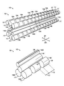
of the bearings
116A-B are vertically adjusted toward the respective work rolls 104A-B to
increase the bearing
load and therefore to increase the work roll pressure on the metal substrate
108 at localized areas
(i.e., the localized pressure at a particular area or areas is increased). The
bearings 116A-B or a
subset of the bearings 116A-B may be adjusted such that the load on each
bearing 116A-B is
from about 2 kgf to about 20,000 kgf As one non-limiting example, the load on
each bearing
116A-B may be from about 300 kgf to about 660 kgf. In some examples, the
bearings 116A-B,
or a subset of the bearings 116A-B, are adjusted such that the work roll
pressure at one or more
localized areas is about 610 kgf. In various examples, the load on each
bearing 116A-B may
depend on the dimensions of the bearing, a hardness of the substrate 108,
and/or the desired
texture.
[00571 As noted above, each of the bearings 116A-B may be individually
adjusted, or sets of the
bearings 116A-B may be adjusted together. For example, in some cases,
vertically adjusting the
bearings 116A-B includes vertically adjusting all of the bearings 116A-B. In
other examples,
each bearing 116A-B is individually adjusted. For example, in some cases, the
edge bearing 117
is vertically adjusted relative to the edges of the metal substrate 108 to
adjust the localized
pressure at the edge portions of the metal substrate 108. The vertical
adjustment of the edge
bearings 117 may be different from the vertical adjustment of the other
bearings 116A-B that
indirectly apply a load to the non-edge portions of the metal substrate 108.
Vertically adjusting
the edge bearings 117 may include vertically moving the edge bearings 117
toward the work
rolls 104A-B to increase the localized pressure at the edge portions of the
metal substrate 108.
18
CA 03069978 2020-01-14
WO 2019/018740 PCT/US2018/043047
Vertically adjusting the edge bearings 117 may also include vertically moving
the edge bearings
117 away from the work rolls 104A-B to decrease the localized pressure at the
edge portions of
the metal substrate 108.
[0058] The edge bearing 117 lateral position relative to an edge of the metal
substrate 108 also
may be adjusted through the controller or an operator. It was surprisingly
found that by
controlling a position of the edge-portion of the metal substrate 108 relative
to the first edge 118
and the second edge 120 of the edge bearing 117, the edge effects could be
controlled. In some
examples, the edge bearings 117 are laterally adjusted such that the edge of
the metal substrate
108 is between the first edge 118 and an intermediate position between the
first edge 118 and the
second edge 120. In other examples, the edge bearing 117 is laterally adjusted
such that the edge
of the metal substrate 108 is between the second edge 120 and the intermediate
position between
the first edge 118 and the second end 120. In various examples, the edge
bearing 117 is laterally
adjusted such that the edge of the metal substrate 108 is laterally outward
from the second edge
120 (i.e., at least some of the metal substrate 108 extends beyond the edge
bearing 117).
[0059] By adjusting one or more of the above pressure parameters of the mill
100, a desired
contact pressure distribution of the work rolls 104A-B on the metal substrate
108 can be
provided to result in a metal substrate 108 with improved texture consistency,
or a more uniform
texture over the surface and across the width of the metal substrate 108. In
some examples, the
pressure parameters are adjusted and controlled such that a thickness of the
metal substrate 108
remains substantially constant. In various examples, one or more pressure
parameters are
controlled to provide a desired contact pressure distribution that both
minimizes pressure
variation and reduces edge effects of the metal substrate 108 that occur
during texturing.
[00601 In some examples, the control system 122 includes a controller (not
shown), which may
be any suitable processing device, and one or more sensors 124. The number and
location of the
sensors 124 shown in FIG. 1 is for illustration purposes only and can vary as
desired. The
sensors 124 are configured to monitor the rolling mill 100 and/or stand
processing conditions.
For example, in some cases, the sensors 124 monitor the contact pressure
distribution of the
work rolls 104A-B on the metal substrate 108. Depending on the sensed contact
pressure
distribution, one or more pressure parameters are adjusted (through the
controller and/or the mill
operator or otherwise) to provide the desired contact pressure distribution.
In some examples, the
one or more pressure parameters are adjusted such that pressure variation and
edge effects are
19
CA 03069978 2020-01-14
WO 2019/018740 PCT/US2018/043047
minimized without changing the thickness of the metal substrate 108. In some
examples, the one
or more pressure parameters are adjusted such that a more uniform texture of
the metal substrate
108 is achieved.
[0061] In various examples, a method of applying a texture to the metal
substrate 108 includes
passing the metal substrate 108 through the gap 106. As the metal substrate
108 passes through
the gap 106, the work rolls 104A-B apply work roll pressure to the upper
surface 110 and the
lower surface 112 of the metal substrate 108 across the width of the metal
substrate 108 such that
the texture of the one or more work rolls 104A-B is transferred to the metal
substrate 108 while
the thickness of the metal substrate remains substantially constant In some
examples, the
method includes measuring the contact pressure distribution across the width
of the metal
substrate 108 with at least one of the sensors 124 and receiving data from the
sensor at the
processing device of the control system 122. In various examples, the method
includes
maintaining or adjusting at least one pressure parameter of the mill 100 such
that the work roll
pressure applied by the work rolls 104A-B across the width of the metal
substrate 108 provides
the desired contact pressure distribution across the width of the metal
substrate 108 and the
thickness of the metal substrate 108 remains substantially constant
[0062] In some examples, at least one of the pressure parameters is adjusted
to provide a
pressure variation of the contact pressure distribution over the surface and
across the width of the
metal substrate 108 that is less than a certain percentage. For example, in
some cases, at least one
of the pressure parameters is adjusted such that the pressure variation of the
contact pressure
distribution across the width of the metal substrate 108 is less than about
25%. In other cases, at
least one of the pressure parameters is adjusted such that the pressure
variation of the contact
pressure distribution across the width of the metal substrate 108 is less than
about 13%. In
further examples, at least one of the pressure parameters is adjusted such
that the pressure
variation of the contact pressure distribution across the width of the metal
substrate 108 is less
than about 8%. By reducing the variation of the contact pressure distribution
across the width of
the metal substrate 108, the texture transferred to the metal substrate 108 is
more uniform with
respect to at least one texture characteristic compared to textures applied
under contact pressure
distributions having greater variation.
[0063] One or more pressure parameters described above may be adjusted to
provide the desired
contact pressure distribution that both minimizes pressure variation and
reduces edge effects of
CA 03069978 2020-01-14
WO 2019/018740 PCT/US2018/043047
the metal substrate 108 from processing to provide a more uniform texture
along the metal
substrate 108 while an overall thickness of the metal substrate 108 remains
substantially
constant. As one non-limiting example, to provide the desired contact pressure
distribution, the
method may include at least one of increasing the work roll diameter and/or
the intermediate roll
diameter, reducing the bearing spacing 121 to the minimum bearing spacing 121,
and positioning
the edge bearings 117 such that the edge of the metal substrate 108 extends
beyond the second
edge 120 of the edge bearing 117. As another non-limiting example, to provide
the desired
contact pressure distribution, the applied load profile (i.e., the
distribution of load over the
bearings along the width of the roll configuration) is adjusted to obtain a
desired work roll
pressure and texture across the width of the substrate 108.
[0064] FIGS. 4-6 illustrate examples of the effect of adjusting two exemplary
pressure
parameters (roll diameter and position of the edge bearing 117 relative to the
edge of the metal
substrate 108) on contact pressure distribution. In each of FIGS. 4-6, line
402 represents the
pressure distribution of a metal substrate where the edge of the metal
substrate 108 is between
the first edge 118 and an intermediate position between the first edge 118 and
the second edge
120. Line 404 in each of FIGS. 4-6 represents the pressure distribution of a
metal substrate where
the edge of the metal substrate 108 is between the second edge 120 and the
intermediate position
between the first edge 1 I 8 and the second edge 120. Line 404 in each of
FIGS. 4-6 represents the
pressure distribution of a metal substrate where the edge of the metal
substrate 108 extends
outward from the second edge 120.
[0065] For the line 402 in all of FIGS. 4-6, eight bearings are illustrated.
For bearings 1-6, the
localized pressure applied by each bearing was 610 kgf. For bearing 7, the
localized pressure
applied was 610/4 kgf. Bearing 8 was fixed in they direction, meaning that no
localized pressure
was applied.
[0066] For the line 404, in all of FIGS. 4-6, eight bearings are illustrated.
For bearings 1-6, the
localized pressure applied by each bearing was 610 kgf. For bearing 7, the
localized pressure
applied was 610/2 kgf. Bearing 8 was fixed in the y direction, meaning that no
localized pressure
was applied.
[00671 For line 406, in all of FIGS. 4-6, eight bearings are illustrated. For
bearings 1-7, the
localized pressure applied by each bearing was 610 kgf. Bearing 8 was fixed in
the y direction,
meaning that no localized pressure was applied.
21
CA 03069978 2020-01-14
WO 2019/018740 PCT/US2018/043047
[0068] In FIG. 4, the diameters of the work rolls applying the work roll
pressure to each of the
metal substrates are the same. In FIG. 5, the work roll diameters are
increased by a factor of 1.5
relative to the work roll diameters of FIG. 4. In FIG. 6, the work roll
diameters are increased by a
factor of 2 relative to the work roll diameters of FIG. 4.
[0069] In general, for any of lines 402, 404, or 406, FIG. 4 illustrates
increased variation in the
contact pressure distribution as well as increased edge effects (e.g.,
represented by the pressure
variation starting at bearing 7). For any of lines 402, 404, or 406, FIG. 6
illustrates the best
control of pressure variation (i.e., the variation of the contact pressure
distribution is minimized),
but the edge effects are increased. Of the FIGS. 4-6, for any of lines 402,
404, or 406, FIG. 5
illustrates the best combination of minimized pressure variation while
reducing edge effects in
the contact pressure distribution.
[0070] Therefore, the disclosed system can be used to achieve a more uniform
texture on a metal
substrate by adjusting the one or more pressure parameters to produce a
contact pressure
distribution that minimizes pressure variation while reducing edge effects. By
optimizing the
pressure parameters to produce the desired contact pressure distribution,
metal substrates with
improved texture uniformity may be produced.
[0071] In some examples, one side of the work stand may be frozen such that
only one side of
the stand is actuated (i.e., the stand is actuated only in the direction 103
or only in the direction
105). In such examples, the vertical position of the lower work roll 104B is
constant, fixed,
and/or does not move vertically against the metal substrate.
[0072] In some aspects where bearings are included on both the upper and lower
sides of the
stand, one side of the work stand may be frozen by controlling one set of
bearings such that they
are not actuated. For example, in some cases, the lower bearings 116B may be
frozen such that
the lower work roll 104B not actuated in the direction 105. In other examples,
the lower bearings
116B may be omitted such that the lower work roll 104B is frozen. In other
examples, various
other mechanisms may be utilized such that one side of the stand is frozen.
For example, FIGs. 7
and 8 illustrate an additional example of a work stand where one side is
frozen, and FIGS. 9 and
illustrate a further example of a work stand where one side is frozen. Various
other suitable
mechanisms and/or roll configurations for freezing one side of the work stand
while providing
the necessary support to the frozen side of the work stand may be utilized.
22
[0073] FIGs. 7 and 8 illustrate another example of a work stand 702. The work
stand 702 is
substantially similar to the work stand 102 except that the work stand 702
includes fixed backup
rolls 725 in place of the lower bearings 116B. In this example, the fixed
backup rolls 725 are not
vertically actuated, and as such the work stand 702 is only actuated in the
direction 103.
Optionally, the backup rolls 725 are supported on a stand 723 or other
suitable support as
desired. Optionally, the stand 723 supports each backup roll 725 at one or
more locations along
the backup roll 725. In the example of FIGs. 7 and 8, three backup rolls
725are provided;
however, in other examples, any desired number of backup rolls 725 may be
provided. In these
examples, because the backup rolls 725 are vertically fixed, the lower work
roll 104B is frozen,
meaning that the lower work roll 104b is constant, fixed, and/or does not move
vertically against
the metal substrate. In such examples, the actuation in the stand 702 during
texturing is only
from one side of the stand 702 (i.e., actuation is only from the upper side of
the stand with the
upper work roll 104A).
[0074] FIGs. 9 and 10 illustrate another example of a work stand 902. The work
stand 902 is
substantially similar to the work stand 102 except that the intermediate rolls
and actuators are
omitted, and a diameter of the lower work roll 104B is greater than the
diameter of the upper
work roll 104A. In this example, the work stand 902 is only actuated in the
direction 103. In
some aspects, the larger diameter lower work roll I 04B provides the needed
support against the
actuation such that the desired profile of the metal substrate 108 is created
during texturing. It
will be appreciated that in other examples, intermediate rolls and/or various
other support rolls
may be provided with the lower work roll 104B. In further examples, the lower
work roll 104B
may have a similar diameter as the upper work roll 104A and the work stand
further includes any
desired number of intermediate rolls and/or support rolls to provide the
necessary support to the
lower work roll 104B when one side is frozen.
[0075] A collection of exemplary embodiments, including at least some
explicitly enumerated as
"ECs" (Example Combinations), providing additional description of a variety of
embodiment
types in accordance with the concepts described herein are provided below.
These examples are
not meant to be mutually exclusive, exhaustive, or restrictive; and the
invention is not limited to
these example embodiments but rather encompasses all possible modifications
and variations
within the scope of the issued claims and their equivalents.
23
Date Recue/Date Received 2022-05-06
CA 03069978 2020-01-14
WO 2019/018740 PCT/US2018/043047
[0076] EC 1. A method of applying a texture on a substrate, the method
comprising: applying a
texture to a substrate with a work stand of a coil-to-coil process, wherein
the work stand
comprises an upper work roll and a lower work roll vertically aligned with the
upper work roll,
wherein at least one of the upper work roll and the lower work roll comprises
the texture, and
wherein applying the texture comprises: applying, by the upper work roll, a
first work roll
pressure on an upper surface of the substrate; and applying, by the lower work
roll, a second
work roll pressure on a lower surface of the substrate; measuring a contact
pressure distribution
of at least one of the first work roll pressure and the second work roll
pressure across a width of
the substrate with a sensor; receiving data at a processing device from the
sensor; and adjusting a
contact pressure parameter of the work stand such that the work stand provides
a desired contact
pressure distribution across the width of the substrate and a thickness of the
substrate remains
substantially constant after the texture has been applied.
[0077] EC 2. The method of any of the preceding or subsequent examples,
wherein adjusting the
contact pressure parameter adjusts at least one characteristic of the texture
on the substrate.
[0078] EC 3. The method of any of the preceding or subsequent examples,
wherein the at least
one characteristic comprises a height of the texture, a depth of the texture,
a shape of the texture,
a size of the texture, a distribution of the texture, a coarseness of the
texture, or a concentration
of the texture.
[0079] EC 4. The method of any of the preceding or subsequent examples,
wherein adjusting the
contact pressure parameter comprises providing the desired contact pressure
distribution having
a contact pressure variation across the width of the substrate of less than
25%.
[00801 EC 5. The method of any of the preceding or subsequent examples,
wherein the contact
pressure variation across the width of the substrate is less than 13%.
[00811 EC 6. The method of any of the preceding or subsequent examples,
wherein the contact
pressure variation across the width of the substrate is less than 8%.
[00821 EC 7. The method of any of the preceding or subsequent examples,
wherein adjusting the
contact pressure parameter comprises adjusting a cylindricity of the work
rolls such that a
variation of cylindricity is less than 10 pm.
(00831 EC 8. The method of any of the preceding or subsequent examples,
wherein the work
stand further comprises an upper intermediate roll supporting the upper work
roll and a lower
intermediate roll supporting the lower work roll.
24
CA 03069978 2020-01-14
WO 2019/018740 PCT/US2018/043047
[0084] EC 9. The method of any of the preceding or subsequent examples,
wherein adjusting the
contact pressure parameter comprises adjusting a cylindricity of the
intermediate rolls such that a
variation of cylindricity is less than 10 gm.
[0085] EC 10. The method of any of the preceding or subsequent examples,
wherein the work
rolls have a work roll diameter and the intermediate rolls have an
intermediate roll diameter, and
wherein adjusting the contact pressure parameter comprises adjusting at least
one of the work
roll diameter and the intermediate roll diameter.
100861 EC 11. The method of any of the preceding or subsequent examples,
wherein the work
roll diameter is from about 20 mm to about 200 mm, and wherein the
intermediate roll diameter
is from about 20 mm to about 300 mm.
[0087] EC 12. The method of any of the preceding or subsequent examples,
wherein adjusting
the contact pressure parameter comprises increasing at least one of the work
roll diameter and
the intermediate roll diameter by a factor of 1.5.
[0088] EC 13. The method of any of the preceding or subsequent examples,
wherein adjusting
the contact pressure parameter comprises increasing at least one of the work
roll diameter and
the intermediate roll diameter by a factor of 2.
[0089] EC 14. The method of any of the preceding or subsequent examples,
wherein the upper
intermediate roll is a first upper intermediate roll, wherein the lower
intermediate roll is a first
lower intermediate roll, and wherein the work stand further comprises: a
second upper
intermediate roll supporting the upper work roll; and a second lower
intermediate role supporting
the lower work roll.
[00901 EC 15. The method of any of the preceding or subsequent examples,
wherein the work
stand further comprises: a set of upper bearings along the upper intermediate
roll, each upper
bearing applying a bearing load to the upper intermediate roll such that the
upper intermediate
roll causes the upper work roll to apply the first work roll pressure on the
substrate; and a set of
lower bearings along the lower intermediate roll, each lower bearing applying
a bearing load to
the lower intermediate roll such that the lower intermediate roll causes the
lower work roll to
apply the second work roll pressure on the substrate.
[0091] EC 16. The method of any of the preceding or subsequent examples,
wherein the set of
upper bearings comprises at least two rows of upper bearings, and wherein the
set of lower
bearings comprises at least two rows of lower bearings.
CA 03069978 2020-01-14
WO 2019/018740 PCT/US2018/043047
[0092] EC 17. The method of any of the preceding or subsequent examples,
wherein adjusting
the contact pressure parameter comprises adjusting a spacing between adjacent
upper bearings.
1.0093] EC 18. The method of any of the preceding or subsequent examples,
wherein adjusting
the spacing comprises decreasing the spacing between adjacent upper bearings
by changing a
lateral position of at least one of the upper bearings relative to an adjacent
upper bearing.
[0094] EC 19. The method of any of the preceding or subsequent examples,
wherein decreasing
the spacing comprises decreasing the spacing to a minimum spacing of about 1
mm.
100951 EC 20. The method of any of the preceding or subsequent examples,
wherein decreasing
the spacing comprises increasing a number of upper bearings along the upper
intermediate roll.
[00961 EC 21. The method of any of the preceding or subsequent examples,
wherein adjusting
the contact pressure parameter comprises adjusting a bearing dimension of at
least one upper
bearing of the set of upper bearings.
[0097] EC 22. The method of any of the preceding or subsequent examples,
wherein adjusting
the bearing dimension comprises changing at least one of a bearing width or a
bearing diameter.
[0098] EC 23. The method of any of the preceding or subsequent examples,
wherein the bearing
width is from about 20 mm to about 400 mm, and wherein the bearing diameter is
from about 20
mm to about 400 mm.
[0099] EC 24. The method of any of the preceding or subsequent examples,
wherein the bearing
width is about 100 mm.
[0100] EC 25. The method of any of the preceding or subsequent examples,
wherein adjusting
the bearing dimension comprises increasing a bearing width while maintaining
lateral positions
of the upper bearings, wherein increasing the bearing width decreases a
spacing between
adjacent upper bearings.
[0101] EC 26. The method of any of the preceding or subsequent examples,
wherein increasing
the bearing width comprises reducing a number of upper bearings along the
upper intermediate
roll.
[0102] EC 27. The method of any of the preceding or subsequent examples,
wherein adjusting
the contact pressure parameter comprises reducing a crown or chamfer height of
each one of the
upper bearings or lower bearings to be less than about 50 pm.
26
CA 03069978 2020-01-14
WO 2019/018740 PCT/US2018/043047
[0103] EC 28. The method of any of the preceding or subsequent examples,
wherein adjusting
the contact pressure parameter comprises decreasing the crown or chamfer
height of each one of
the upper bearings or lower bearings to about 20 Ltrn.
[0104] EC 29. The method of any of the preceding or subsequent examples,
wherein each one of
the upper bearings is individually adjustable relative to the upper
intermediate roll, and wherein
adjusting the contact pressure parameter comprises increasing the bearing load
applied by at least
one of the upper bearings on the upper intermediate roll.
101051 EC 30. The method of any of the preceding or subsequent examples,
wherein adjusting
the contact pressure parameter comprises increasing the bearing load applied
by all of the upper
bearings on the upper intermediate roll.
[0106] EC 31. The method of any of the preceding or subsequent examples,
wherein the set of
upper bearings comprises an outermost upper bearing having an inner end and an
outer end, and
wherein adjusting the contact pressure parameter comprises adjusting the
outermost upper
bearing relative to an edge of the substrate.
[0107] EC 32. The method of any of the preceding or subsequent examples,
wherein adjusting
the outermost upper bearing comprises moving the outermost upper bearing such
that the edge of
the substrate is between the inner end and an intermediate position of the
outermost upper
bearing, wherein the intermediate position is between the outer end and the
inner end.
[0108] EC 33. The method of any of the preceding or subsequent examples,
wherein adjusting
the outermost upper bearing comprises moving the outermost upper bearing such
that the edge of
the substrate is between the outer end and an intermediate position of the
outermost upper
bearing, wherein the intermediate position is between the outer end and the
inner end.
[0109] EC 34. The method of any of the preceding or subsequent examples,
wherein adjusting
the outermost upper bearing comprises moving the outermost upper bearing such
that the edge of
the substrate extends axially outward from the outer end of the outermost
upper bearing.
[0110] EC 35. The method of any of the preceding or subsequent examples,
wherein adjusting
the outermost upper bearing comprises increasing the bearing load applied by
the outermost
upper bearing to the upper intermediate roll to cause the upper work roll to
increase the work roll
pressure at the edge of the substrate.
27
CA 03069978 2020-01-14
WO 2019/018740 PCT/US2018/043047
110111] EC 36. The method of any of the preceding or subsequent examples,
wherein the first
work roll pressure and the second work roll pressure are from about 1 MPa to
about a yield
strength of the substrate.
[0112] EC 37. The method of any of the preceding or subsequent examples,
wherein a variation
in thickness across the width of the substrate is less than 2% after the
texture has been applied.
[0113] EC 38. The method of any of the preceding or subsequent examples,
wherein the work
stand is a first work stand, the upper work roll is a first upper work roll,
the texture is a first
texture, and the lower work roll is a first lower work roll, and wherein the
method further
comprises: applying a second texture to a substrate with a second work stand
of the coil-to-coil
process, wherein the second work stand comprises a second upper work roll and
a second lower
work roll vertically aligned with the second upper work roll, wherein at least
one of the second
upper work roll and the second lower work roll comprises the second texture,
and wherein
applying the second texture comprises: applying, by the second upper work
roll, a third work roll
pressure on the upper surface of the substrate; and applying, by the second
lower work roll, a
fourth work roll pressure on a lower surface of the substrate, wherein the
thickness of the
substrate remains substantially constant after the second texture has been
applied.
[0114] EC 39. The method of any of the preceding or subsequent examples,
wherein the first
work roll pressure and the second work roll pressure are less than a yield
strength of the
substrate.
[0115] EC 40. The substrate formed from the method of any of the preceding or
subsequent
examples.
[01161 EC 41. The method of any of the preceding or subsequent examples,
wherein the
thickness of the substrate decreases by no more than 1% after the texture has
been applied.
[0117] EC 42. The method of any of the preceding or subsequent examples,
wherein the
thickness of the substrate decreases by no more than 0.5% after the texture
has been applied.
[0118] EC 43. The method of any of the preceding or subsequent examples,
wherein the first
work roll pressure and the second work roll pressure are substantially the
same.
[0119] EC 44. A coil-to-coil processing system comprising: a work stand
comprising: an upper
work roll configured to apply a first work roll pressure on an upper surface
of a substrate; and a
lower work roll vertically aligned with the upper work roll and configured to
apply a second
work roll pressure on a lower surface of the substrate, wherein at least one
of the upper work roll
28
CA 03069978 2020-01-14
WO 2019/018740 PCT/US2018/043047
and the lower work roll comprises a texture such that at least one of the
upper work roll and the
lower work roll are configured to impart the texture on the substrate by
applying the first work
roll pressure or applying the second work roll pressure; and a sensor
configured to measure a
contact pressure distribution of at least one of the first work roll pressure
and the second work
roll pressure across a width of the substrate; a processing device configured
to receive data from
the sensor; and a contact pressure parameter, wherein the contact pressure
parameter is
adjustable based on the measured contact pressure distribution to achieve a
desired contact
pressure distribution across the width of the substrate and a thickness of the
substrate remains
substantially constant after the texture has been applied.
[0120] EC 45. The coil-to-coil processing system of any of the preceding or
subsequent
examples, wherein the contact pressure parameter comprises a cylindricity of
the work rolls, and
wherein the work rolls comprise a variation in cylindricity of less than about
10 um along a
width of the work rolls.
[0121] EC 46. The coil-to-coil processing system of any of the preceding or
subsequent
examples, wherein the work stand further comprises an upper intermediate roll
supporting the
upper work roll and a lower intermediate roll supporting the lower work roll.
[0122] EC 47. The coil-to-coil processing system of any of the preceding or
subsequent
examples, wherein the contact pressure parameter comprises a cylindricity of
the intermediate
rolls, and wherein the intermediate rolls comprise a variation in cylindricity
of less than about 10
um along a width of the intermediate rolls.
[0123] EC 48. The coil-to-coil processing system of any of the preceding or
subsequent
examples, wherein the work rolls have a work roll diameter and the
intermediate rolls have an
intermediate roll diameter, and wherein the contact pressure parameter
comprises at least one of
the work roll diameter and the intermediate roll diameter.
[0124] EC 49. The coil-to-coil processing system of any of the preceding or
subsequent
examples, wherein the work roll diameter is from about 20 mm to about 200 mm,
and wherein
the intermediate roll diameter is from about 20 mm to about 300 mm.
[0125] EC 50. The coil-to-coil processing system of any of the preceding or
subsequent
examples, wherein the upper intermediate roll is a first upper intermediate
roll, wherein the lower
intermediate roll is a first lower intermediate roll, wherein the work stand
further comprises: a
29
CA 03069978 2020-01-14
WO 2019/018740 PCT/US2018/043047
second upper intermediate roll supporting the upper work roll; and a second
lower intermediate
role supporting the lower work roll.
1.0126] EC 51. The coil-to-coil processing system of any of the preceding or
subsequent
examples, wherein the work stand further comprises: a set of upper bearings
along the upper
intermediate roll, each upper bearing configured to apply a bearing load to
the upper
intermediate roll such that the upper intermediate roll causes the upper work
roll to apply the first
work roll pressure on the substrate; and a set of lower bearings along the
lower intermediate roll,
each lower bearing configured to apply a bearing load to the lower
intermediate roll such that the
lower intermediate roll causes the lower work roll to apply the second work
roll pressure on the
substrate.
[0127] EC 52. The coil-to-coil processing system of any of the preceding or
subsequent
examples, wherein the set of upper bearings comprises at least two rows of
upper bearings, and
wherein the set of lower bearings comprises at least two rows of lower
bearings.
[0128] EC 53. The coil-to-coil processing system of any of the preceding or
subsequent
examples, wherein the contact pressure parameter comprises a spacing between
adjacent upper
bearings.
[0129] EC 54. The coil-to-coil processing system of any of the preceding or
subsequent
examples, wherein the spacing is about 34 mm.
[0130] EC 55. The coil-to-coil processing system of any of the preceding or
subsequent
examples, wherein the contact pressure parameter comprises a bearing dimension
of at least one
upper bearing of the set of upper bearings.
[01311 EC 56. The coil-to-coil processing system of any of the preceding or
subsequent
examples, wherein the bearing dimension comprises a bearing diameter and a
bearing width.
[0132] EC 57. The coil-to-coil processing system of any of the preceding or
subsequent
examples, wherein the bearing diameter is from about 20 mm to about 400 mm,
and wherein the
bearing width is from about 20 mm to about 400 mm.
[0133] EC 58. The coil-to-coil processing system of claim 56, wherein the
bearing width is about
100 mm.
[0134] EC 59. The coil-to-coil processing system of any of the preceding or
subsequent
examples, wherein the contact pressure parameter comprises a crown or chamfer
height of each
one of the upper bearings or the lower bearings to be less than about 50 gm.
CA 03069978 2020-01-14
WO 2019/018740 PCT/US2018/043047
[0135] EC 60. The coil-to-coil processing system of any of the preceding or
subsequent
examples, wherein the crown of each one of the upper bearings or the lower
bearings is about 20
Inn
[0136] EC 61. The coil-to-coil processing system of any of the preceding or
subsequent
examples, wherein each one of the upper bearings is individually adjustable
relative to the upper
intermediate roll, and wherein the contact pressure parameter comprises the
bearing load applied
by at least one of the upper bearings on the upper intermediate roll.
101371 EC 62. The coil-to-coil processing system of any of the preceding or
subsequent
examples, wherein the contact pressure parameter comprises the bearing load
applied by all of
the upper bearings on the upper intermediate roll.
[0138] EC 63. The coil-to-coil processing system of any of the preceding or
subsequent
examples, wherein the set of upper bearings comprises an outermost upper
bearing having an
inner end and an outer end, and wherein the contact pressure parameter
comprises a position of
the outermost upper bearing relative to an edge of the substrate.
[0139] EC 64. The coil-to-coil processing system of any of the preceding or
subsequent
examples, wherein the outermost upper bearing is positioned such that the edge
of the substrate
is between the inner end and an intermediate position of the outermost upper
bearing, wherein
the intermediate position is between the outer end and the inner end.
[0140] EC 65. The coil-to-coil processing system of any of the preceding or
subsequent
examples, wherein the outermost upper bearing is positioned such that the edge
of the substrate
is between the outer end and an intermediate position of the outermost upper
bearing, wherein
the intermediate position is between the outer end and the inner end.
[0141] EC 66. The coil-to-coil processing system of any of the preceding or
subsequent
examples, wherein the outermost upper bearing is positioned such that the edge
of the substrate
extends axially outward from the outer end of the outermost upper bearing.
[0142] EC 67. The coil-to-coil processing system of any of the preceding or
subsequent
examples, wherein a variation in thickness across the width of the substrate
is less than 2% after
the texture is applied.
[0143] EC 68. The coil-to-coil processing system of any of the preceding or
subsequent
examples, wherein the first work roll pressure and the second work roll
pressure are less than a
yield strength of the substrate.
31
CA 03069978 2020-01-14
WO 2019/018740 PCT/US2018/043047
[0144] EC 69. The method of any of the preceding or subsequent examples,
wherein adjusting
the contact pressure parameter comprises adjusting the bearing loads applied
by the upper
bearings on the upper intermediate roll to adjust a distribution of the
bearing loads.
[0145] EC 70. The system or method of any of the preceding or subsequent
example
combinations, wherein the upper work roll is vertically adjustable and wherein
the lower work
roll is vertically fixed such that only the upper work roll is actuatable.
[0146] The above-described aspects are merely possible examples of
implementations, merely
set forth for a clear understanding of the principles of the present
disclosure. Many variations and
modifications can be made to the above-described example(s) without departing
substantially
from the spirit and principles of the present disclosure. All such
modifications and variations are
included herein within the scope of the present disclosure, and all possible
claims to individual
aspects or combinations of elements or steps are intended to be supported by
the present
disclosure. Moreover, although specific terms are employed herein, as well as
in the claims that
follow, they are used only in a generic and descriptive sense, and not for the
purposes of limiting
the described invention, nor the claims that follow.
32