Note: Descriptions are shown in the official language in which they were submitted.
CA 03070086 2020-01-16
WO 2019/014721
PCT/AU2018/050757
METHOD AND SYSTEM FOR DISTRIBUTED ACOUSTIC SENSING IN A
MARINE ENVIRONMENT
Field of the invention
The present invention generally relates to a method and system of distributed
acoustic sensing in a marine environment.
Background of the invention
Marine environments requiring ISR (intelligence, surveillance and
reconnaissance) often cover vast areas, making effective monitoring of these
areas
logistically difficult and expensive. Existing ISR methods for these areas
generally
include monitoring by satellites, sonar units mounted to the underside of a
marine
vessel or a sonar array towed behind a marine vessel.
Fibre-optic distributed acoustic sensing can detect acoustic events in
surrounding regions along an optical fibre, whereby different types of
incidents may
cause different acoustic signatures in the acoustic event. In a marine
environment, an
acoustic event can be caused by incidents such as a marine vessel travelling
through
the area.
Some fibre-optic distributed acoustic sensing methods utilise a hydrophone
detector that uses an optical signal to sense the acoustic disturbance
occurring within
the marine environment. The hydrophone detector converts these to an electric
signal,
which is communicated to a recording station, before being recorded at a
recording
station. These methods may be used, for example, in systems for temporary
monitoring
of the marine environment. The hydrophone detectors used in these sensing
methods
usually do not have access to a permanent source of power or a permanent
mechanism
for communicating the recorded information.
Reference to any prior art in the specification is not an acknowledgment or
suggestion that this prior art forms part of the common general knowledge in
any
jurisdiction or that this prior art could reasonably be expected to be
understood,
1
CA 03070086 2020-01-16
WO 2019/014721
PCT/AU2018/050757
regarded as relevant, and/or combined with other pieces of prior art by a
skilled person
in the art.
Summary of the invention
Embodiments of a system for distributed acoustic sensing in a marine
environment surrounding a repeater along a fibre-optic submarine
communications
cable, comprise:
at least one distributed acoustic sensing (DAS) unit, each DAS unit
comprising:
a light source that is configured to transmit outgoing light in at least
one fibre-optic sensing cable located in the marine environment;
and
a receiver configured to receive reflected light of the outgoing light
that has been back scattered along the at least one fibre-optic
sensing cable, the reflected light including at least one optical
property influenced by an acoustic disturbance in the marine
environment; and
an optical multiplexer for multiplexing optical signals onto the fibre-optic
submarine communications cable via the repeater, the optical signals carrying
information on the at least influenced optical property.
In some embodiments, the optical multiplexer is configured to multiplex the
optical signals onto the fibre-optic submarine communications cable via a loop
back
coupler of the repeater.
In some embodiments, the optical multiplexer is configured to time-multiplex
and/or frequency-multiplex the optical signals with other optical signals
carried on the
fibre-optic submarine communications cable.
In some embodiments, the optical multiplexer includes an optical transmitter
configured to generate the optical signals based on the information on the at
least
influenced optical property.
2
CA 03070086 2020-01-16
WO 2019/014721
PCT/AU2018/050757
In some embodiments, the at least one DAS unit is powered by the repeater.
In some embodiments, the at least one fibre-optic sensing cable comprise at
least two fibre-optic sensing cables and wherein the at least one DAS unit
comprises
multiple spaced apart DAS units, wherein the DAS units are connected via a
distribution
hub which in turn communicates with the repeater via a power and data cable.
In some embodiments, the at least one of the fibre-optic sensing cables is
provided with a magneto-restrictive coating for distributed magnetic sensing
in the
marine environment surrounding the repeater.
In some embodiments, a combination of fibre-optic acoustic and fibre-optic
magneto-restrictive sensing cables provide both distributed acoustic and
distributed
magnetic sensing in the same marine environment.
Embodiments of a method for distributed acoustic sensing in a marine
environment surrounding a repeater along a fibre-optic submarine
communications
cable, comprise:
transmitting outgoing light from a light source of at least one distributed
acoustic
sensing (DAS) unit in at least one fibre-optic sensing cable located in the
marine
environment;
receiving reflected light of the outgoing light at a receiver of the at least
one DAS
unit, the reflected light being outgoing light that has been back scattered
along the at
least one fibre-optic sensing cable and includes at least one optical property
influenced
by an acoustic disturbance in the marine environment; and
multiplexing, via an optical multiplexer, optical signals onto the fibre-optic
submarine communications cable via the repeater, the optical signals carrying
information on the at least influenced optical property.
In some embodiments, the multiplexing of the optical signals onto the fibre-
optic
submarine communications cable is performed via a loop back coupler of the
repeater.
In some embodiments, the multiplexing occurs via time-multiplexing and/or
frequency multiplexing of the optical signals onto the fibre-optic submarine
communications cable.
3
CA 03070086 2020-01-16
WO 2019/014721
PCT/AU2018/050757
In some embodiments, the method further comprises generating, at an optical
transmitter of the optical multiplexer, the optical signals based on the
information on the
at least influenced optical property.
As used herein, except where the context requires otherwise, the term
"comprise" and variations of the term, such as "comprising", "comprises" and
"comprised", are not intended to exclude further additives, components,
integers or
steps.
Further aspects of the present invention and further embodiments of the
aspects
described in the preceding paragraphs will become apparent from the following
description, given by way of example and with reference to the accompanying
drawings.
Brief description of the drawings
Figure 1 is a diagram of a system for distributed acoustic sensing in a marine
environment;
Figure 2a is a front perspective view of a distributed acoustic sensing (DAS)
unit
used in the distributed acoustic sensing system of Figure 1;
Figure 2b is a diagram of the DAS unit shown in Figure 2a;
Figure 3a is a front view of a repeater for use with the DAS unit of Figures
2a-2b;
Figure 3b is a partial diagram of the repeater of Figure 3a connected to a
submarine communications cable; and
Figure 4 is a diagram of a loopback coupler module of the repeater shown in
Figures 3a-3b; and
Figure 5 is a density plot of electrical signals processed from the DAS unit
of
Figures 2a-2b.
Detailed description of the embodiments
Fibre-optic submarine communication cables are laid on the sea floor between
land-based communication stations and are used to transmit digital data, such
as
4
CA 03070086 2020-01-16
WO 2019/014721
PCT/AU2018/050757
telephone, Internet and private data, across spatially vast marine
environments.
Repeaters (e.g. two-way amplifiers) are placed at intervals along the fibre-
optic
submarine communication cable and are used to amplify the optical signal that
would
otherwise be attenuated during its transmission across the marine environment.
The
repeaters may be powered by electrical conductors located in the submarine
communication cables and are typically connected to a land-based power source.
The principle of fibre-optic distributed acoustic sensing relies on the
occurrence
of an acoustic event, from a stationary or moving object, causing a
corresponding
localised perturbation of the refractive index of an optical fibre. Due to the
perturbed
refractive index, an optical signal that is transmitted along the optical
fibre and then
back-scattered in a distributed manner (e.g. via Rayleigh scattering or other
similar
scattering phenomena) along the length of the fibre will include fluctuations
(e.g. in
intensity and/or phase) over time. The magnitude of the fluctuations relates
to the
severity or proximity of the acoustic event. The timing of the fluctuations
along the
distributed back-scattering time scale relates to the location of the acoustic
event.
The present disclosure includes a method and system for distributed acoustic
sensing, using in part a repeater located along a fibre-optic submarine
communications
cable. Utilizing the disclosed methods and systems, information related to a
detected
acoustic event is communicated onto the fibre-optic submarine communications
cable,
via the repeater. The information may be multiplexed with other signals
carried by the
fibre-optic submarine communications cable, for example using wavelength
division
multiplexing and/or time division multiplexing.
The disclosed system and method may be used with purposely deployed fibre-
optic submarine communication cables dedicated to distributed acoustic sensing
or, if
available, existing fibre-optic submarine communication cables, where one or
more of
the optical fibres are reserved for distributed acoustic sensing.
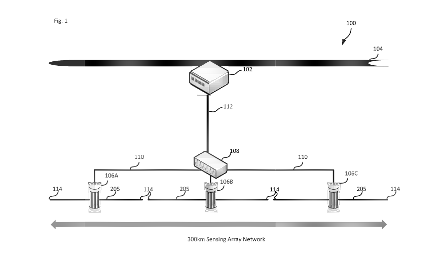
An example system 100 for distributed acoustic sensing in a marine
environment surrounding a repeater 102, at a location along a fibre-optic
submarine
communications cable 104, is shown in Figure 1. In general, the disclosed
system 100
includes at least one distributed acoustic sensing (DAS) unit 106, with Figure
1 showing
5
CA 03070086 2020-01-16
WO 2019/014721
PCT/AU2018/050757
three DAS units 106A, 106B and 106C. Each DAS unit 106 is communicatively
connected to at least one fibre-optic sensing cable 205. The at least one
fibre-optic
sensing cable 205 is also weighted or otherwise anchored at its free end 114
and at
appropriate intervals along the cable in order to anchor the fibre-optic
sensing cable to
the seafloor. In the example of Figure 1, each DAS unit 106 is communicatively
connected to two fibre-optic sensing cables 205 and positioned in a linear
configuration
with respect to one another. It will be appreciated that the DAS unit 106 can
be
positioned on the seafloor in any configuration, for example, a linear or non-
linear
configuration, which may be 2D or 3D, such as a serpentine or zig-zag
configuration.
In one embodiment, at least one fibre-optic sensing cable 205 may comprise a
magneto-restrictive coating for distributed magnetic sensing in the marine
environment
surrounding the repeater. The magneto-restrictive coated fibre-optic sensing
cable 205
may detect magnetic field perturbations created by a magnetic source, such as
a
marine vessel, travelling within the marine environment. The presence of the
magnetic
source, from a stationary or moving object, will cause a corresponding
localised
perturbation of the magnetic field surrounding the fibre-optic sensing cable
205 and in
turn the refractive index of the fibre-optic sensing cable 205. Due to the
perturbed
refractive index, an optical signal that is transmitted along the sensing
fibre-optic cable
205 is back-scattered in a distributed manner (e.g. via Rayleigh scattering or
other
similar scattering phenomena) along the length of the fibre and will include
fluctuations
(e.g. in intensity and/or phase) over time. The magnitude of the fluctuations
relates to
the severity or proximity of the magnetic source. The timing of the
fluctuations along the
distributed back-scattering time scale relates to the location of the magnetic
source.
In the embodiment shown in Figure 1, one fibre-optic sensing cable 205
extending from each DAS unit 106 may be provided with a magneto-restrictive
coating,
with the remaining fibre-optic sensing cable 205 is provided with a non-
magneto-
restrictive coating. This configuration of fibre-optic sensing cables 205 may
provide for
both distributed acoustic and distributed magnetic sensing in the same marine
environment.
In the embodiment shown in Figure 1, each DAS unit 106 is coupled to a
distribution hub 108 via a power and data cable 110. The distribution hub 108
is
6
CA 03070086 2020-01-16
WO 2019/014721
PCT/AU2018/050757
connected to the repeater 102 of the fibre-optic submarine cable 104, by a
power and
data cable 112. The distribution hub 108 may be spaced from the repeater 102
of the
fibre-optic submarine cable 104 at any suitable distance for power and data
communication purposes. In one example, the distribution hub 108 may be 10-50
km
from the repeater 102 of the fibre-optic submarine cable 104, with the power
and data
cables 110 and 112 being similarly anchored to the seafloor. More than one hub
108
may be provided for each repeater, allowing for an increased number of DAS
units 106
communicatively connected to the repeater where required. Other architectures
may be
used depending on requirements for the system, including a direct connection
between
the DAS 106 and the repeater 102, in which case the power and data cable 110
extends between the DAS unit 106 and the repeater 102, and including use of
other
network components, including routers and switches. In other embodiments power
and
data may be carried on separate cables between the DAS unit(s) 106, hub(s) 108
and
repeater 102. The network or communication line between the DAS unit(s) 106
and the
repeater may be in either the electrical or optical or acoustic domain.
In one embodiment, each DAS unit 106 transmits data signals, which carry
information relating to at least one optical property that has been influenced
by an
acoustic disturbance in the marine environment, via the data carrying
component of the
power and data cable 110, to the distribution hub 108. The distribution hub
108 passes
these data signals onto the repeater 102 via the data carrying component of
the power
and data cable 112. The repeater 102 transmits these data signals from the
repeater to
the fibre-optic submarine cable 104 via data cable 306 (Figure 3b). In some
embodiments the communication is unidirectional, from the DAS unit(s) 106 to
the
repeater 102. In other embodiments the communication is bidirectional allowing
for
example, control signals to be communicated from the repeater 102 to the DAS
unit(s)
106. The control signals may be received by the repeater 102 over the fibre-
optic
submarine cable 104.
In the embodiment shown in Figures 1 and 2b, a receiver 208 in the DAS unit
106 receives reflected optical light that has been back scattered along the at
least one
fibre-optic sensing cable 205, the reflected optical light including acoustic
information of
the least one optical property that has been influenced by an acoustic
disturbance in the
marine environment. The reflected optical light from each sensing fibre-optic
cable 205
7
CA 03070086 2020-01-16
WO 2019/014721
PCT/AU2018/050757
is digitised at a data rate of 3.2Gb/s and converted to an electrical signal.
A
demodulator in the DAS unit 106 demodulates the electrical signals to capture
the
acoustic information at a data rate of 200 Mb/s. A multiplexer located in each
DAS unit
106 then multiplexes the two 200 Mb/s electrical signals to a single 400 Mb/s
electrical
signal. The DAS unit then converts this electrical signal into an optical
signal and
transmits this along cable 110 to the distribution hub 108. The distribution
hub 108
optically multiplexes the three optical signals received from each of the DAS
units 106
and transmits this multiplexed optical signal to the repeater 102 of the
submarine
communications cable 104 via cable 112. The loop back coupler at the repeater
102
digitally time-multiplexes and/or frequency multiplexes the multiplexed
optical signal
with the optical signals travelling along the fibre optic pairs of the
submarine
communications cable 104.
The fibre-optic submarine cable 104 also includes a power cable 304 (Figure
3b) that supplies power to the repeater 102. Power is provided to the DAS
unit(s) 106
from the repeater 102, optionally via any distribution hub(s) 108 or other
intermediary
network components. These intermediary network components also source their
power
from the fibre-optic submarine cable 104, via the repeater 102.
In one example, the power and data cables 110, 112 may comprise six wire
connectors and a tether cable. Two of these wires may be a twisted pair cable
for power
distribution, for instance to the distribution hub 108 or the DAS unit 106,
and the
remaining four wires may be used for bidirectional data transmission between
the
distribution hub 108 or the DAS unit 106 and the repeater 102. The data
transmission
rates may be adjustable depending on the number of ports on the repeater 102.
For
example, a rate of 100 Mbs may be used between the distribution hub 108 or DAS
unit
106 and the repeater 102. In another example, a rate of 10 Gb/s may be used by
the
repeater 102 transmitting data to the distribution hub 108 or DAS unit 106.
In the embodiment shown in Figure 1, three DAS units 106A-106C are spaced
apart from each other, for example in the order of 100 km apart, with each DAS
unit
106A-C having two outwardly extending fibre-optic sensing cables, each having
a length
of about 50 km. The configuration shown in Figure 1 simulates a detector with
a
detection footprint having a diameter of about 300 km and spans a larger
submarine
8
CA 03070086 2020-01-16
WO 2019/014721
PCT/AU2018/050757
geographical area than would otherwise be spanned by any one of the DAS units
106
alone.
In some circumstances, different DAS units 106 may detect the same acoustic
event in the marine environment, with the detection used to increase the
spatial
accuracy of locating the acoustic event. For example, an acoustic event may be
detected by DAS units 106A, 106B but not by DAS unit 106C. Such detection may
indicate, for example, that the corresponding occurrence is located in the
marine
environment between DAS unit 106A and 106B. Timing data may be used to further
refine the determination of the position of the acoustic event, for example
using
triangulation.
An exemplary method for distributed acoustic sensing in a marine environment
surrounding a repeater along a fibre-optic submarine communications cable
includes
the steps of: (a) transmitting outgoing light from a light source of at least
one distributed
acoustic sensing (DAS) unit in at least one fibre-optic sensing cable located
in the
marine environment; (b) receiving reflected light of the outgoing light at a
receiver of the
at least one DAS unit, the reflected light being outgoing light that has been
back
scattered along the at least one fibre-optic sensing cable and includes at
least one
optical property influenced by an acoustic disturbance in the marine
environment; and
(c) multiplexing, via an optical multiplexer, optical signals onto the fibre-
optic submarine
communications cable via a repeater, the optical signals carrying information
on the at
least influenced optical property.
Distributed Acoustic Sensino (DAS) unit
One example of a distributed acoustic sensing (DAS) unit 106 that can be used
with a repeater 102 along a deployed or existing fibre-optic submarine
communications
cable 104, in order to detect acoustic disturbances within the marine
environment, is
shown in Figures 2a-2b.
The DAS unit 106 includes a pressurised housing 201 for withstanding the high
water pressures associated with various depths in the submarine environment,
for
example 0-7km. Within the pressurised housing 201, the DAS unit 106 includes a
coherent optical time-domain ref lectometer (OTDR) 202.
9
CA 03070086 2020-01-16
WO 2019/014721
PCT/AU2018/050757
The OTDR 202 includes a light source 204 to transmit outgoing light 206 in at
least one fibre-optic sensing cable 205, located in the marine environment and
extending outwardly from the DAS unit. The outgoing light 206 to be sent into
the optical
fibre 205 may be in the form of one or more short optical pulses. The light
source 204
may comprise one or a plurality of components, for example one or a plurality
of laser
devices.
The OTDR 202 includes a receiver 208, for example incorporating a
photodetector, which is configured to receive and detect reflected light 210
of the
outgoing light 206, comprising light that has been back scattered along the
fibre-optic
sensing cable 205. If the OTDR 202 is phase-sensitive, phase fluctuations in
the
reflected light may be additionally or alternatively measured. The reflected
light 210
includes at least one optical property that has been influenced by an acoustic
disturbance in the marine environment. As described above, the magnitude of
the
reflected light 210 may be indicative of the severity or proximity of the
acoustic
disturbance in the marine environment. In another example, the timing of
reflected light
210 may be indicative of the location of the acoustic event.
The reflected light 210 is considered an optical signal that carries
information
on the at least one optical property that has been influenced by the acoustic
disturbance. The DAS unit 106, for example by the OTDR 202, communicates a
first
signal based on this information to the optical multiplexer 214. The optical
multiplexer
214 multiplexes a second signal onto the fibre-optic submarine cable 104. The
optical
signals multiplexed onto the fibre-optic submarine communications cable 104
carrying
information on the at least one optical property influenced by the acoustic
disturbance.
As described above, the light source 204 and receiver 208 pair may be
provided in an optical time-domain reflectometer (OTDR) 202. The OTDR 202
includes
a transmitter 212 for transmitting data signals representative of the
reflected light 210
received by the OTDR 202.
The presently disclosed system and method of distributed acoustic sensing
may be used with phased array processing and beam forming techniques. As
mentioned above, outgoing light 106 may be sent into the fibre-optic sensing
cable 205
CA 03070086 2020-01-16
WO 2019/014721
PCT/AU2018/050757
as a series of optical pulses. The reflected light 210 produced as a result of
backscattering of the outgoing light 106 along the fibre-optic sensing cable
205 is
recorded against time at the receiver 208. This configuration permits
determination of
an acoustic signal (amplitude, frequency and phase) at every distance along
the fibre-
optic sensing cable 205. In one embodiment, the receiver 208 records the
arrival times
of the pulses of reflected light 210 in order to determine the location and
therefore the
channel where the reflected light was generated along the fibre-optic sensing
cable 205.
This phased array processing may permit improved signal-to-noise ratios in
order to
obtain improved long range detection of a marine acoustic source, as well as
the
direction, speed, location and classification of the acoustic source.
In order to determine the angle or the distance of the acoustic source from
the
fibre-optic sensing cable 205, beamforming techniques may be applied.
Beamforming
techniques involve the summation of an acoustic time series from adjacent
channels
along the fiber cable with varying degrees of time delay across each channel
(or spatial
position along the cable). The degree of time delay added to the acoustic
channels in
the summation processes alters the direction or location where the beam formed
by the
array processing becomes most sensitive. In one embodiment, beamforming is
performed in the time domain by sending the outgoing light 106 into the fibre-
optic
sensing cable 205 as a series of optical pulses. Each optical pulse produces a
measurement of the acoustic time series for each channel along the sensing
cable.
Beams are then formed mathematically from an evolving time series by varying
the time
delay of each channel going in to a summation. With no delay added across the
channels a beam is formed that is strongest at 90 degrees to the axis of the
fiber cable.
As incremental time delay is added across the channels, the main lobe of the
beam
moves spatially towards being most sensitive along the axis of the cable.
These
beamforming techniques may result in a narrow scanning beam that may yield
direction
of the marine acoustic source and its location relative to the fibre-optic
sensing cable
205 in order to selectively monitor different zones in the acoustic field with
improved
array gain range and enhanced detection capabilities.
Submarine Communications Cable and Repeater
11
CA 03070086 2020-01-16
WO 2019/014721
PCT/AU2018/050757
An embodiment of a modified repeater 102 is shown in Figures 3a-3b, which as
described above acts as an optical amplifier to the optical signals
transmitted along the
submarine communications cable 104. The repeater 102 comprises a port 302 for
coupling to the power and data cable 112. The repeater 102 transmits received
signals
relating to an acoustic disturbance from the DAS unit(s) 106 onto the fibre-
optic
submarine communications cable 104. The repeater 102 also transmits power to
the
DAS unit(s) 106.
In one embodiment, the optical multiplexer 214 is implemented in a loopback
coupler module 414 of the repeater 102 of the submarine communications cable
104,
for example as shown in Figure 4. The submarine communications cable 104
comprises
multiple optic-fibre pairs, where each optic-fibre pair provides a
bidirectional connection
with a symmetric data capacity between two land-based communication stations.
One
example of an optic-fibre pair comprising first and second optic-fibres 404a,
404b is
shown in Figure 4.
Couplers 406a, 406b are located along each of the first and second optic-
fibres
404a, 404b at the repeater 102 to couple the optical pump unit 412 to the
optical
amplifiers 408a, 408b. An optical light signal sent along the first and second
optic fibres
404a, 404b of the submarine communications cable 102 is amplified at the
amplifiers
408a, 408b. The resulting amplified optical signal is then transmitted a
further distance
along the submarine communications cable 102.
As shown in Figure 4, the repeater 102 further comprises a loopback coupler
module 414 that is coupled to the first and second optic fibres 404a, 404b,
respectively.
The loopback coupler module 414 may comprise Fibre Bragg Gratings (FBGs) 416a,
416b. Each FBG 416a, 416b may reflect a wavelength of optical light sent
within the first
or second optical fibres 404a or 404b of the submarine communications cable
104 back
in the direction of the land-based source station, while transmitting all
other wavelengths
along the remaining optical fibre 404a or 404b towards the land-based
destination
station. For example, a wavelength of optical light sent along optic-fibre
404b of the
submarine communications cable 102 may be reflected by the loopback coupler
module
414 and transmitted along optic-fibre 404a back in the direction of the land-
based
source station of optic-fibre 404b (corresponding to the direction of the land-
based
12
CA 03070086 2020-01-16
WO 2019/014721
PCT/AU2018/050757
destination station of optic-fibre 404a) as indicated by A in Figure 4, while
the remaining
wavelengths of light are transmitted along optic-fibre 404b towards the
destination land-
based station of optic-fibre 404b (corresponding to the direction of the land-
based
source station of optic-fibre 404a), as indicated by B in Figure 4.
As described herein above, in one embodiment, the loopback coupler module
414 is coupled directly to one or more DAS units 106. In another embodiment,
the
loopback coupler module 414 may be coupled to the DAS units 106 via one or
more
distribution hubs 108, and/or other network components.
The FBG's 416a, 416b of the loopback coupler module 414 may be used to
multiplex the reflected light from each DAS unit 106 into a combined optical
signal at a
particular wavelength. The resulting multiplexed optical signal includes at
least one
optical property that has been influenced by an acoustic disturbance in the
marine
environment, as detected by one or more DAS units 106. This multiplexed
optical signal
is then transmitted along optical fibre 404a or 404b. The optical signal may
be amplified
by one or more repeaters of the submarine communications cable. In one
example, the
multiplexed optical signal is transmitted along optical fibre 404a of the
submarine
communications cable 104 towards a destination land-based station of optic
fibre 404a.
In some embodiments, the multiplexed optical signal is a time-multiplexed
and/or
frequency multiplexed signal, with other optical signals that are transmitted
along the
fibre-optic submarine communications cable 104.
In some embodiments, the optical signals detected by the one or more DAS units
106 are passed directly onto the submarine communications cable 104. In other
embodiments the signals detected by the one or more DAS units 106 are
processed
and an output of the processing is communicated onto the submarine
communications
cable 104. For example, the optical transmitter may generate an optical signal
for
transmission along the submarine communications cable 104 only if the
fluctuations of
the reflected light received by each DAS unit 106 from the fibre-optic sensing
cable/s
105 are above a predetermined threshold value, indicating a relatively severe
acoustic
event or an acoustic event that has occurred close to the fibre-optic sensing
cables of
the relevant DAS unit(s) 106. The transmitted signal may be a simple flag
indicating
13
CA 03070086 2020-01-16
WO 2019/014721
PCT/AU2018/050757
occurrence of the event, or contain information about the event, for example a
location
determined by the processing of the signal or information to enable a location
determination or other analysis to be performed at a remote processor, for
example a
land-based processor.
Optical Sional Processina
As described above, the signals from the DAS units 106 may be processed, for
example to generate an alert signal representative of the detected acoustic
event.
Figure 5 illustrates an example density plot combining electrical signals 512
obtained
from the multiplexed optical signal. The horizontal axis (labelled "Channel")
represents
position along a sensing optical-fibre of a DAS unit 106, the vertical axis
(labelled
"Time") represents time, and the colour-coded amplitude of the plot represents
acoustic
intensity. In Figure 5, features such as straight lines with relatively
constant gradients
are associated with moving objects (with the gradients being indicative of
speed) that
cause the relevant acoustic event detected by the DAS unit 106. The acoustic
event
being determined may be indicative of specific stationary or moving
occurrences, such
as marine vessels, travelling through the marine environment surrounding the
DAS unit
106.
An alert may also be generated by classifying the alert signal into one or
more
classes of alerts (e.g. border intrusion etc.) based on acoustic signatures of
the
fluctuations of the optical signal received at the land-based station. Some
techniques in
alert classification are summarised and further referenced in, for example,
"Fiber
Sensing: Optical fiber monitors the arterial networks of commerce", Laser
Focus World,
volume-Si ,issue-08, 8 June 2015
(http://www.laserfocusworld.com/articles/print/volume-
51/issue-08/features/fiber-sensi ng-optical-fiber-monitors-the-arterial-
networks-of-
commerce.html). In one configuration, the marine environment to be sensed is
divided
into multiple zones corresponding to different sections along the fibre-optic
submarine
communications cable 104. In this configuration, each zone or corresponding
section is
associated with generation of one or more selected classes of alerts (or non-
generation
of one or more excluded classes of alerts). For example, the classes of alerts
selected
for generation may be associated with a vessel travelling through the marine
environment. In this example, the classes of alerts may increase in importance
as the
14
CA 03070086 2020-01-16
WO 2019/014721
PCT/AU2018/050757
marine vessel travels through the respective zones of the marine environment
and
towards a coastline. Additionally, the classes of alerts excluded for
generation may be
associated with wave motion, tectonic movement or undersea volcanic activity.
Acoustic calibration
A marine environment through which the distributed acoustic sensing is
conducted is likely an area with unwanted acoustic interference caused by wave
action,
biologics or the like. The unwanted acoustic interference may interfere, mask
or
otherwise affect the characteristics of the acoustic event being determined.
In one
configuration, to reduce the impact of unwanted acoustic interference,
spectral filtering
is applied to the detected fluctuations of the received optical light at the
land-based
station in order to reduce or remove fluctuations associated with the unwanted
acoustic
interference.
Further, spectral filtering may be selectively applied to one or more zones of
the marine environment. Different zones of the marine area may require
different or no
spectral filtering. For example, further away from the coastline there may be
less marine
vessel noise and there may be no need to apply filtering techniques.
Alternatively or
additionally, the disclosed method may selectively apply the spectral
filtering to
fluctuation based on time, e.g. the time of the day or the day of the week.
Spatial calibration
In one embodiment, a position along a fibre-optic sensing cable 205 extending
from a DAS unit 106 and a location in the geographical area are spatially
calibrated.
The spatial calibration may include generating an acoustic calibration signal
(e.g. a
single-frequency tone at 420 Hz +/- 5Hz selected to be distinct to typical
noise sources
in the marine environment) at specific locations within the marine environment
to cause
fluctuations for detection along the length of the fibre-optic sensing cable
205. By
restricting the acoustic calibration signal frequency to 420Hz +/- 5Hz, other
acoustic
noise sources in the marine environment can be removed. With the removal of
other
acoustic noise sources, one strong signal that corresponds to the single-
frequency tone
can be detected, as can be observed in Figure Sc at around Channel 1990. An
optical
fluctuation corresponding to the calibration acoustic signal is expected to be
detected at
CA 03070086 2020-01-16
WO 2019/014721
PCT/AU2018/050757
a specific position along the fibre-optic sensing cable 205. The corresponding
pair of the
location within a marine environment and the position along the fibre-optic
sensing
cable 205 where the fluctuation is detected forms a spatial calibration point.
Further
spatial calibration points along the fibre and within the marine environment
may be
formed.
If an acoustic event is detected at a position along the fibre between two
calibration points, an interpolation (e.g. linear or nonlinear) may be used to
estimate the
location of the corresponding occurrence within the marine environment. If an
acoustic
event is detected at a position along the fibre beyond the first and the last
calibration
points, an extrapolation (e.g. linear or nonlinear) may be used to estimate
the location of
the corresponding occurrence within the marine environment.
Stationary or moving occurrences
As mentioned above, acoustic events being determined may be indicative of
specific stationary or moving occurrences. For example, as illustrated in
Figure Sc,
features such as straight lines with relatively constant gradients are
associated with the
moving objects (with the gradients being indicative of speed) that cause the
relevant
acoustic events detected by the DAS unit 106. The processing of the
multiplexed optical
signal at the land-bases station may involve determining whether an acoustic
event is
stationary or moving. For example, the determination may include comparing an
estimated speed (e.g. based on the gradient of a straight line) of the
acoustic event with
a threshold speed value. Where the estimated speed of the acoustic event is
below the
threshold speed value, the acoustic event is determined to be stationary,
otherwise it is
determined to be moving. In the instance that the acoustic event is moving,
further
processing may occur to suppress the generation of the alert signal
representative of
the acoustic event. This suppression is useful in avoiding false alarms due to
the
number of occurrences of benign marine occurrences (e.g. wave motion) can be
much
higher than that of genuine threats (e.g. marine vessels entering the marine
environment). Without such suppression, a high number of false alarms may be
generated to a point which renders the disclosed method ineffective. In one
arrangement, the threshold speed value may be adjusted to reduce the number of
false
alarms.
16
CA 03070086 2020-01-16
WO 2019/014721
PCT/AU2018/050757
Now that arrangements of the present disclosure are described, it should be
apparent to the skilled person in the art that the described arrangements have
the
following advantages:
= The configuration of the DAS units within the marine environment may
provide sensing capabilities and monitoring of vast maritime environments
and wider surveillance apertures compared to conventional methods.
= The ability of a DAS unit 106 to couple to a repeater of a fibre-optic
submarine communications cable for powering and communication
purposes may provide permanent monitoring capabilities for the marine
environment.
= The DAS units, being located on the seafloor, rather than on or above the
ocean surface, provide a covert mechanism of monitoring the marine
environment.
= A higher number of channels, for example, 10,000-30,000 may be used by
the disclosed method and system resulting in more accurate monitoring of
the marine environment compared to conventional methods.
It will be understood that the invention disclosed and defined in this
specification
extends to all alternative combinations of two or more of the individual
features
mentioned or evident from the text or drawings. For example, any one or more
the
calibration steps can be used separately or in conjunction. All of these
different
combinations constitute various alternatives of the present disclosure.
17