Note: Descriptions are shown in the official language in which they were submitted.
- 1 -
Lifting apparatus, designed to lift poultry legs conveyed hanging in a row
The invention relates to a lifting apparatus, configured to lift poultry legs
conveyed suspended in
a row, comprising a conveying device having poultry carriers which are movable
along a conveying
strand in a straight conveying line and in the direction of conveyance,
wherein each poultry carrier
has a carrier suspension part suspended from the conveying strand and a foot
carrying part on
which there is formed a foot hook-in device in which at least one poultry leg
can be suspended by
means of the ankle joint ball of the poultry leg for suspended conveying, and
a poultry leg lifting
device which has a poultry leg positioning device having at least one
positioning element
associated with a poultry leg lifting way, which positioning element, outside
the foot hook-in
devices, with weight unloading of the poultry carrier, comes into engagement
with the conveyed
poultry legs in such a manner that the conveyed poultry legs, and thus the
ankle joint balls thereof,
can thereby be lifted in the poultry leg lifting way into lifted ankle joint
ball positions and
consequently are lifted.
Lifting apparatuses of the generic type are known from WO 2015/117668 Al. Each
laterally or
axially conveyed poultry leg is lifted from a suspended starting position into
a reference position
in which it is conveyed further and in particular processed in a leg holding
and guiding device.
Lifting of the poultry leg into the lifted reference position takes place in
that positioning elements
of a poultry leg lifting device engage the poultry leg in order to thread it
at the location of the knee
joint in the reference position into a holding and guiding gap of the leg
holding and guiding device.
Details of such lifting apparatuses will be found in WO 2015/117668 Al, to
which reference is
made. It is important that, as the poultry leg is lifted, the ankle joint ball
of the poultry leg is also
lifted. As long as the poultry leg is not lifted, the ankle joint ball is
suspended in the foot hook-in
device, for example in a U-shaped carrier hanger of the poultry carrier, in
the normal suspended
position. The foot hook-in device then carries the poultry leg with its entire
weight. However, if the
poultry leg is lifted, the weight load is then transferred to the positioning
elements of the poultry
leg lifting device and, when the poultry leg is conveyed further therein, to
the leg holding and
guiding device. As is described in detail in WO 2015/117668 Al, the ankle
joint ball must be
movable upwards upon transfer of the load bearing in the foot hook-in device,
in particular it must
be able to be deflected upwards in a sliding manner in the carrier hanger. In
practice, this deflection
movement of the ankle joint ball upwards may be impeded or even prevented.
This is
Date Recue/Date Received 2020-06-15
CA 03070461 2020-01-17
- 2 -
because the conveying devices are equipped with uniform or standardised foot
hook-in
devices which are inherently designed to receive the ankle joint balls as far
as possible in a
non-clamping manner, and because the size and/or shape of the ankle joint
balls vary as a
result of only slight anatomical differences, with the consequence that some
ankle joint balls
become jammed in the foot hook-in devices. Ankle joint balls of the affected
poultry legs then
cannot be lifted sufficiently freely so that, in particular upon lifting,
there is incorrect
positioning and in particular interrupted operation and thus possibly also
breakdown of the
poultry leg lifting device.
.. The object underlying the invention is to ensure, when lifting conveyed
poultry legs in a
poultry leg lifting way and, if necessary, also when maintaining lifted
positions, sufficiently
free and smooth vertical movability of ankle joint balls of the poultry legs
suspended in
poultry carriers during conveying, in order to avoid incorrect positioning and
breakdown.
In conjunction with the features of the lifting apparatus mentioned
hereinbefore, the object is
achieved by a carrier lifting device comprising the poultry carriers and a
carrier guiding
device arranged in the region of the poultry leg lifting device, wherein each
poultry carrier
carries the foot carrying part on the carrier suspension part in a freely
vertically movable
manner for vertical adjustment between a fixed lower suspension height and
suspension
heights lying above that lower suspension height, and wherein the carrier
guiding device has
a dynamically movable lifting guiding member, which is arranged in the region
of the poultry
leg lifting device with a guiding way associated with at least a portion of
the poultry leg lifting
way, and a guiding bearing device which carries the lifting guiding member, in
conjunction
with the weight unloading of the poultry carriers effected by the lifting of
the poultry legs, in
such a manner that it is dynamically vertically movable by lowering and
lifting, wherein the
lifting guiding member is arranged for engagement with the foot carrying part,
in such a
manner that each foot hook-in device is lifted along the guiding way by means
of the foot
carrying part to suspension heights which correspond with the ankle joint ball
positions lifted
in the poultry leg lifting device.
By means of the measures according to the invention, when the load is
transferred from the
poultry carrier to carrying parts such as positioning elements and/or guiding
elements of the
poultry leg lifting device, the ankle joint ball is movable or deflectable
upwards sufficiently
freely and also particularly smoothly together with the foot carrying part of
the poultry carrier
during the lifting of the poultry leg and/or in the lifted position.
Undisturbed conveying and, in
particular, qualitatively unimpaired processing is also ensured when the ankle
joint ball is
fixed or clamped in the foot hook-in device. A particular measure consists in
that, with the
17684-WO = English
r
CA 03070461 2020-01-17
- 3 -
association of the guiding way of the lifting guiding member with at least a
portion of the
poultry leg lifting way, by means of the dynamic mounting of the lifting
guiding member the
mentioned load transfer is used to facilitate and assist, and thus make
smooth, the guided
lifting of the foot carrying parts to the suspension heights of the foot hook-
in devices which
correspond with the ankle joint ball lifted positions brought about, in
particular in succession,
in the poultry leg lifting way, in dependence on the lifting state of the
poultry leg or legs in a
poultry carrier. The dynamic guiding movement effected by weight unloading or
neutralisation, with a degree of freedom for lowering and lifting the lifting
guiding member,
adapts the suspension heights of successive poultry legs that are to be
lifted, or positioned,
even where there are anatomical variations and/or different thigh or drumstick
lengths.
Advantageously, the foot carrying part is mounted on the carrier suspension
part by means
of a sliding bearing in such a manner that the vertical adjustment in a
straight line is
configured telescopically. The vertical adjustment of the carrier carrying
part, which follows
the guiding member, is thus configured without a pivot movement.
The guiding way of the dynamically movable lifting guiding member
advantageously has a
guiding length which, at most, is equal to the conveying distance between two
successive
poultry carriers, wherein it ends at a conveying position of the poultry
carrier at which a
defined lifted ankle joint ball position is achieved at the end of the poultry
leg lifting way.
There is achieved not only mutually independent lifting of successive foot
carrying parts, but
also particularly precise lifting of the ankle joint ball at the defined
point, which in particular
can be used as the reference lifting position for the further conveying and
processing of the
poultry leg by means of a leg holding and guiding device.
Optimal adaptation of the guiding way of the dynamically mounted lifting
guiding member to
the poultry lifting way can be configured in that the lifting guiding member
is formed by an
ascending rising guiding portion and a following horizontal guiding portion,
wherein the rising
guiding portion has, in comparison with the horizontal guiding portion, a
small guiding length,
which is advantageously associated only with an entry region of the poultry
leg lifting way of
the poultry leg lifting device. The rising guiding portion and the horizontal
guiding portion are
advantageously permanently connected together, for example as parts of a one-
piece
guiding body. Simultaneous lifting and lowering of the lifting guiding member
into a
lowermost lifting position can in particular be effected. In particular for
this configuration of
the dynamic lifting guiding member, the guiding bearing device is so
configured that the
dynamic lifting guiding member is vertically movable parallel to the straight
conveying line.
17684=WO = English
CA 03070461 2020-01-17
- 4 -
A maximum lifting height of the lifting guiding member, in particular taking
into account a
region which can be occupied by an ankle joint ball above a reference height
position at the
end of the poultry leg lifting way, can be provided by an associated height
stop on the carrier
guiding device.
Advantageously, the guiding bearing device carries the lifting guiding member
dynamically
against adjustable counter force or restoring force which, when the foot
carrier part to be
lifted engages with the lifting guiding member, counteracts a weight force
which loads the
lifting guiding member. By means of the adjustable counter force/restoring
force, which is
adjustable, for example, by means of a counter weight which is displaceable
along a lever,
the lowering and lifting of the lifting guiding member can be adapted
particularly simply,
purposively and effectively to weight ranges or weight groups of poultry legs,
and anatomical
differences can also be matched. In addition, the lifting guiding determined
by the weight
unloading can be adapted to the manner of the in particular successive lifting
of a poultry leg
or of a poultry leg pair, for example in accordance with a poultry leg
positioning device in the
poultry leg lifting way. For example, an adaptation to a bending operation, by
means of which
the poultry legs are positioned and lifted, takes place. In particular,
different bending
operations consist in that on the one hand the poultry leg is conveyed
laterally. As is
described in detail in WO 2015/117668 Al, lateral conveying is defined in
that, during
conveying, one of the lateral sides of the poultry leg is leading or in front.
On the other hand,
the poultry leg can be conveyed, for example, axially with the patella
leading. Axial conveying
is to be understood as meaning that the poultry leg is conveyed with the axial
side of the leg,
on which the patella or the hollow of the knee is located, leading or in
front.
An adjustment of the counter force/restoring force consists in that the
lifting guiding member,
in a carrier insertion position, in which the foot carrying parts come into
engagement with the
dynamic lifting guiding member, is movable into a lower guiding position which
is established
when the dynamic lifting guiding member is loaded with a weight force greater
than the
counter force/restoring force. For adaptation to weight ranges, size or
anatomical variations
of the poultry legs and/or weight influencing due to different bending
operations, it is
particularly advantageous that the lifting guiding member, in a carrier
insertion position, in
which the foot carrying parts come into engagement with the lifting guiding
member, is
settable, by adjustment of the restoring force, into a desired lifted floating
guiding position
with a floating region, which position is established when the lifting guiding
member is loaded
with a weight force that is balanced by the restoring force. The interplay
between the weight
loading and the weight unloading can be so adjusted, if required, that the
lifting guiding
member, on first engagement of the foot carrying parts or at a later time on
passing through
17684=WO - English
=
=
CA 03070461 2020-01-17
- 5 -
the lifting guiding way, moves into the floating guiding position, in which
the weight acting on
the foot carrying part is balanced out. For the first lifting, the lifting
guiding member can be
formed on the entry side with an ascending portion. Floating region is
understood as
meaning a height region around the neutral floating guiding position.
In a preferred configuration of the carrier guiding device, the guiding
bearing device has at
least one lifting pivot bearing device having a two-sided lever which is
determined by two
lateral levers and is pivotable about a bearing pivot axis which in particular
is parallel to the
straight conveying line, wherein the first lateral lever carries the dynamic
lifting guiding
member and the second lateral lever carries a counter weight providing a
restoring force.
Advantageously, there is arranged on each poultry carrier a controllable
arresting element
which preferably automatically blocks the vertical adjustment between the
carrier suspension
part and the foot carrying part, wherein the carrier guiding device of the
lifting apparatus has
an unlocking control member which, at a conveying position which is in advance
of an
insertion position of the poultry legs into the carrier lifting device, can be
brought into
engagement with the arresting element in order to enable the vertical
adjustment between
the carrier suspension part and the foot carrying part.
Foot hook-in devices of some poultry carriers can be so configured, for
example by at least
one hanger, that they allow at least some ankle joint balls to be lifted
freely when the poultry
legs are lifted. On the other hand, foot hook-in devices can be provided which
in particular fix
all the ankle joint balls, that is to say immobilise them in the foot hook-in
devices.
Expediently, the foot hook-in device for the mentioned lateral conveying is
designed for the
suspension of two, left and right, poultry legs of a bird which are separate
from one another,
in particular in a pair, and are to be conveyed one behind the other. For the
mentioned axial
conveying, the foot hook-in device is designed for the suspension of two
poultry legs which
are separate from one another and are to be conveyed side by side.
Expediently, the poultry leg lifting device has a leg bending device having at
least one
positioning element which bends each conveyed poultry leg at the knee joint
and brings the
ankle joint ball into a lifted, preferably defined ankle joint ball position.
In one configuration, at
least one conveying portion of the poultry leg lifting device is formed by a
leg holding and
guiding device which has at least one positioning element and which holds and
guides the
poultry legs, which are conveyed by means of the poultry carriers and in
particular are
already substantially lifted, in a reference conveying way with their ankle
joint balls lifted. As
17684-WO - English
i
s
CA 03070461 2020-01-17
- 6 -
soon as a poultry leg, after reaching a particular lifted ankle joint ball
position, is no longer
lifted by means of the poultry leg lifting device and is not held in the
lifted position, a load
transfer to the foot carrying part of the poultry carrier can take place,
provided that the foot
carrying part is no longer in engagement with the dynamic lifting guiding
member. The
poultry leg is then conveyed in the normal suspended position, that is to say
without the foot
carrying part being lifted.
Expediently, it is provided, as already mentioned and described in detail in
WO 2015/117668
Al, that the poultry leg lifting device comprises a leg holding and guiding
device which holds
and guides poultry legs lifted into a defined position and conveyed by means
of the poultry
carriers in a reference conveying way with their ankle joint balls lifted.
Advantageously, the
leg holding and guiding device has a holding and guiding gap in which the
poultry legs can
be suspended in a vertical orientation by means of their knee joints. The
arrangement can be
such that the ankle joint balls are thereby lifted from a lower position into
an upper position.
The holding and guiding gap can be preceded, in particular in the case of
lateral conveying,
by a guiding reference edge which holds the poultry legs in a defined lifted
position and
optionally lifts them further. The poultry leg lifting device having the leg
holding and guiding
device can be so configured that the guiding way of the lifting guiding member
ends at a
conveying position of the poultry carrier which is associated with a position
at the start of the
reference conveying way, and that the foot carrying parts are mounted on the
carrier
suspension parts in such a manner that they are freely vertically movable
along the reference
conveying way. The foot carrying parts, when they leave the lifting guiding
member, are then
supported on the ankle joint balls, which are clamped in the foot hook-in
devices. Guiding of
the poultry leg at the desired height is thereby carried out by means of the
leg holding and
guiding device. In particular, the drumstick in the case of lateral conveying
of the poultry leg
and the thigh in the case of axial conveying is guided at a defined height and
can be
processed precisely at one or more processing stations for the removal of
meat. The ankle
joint balls can be lifted in the leg holding and guiding device during
conveying along a
mentioned guiding reference edge or the holding guiding gap, in particular in
dependence on
varying lengths of the drumstick.
A carrier guiding device according to the invention can be so arranged that
the conveying
way of the lifting guiding member at least in part covers at least a portion,
preferably a
starting portion, of a leg holding and guiding device.
In a configuration that is particularly advantageous from the point of view of
construction, the
lifting guiding member is formed by a pair of lifting guiding rods which are
formed and
17684-WO - English
- 7 -
mounted symmetrically with respect to a vertical conveying mid-plane, and the
foot carrying part
of each poultry carrier has a carrier guiding element, for example a carrier
guiding web oriented
transversely to the conveying line, which can be attached to the pair of
lifting guiding rods for
engagement with the lifting guiding member.
In particular, an embodiment relates to a lifting apparatus, configured to
lift poultry legs conveyed
suspended in a row, which comprises:
a conveying device having poultry carriers which are movable along a conveying
strand in
a straight conveying line and in a direction of conveyance, wherein each
poultry carrier has a
carrier suspension part suspended from the conveying strand and a foot
carrying part on which
there is formed a foot hook-in device in which at least one of the poultry
legs is suspendable by
means of an ankle joint ball of the at least one poultry leg for suspended
conveying, and
a poultry leg lifting device which has a poultry leg positioning device having
at least one
positioning element associated with a poultry leg lifting way, which
positioning element, outside
the foot hook-in devices, with weight unloading of the poultry carrier, comes
into engagement with
the conveyed poultry legs in such a manner that the conveyed poultry legs, and
thus the ankle
joint balls thereof, is thereby liftable in the poultry leg lifting way into
lifted ankle joint ball positions,
wherein:
a carrier lifting device comprising the poultry carriers and a carrier guiding
device are
arranged in the region of the poultry leg lifting device,
- wherein each of the poultry carriers carries the foot carrying part on
the carrier suspension
part in a freely vertically movable manner for vertical adjustment between a
fixed lower suspension
height and suspension heights lying above that lower suspension height, and
wherein the carrier guiding device has a dynamically movable lifting guiding
member,
which is arranged in the region of the poultry leg lifting device with a
guiding way associated with
at least a portion of the poultry leg lifting way, and a guiding bearing
device which carries the lifting
guiding member, in conjunction with a weight unloading of the poultry carriers
effected by lifting of
the poultry legs, in a dynamically vertically movable manner by lowering and
lifting, wherein the
lifting guide member is arranged for engagement with the foot carrying part,
in such a manner that
each foot hook-in device is lifted along the guiding way by means of the foot
carrying part to
suspension heights which correspond with the ankle joint ball positions lifted
in the poultry leg
lifting device.
Date Recue/Date Received 2020-06-15
- 7a -
Dependent claims are directed to the mentioned embodiments of the invention
and to other
expedient and advantageous embodiments. Only particularly expedient and
advantageous forms
and possibilities of embodiment are described in greater detail with reference
to the following
description of the exemplary embodiments shown in the schematic drawings. Any
single or
detailed feature described within an exemplary embodiment is to be understood
as being an
independent detailed example for other embodiments or forms which fall under
the invention and
which are not described or are not described in full. In particular, a general
feature denotes and is
understood as being a feature which, even when isolated from other features of
a combination or
of an exemplary embodiment, contributes towards the success according to the
invention of the
general teaching of the invention
In the drawings
Fig. 1 shows, in a longitudinal view, a lifting apparatus according to the
invention for lifting
laterally conveyed poultry legs in a position in a poultry leg lifting way and
in a lifted
processing position in a reference conveying way,
Fig. 2 shows, in an axonometric view, a carrier guiding device of a lifting
apparatus according to
the invention, and
Fig. 3 shows, in a longitudinal view corresponding to Fig. 1, a lifting
apparatus according to the
invention with axially conveyed poultry legs.
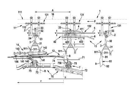
As can be seen in Fig. 1, a lifting apparatus 1 according to the invention
comprises a poultry leg
lifting device 12 and also a carrier lifting device 13 having a carrier
guiding device 132, which is
associated with a poultry leg lifting way h, defined by a portion of a total
conveying way, of the
poultry leg lifting device 12 and is configured to cooperate with a lifting of
the poultry leg 9 passing
through the poultry leg lifting way h.
In order that important parts of the lifting apparatus 1 and the devices
thereof are clearly visible in
the drawing, support, frame and connecting parts, on which members, units,
Date Recue/Date Received 2020-06-15
CA 03070461 2020-01-17
- 8 -
components in general are mounted and connected together, as well as drives,
drive
elements and similar elements, are not shown or are not shown in detail.
The lifting apparatus 1 is equipped with a conveying device 11 which has,
along a straight
conveying line 10, a row of poultry carriers 131 which are suspended at a
uniform height and
generally with a uniform spacing A from a conveying strand 111 and are
conveyed in a
direction of conveyance F by means of a conveying chain 112, for example. This
is a typical
overhead conveyor with poultry carriers 131 conveyed in a loop.
Each poultry carrier 131 has a foot hook-in device 31 which is provided on a
foot carrying
part 3 and is formed with U-shaped hangers 311 adjacent to one another in a
pair in the
direction of conveyance F, whereby a poultry leg 9 can be suspended by its
ankle joint ball
911 in each hanger 311, namely for lateral conveying, that is to say with one
of the two
lateral leg sides between the front side of the leg and the rear side of the
leg leading. In Fig.
1, in each case only a leading carrier hanger 311 of the hanger pair is
provided with a left
poultry leg. The other carrier hanger 311 is usually provided with the other,
right poultry leg of
a bird. Each poultry leg 9 is a part which has been separated completely from
a slaughtered
bird.
The poultry leg lifting device 12, as is known from document WO 2015/117668
Al, to which
reference is made, comprises on the entry side, that is to say upstream, a leg
bending device
7 and, following the leg bending device, downstream, a leg holding and guiding
device 14.
The leg bending device 7 is part of a poultry leg positioning device 70. In
the exemplary
embodiment, the poultry leg positioning device has stationary positioning
elements 71 to 74
extending in the direction of conveyance F and also co-running positioning
elements 75. The
co-running positioning elements 75 are each associated with the conveyed
poultry leg 9, with
which they co-run. A positioning element 72 arranged upstream is a guide path
running with
the poultry leg lifting way h, with which each co-running positioning element
75 is lifted and
brought with a lifting arm 750 into abutment on the thigh on the front leg
side of the laterally
conveyed poultry leg 9. The poultry leg 9 is thereby bent in the region of its
knee joint in
conjunction with the stationary positioning elements 71, 72 and at the start
of the positioning
element 74. In the course of the bending of the poultry leg 9, the poultry leg
is lifted, whereby
the hollow of the knee moves in a defined lifted, upper position against the
positioning
element 74, which has a guiding reference edge extending in the direction of
conveyance F,
at which the poultry leg 9 moves into a vertical reference position.
17684-WO - English
i
CA 03070461 2020-01-17
- 9 -
In the exemplary embodiment, the guiding reference edge merges at a conveying
position R,
which the poultry leg 9 passes in the vertical reference position, into a
holding and guiding
gap 141 of the leg holding and guiding device 14. The guiding reference edge
inserts the
poultry leg 9 in the upper position at the level of its knee joint 93 into the
holding and guiding
gap 141, whereby the poultry leg 9 is suspended, arranged vertically, by the
knee joint in the
holding and guiding gap 141 with the drumstick protruding upwards, as is shown
in Fig. 1. By
means of the poultry leg 9 suspended in the holding and guiding gap 141, the
knee joint 93
thereof on the rear side of the leg is located in a reference position at any
point along the
holding and guiding gap 141. As can be seen in Fig. 1, the poultry leg 9 can
be processed in
that reference position. The leg holding and guiding device 14 is configured
as a processing
device for processing the poultry leg 9. A front-side cutting station 142,
which is arranged on
the entry side, has a cutting means 145, in the form of a circular knife,
which is arranged
above the holding and guiding gap 141. A following rear-side cutting station
143 is equipped
with a cutting means 146, formed by a circular knife, which works above the
holding and
guiding gap 141.
During a general successive lifting of the poultry leg 9 along the poultry leg
lifting way h in the
leg bending device 7 and along a reference conveying way r through which the
poultry leg 9
passes in the raised reference position, the poultry leg 9 is so oriented that
the ankle joint
ball 911 is also lifted with the poultry leg 9 or is and must be in a lifted
position in order to
ensure a defined vertical orientation of the poultry leg 9 during lifting and
then in the lifted
state in particular for processing. For this purpose, the carrier lifting
device 13 having the
carrier guiding device 132 is arranged and configured according to the
invention. The unlifted
poultry leg 9, as long as it is being conveyed upstream before reaching the
poultry leg lifting
device 12, is carried with its entire weight solely by means of the poultry
carrier 131, whereby
the ankle joint ball 911 is in many cases firmly seated, namely in a clamped
or fixed manner,
in the foot hook-in device 31, in the example in the carrier hanger 311. As
the poultry leg 9 is
lifted in the poultry leg lifting way h, the weight load of the poultry leg 9
is transferred to the
lifting co-running positioning element 75 and finally to stationary parts such
as rods and
plates, which form the guiding reference edge, or the holding and guiding gap
141.
According to the invention, the carrier guiding device 132 of the carrier
lifting device 13 is
generally arranged next to the poultry leg lifting device 12, in such a manner
that a lifting
guiding member 4 of the carrier guiding device 132 is associated with a
guiding way f of the
poultry leg lifting way h and covers a portion of that guiding way until the
vertical reference
position is reached, as is shown in Fig. 1. As will be described in detail
below, the lifting
guiding member 4, as a dynamic lifting member, is so configured that it works
in interplay
17684-W0 -English
CA 03070461 2020-01-17
¨ 10 -
with the leg bending device 7 of the poultry leg positioning device 70 during
lifting of the
poultry leg 9.
The poultry carriers 131 are also part of the carrier lifting device 13, each
poultry carrier 131
being formed by a carrier suspension part 2 which is suspended at the same
height from the
conveying device 11, for example from the conveying strand 111 in such a
manner that it is
movable by rolling, and a foot carrying part 3 which is mounted vertically,
preferably
generally telescopically thereon. In the exemplary embodiment, the foot
carrying part 3 is
mounted on the carrier suspension part 2 by means of a sliding bearing 24 in
such a manner
that the foot carrying part 3, for vertical adjustment, is freely movable
vertically in a straight
direction V above a lower stop or blocking position. On the foot carrying part
3 there is
formed the foot hook-in device 31 which, during normal transport of the
poultry leg 9, that is
to say in the suspended position, in which the poultry leg 9 loads the poultry
carrier 131 with
its full weight before it reaches the poultry leg lifting device 12, is in the
lower stop/blocking
position. Furthermore, there is arranged on the foot carrying part 3, in the
exemplary
embodiment at the upper end of a shaft 32, a carrier guiding element 33 which,
as shown in
Fig. 1 in the region of the guiding way f, or the poultry leg lifting way h,
is provided for sliding
engagement with the dynamic lifting guiding member 4 in the direction of
conveyance F, in
order to adjust the height of the foot carrying part 3 during the engagement.
The carrier guiding device 132, as is shown in Fig. 1 in arrangement with the
leg bending
device 7 of the poultry leg positioning device 70, is shown in detail in Fig.
2.
The carrier guiding device 132 has the dynamic lifting guiding member 4, which
is designed
to be symmetrical with all parts with respect to an imaginary vertical
conveying mid-plane
extending in the straight conveying line 10. The carrier guiding device 132
provided
according to the exemplary embodiment is therefore described with reference to
a symmetry
half, wherein the parts belonging to the reference numerals are always to be
understood in
the symmetrical duplicate arrangement. It is generally possible to configure
and provide the
parts of the carrier guiding device without a duplicate arrangement.
A guiding bearing device 42 is arranged in a stationary manner on stationary
frame parts
133, for example on support beams or bars of the apparatus frame (not shown).
The guiding
bearing device 42 is a lifting pivot bearing device 421 having a bearing pivot
axis 422 parallel
to the conveying line 10. A two-sided lever is pivotably mounted about that
axis. A first lateral
lever 423, formed by parallel rod parts, carries the dynamic lifting guiding
member 4 in the
form of a lifting guiding rod 41 extending according to the conveying line 10.
The second
17684=WO - English
=
CA 03070461 2020-01-17
- 11 -
lateral lever 424 carries a counter weight 425 as a restoring weight, which
counteracts the
weight with which the lifting guiding member 4, and thus the first lateral
lever 423, is loaded.
By means of the two-sided lever, the lifting guiding rod 41 is pivotable to
and fro between two
vertical positions, namely a lower stop position 44 and an upper stop position
43 parallel to
the conveying line 10 with intermediate heights.
There are further arranged on the carrier guiding device 132 stationary guides
attached to
the frame parts 133, namely, in the mentioned symmetrical arrangement, a
conveying
guiding member 5 in the form of a horizontal guiding rod for sliding guiding
and, likewise in a
symmetrical arrangement, an unlocking control member 6 in the form of a rod,
wherein the
rods extend with the conveying line 10. The attachment of the conveying
guiding member 5
and the unlocking control member 6 to the frame part 133 is not shown in Fig.
1 but is shown
in Fig. 2.
A guiding length I, belonging to the guiding way f, of the lifting guiding
member 4 is
advantageously generally divided into two portions, namely into an ascending
rising guiding
portion 411 and a following horizontal guiding portion 412 fixed thereto,
which portions are
advantageously, as in the exemplary embodiment, one-piece components of the
lifting
guiding rod 41. In comparison with the horizontal guiding portion 412, the
rising guiding
portion 411 has only a small guiding length associated with a start region of
the poultry leg
lifting way h. Advantageously, the configuration is generally such that, as
shown in Fig. 1 and
2, the depth stop 44 limits the lower guiding position of the horizontal
guiding portion 412 to a
height which, at least, is, for example, level with or above the carrier
guiding elements 33
guided with the conveying guiding members 5. The guided foot carrying parts 3
are then
located along the guiding way f at a downwardly limited lifted suspension
height. As can be
seen in Fig. 1, the lifting guiding member 4 has ¨ as is generally provided ¨
a guiding length I
which, at most, is approximately equal to and in any case smaller than the
conveying
distance A between two successive carrier guiding elements 33 or poultry
carriers 131.
The carrier guiding device 132 designed and arranged according to the
invention cooperates
with the poultry leg positioning device 70 of the poultry leg lifting device
12 in a particular
way. This is generally achieved in that, by means of the guiding bearing
device 42, the lifting
guiding member 4 is dynamically vertically movable by lowering and lifting, in
dependence on
the load with which the poultry carrier 131 in the associated portion of the
poultry leg lifting
way h is loaded or unloaded. The carrier guiding device 132 is so configured
that the
interplay is adjustable in particular in dependence on average weights of
conveyed poultry
17684-WO - English
CA 03070461 2020-01-17
- 12 -
legs 9 and/or on an average leg anatomy or size and is adaptable to lifting
variations, as will
be explained hereinbelow.
As discussed above, the ankle joint ball 911 of a poultry leg 9 at the normal
suspension
height of the foot hook-in device 31 is, as is assumed, clamped in the carrier
hanger 311 as
long as the foot carrying part 3, or the carrier guiding element 33 thereof,
is out of
engagement with the dynamic guiding member 4. Such a conveying position is
shown
upstream in Fig. 1. In Fig. 1, a position is then shown within the poultry leg
lifting way h in
which the poultry leg 9 has been lifted by the co-running positioning element
75, and thus the
ankle joint ball 911, into a position at which the suspension height of the
foot carrying part 3
in engagement with the lifting guiding member 4 has set itself. This is
effected by the
following procedure. On coming into contact with the carrier guiding element
33, which is
guided by means of the conveying guiding member 5 into the carrier lifting
device 13, a first
weight unloading of the foot carrying part 3 occurs. The restoring force can
be so adjusted,
by displacement of the restoring/counter weight 425, that the foot carrying
part 3 is lifted
along the rising guiding portion 411 in order to adapt the suspension height
to the lifting ankle
joint ball 911. This lifting can be accompanied at the same time by a lowering
of the lifting
guiding member 4 by weight loading. In general, lifting can take place to a
greater extent
than lowering. The lifting guiding member 4 is, for example, so configured or
adjusted that it
is movable into a lower guiding position which establishes itself when the
lifting guiding
member 4 is loaded with a weight force greater than the restoring force. Upon
further
unloading of the foot carrying part 3, the lifting guiding member 4 rises and
enters a neutral
floating state, in which the weight load still acting on the foot carrying
part 3 is balanced by
the restoring force.
It is important that the lifting guiding member 4, in the floating state, is
able to tilt or oscillate
to and fro in a floating region around the bearing pivot axis 422. Depending
on the
adjustment of the restoring force, in the exemplary embodiment by means of the
counter
weight 425, the oscillating state can purposively be established at a desired
point in the
region of the poultry leg lifting way h, in order to adapt the floating region
to the lifting region,
in which the poultry leg 9 is successively lifted. Advantageously, the
restoring force can be so
adjusted, by displacement of the counter weight 425, that the lifting guiding
member 4
already assumes a floating guiding position in a carrier insertion position,
in which the foot
carrying parts 3 come into engagement with the lifting guiding member 4. In
particular, the
first lifting then takes place at the start of the poultry leg lifting way h
in combination with the
small rising guiding portion 411 relative to the lifting guiding length. In
principle, the
adjustment takes place in such a manner that the greatest load on the foot
carrying part 3,
17684-WO - English
4
,
CA 03070461 2020-01-17
- 13 -
which occurs at the start of lifting of the poultry leg 9, is largely
neutralised in the course of
the lifting by the restoring force or the counter force. By successive weight
unloading as a
result of the lifting of the poultry leg 9 along the poultry leg lifting way h
of the poultry leg
lifting device 12, the lifting guiding member 4 pivots upwards, so that each
foot carrying part
3 in engagement therewith, and thus the foot hook-in device 31 with carrier
hangers 311, is
successively smoothly lifted to suspension heights which correspond with the
lifted heights of
the ankle joint ball 911 of the poultry leg 9 on passing through the poultry
leg lifting way h.
The maximum lifting height is limited by the stop position 43. An ankle joint
ball 911 clamped
or otherwise fixed in the foot hook-in device 31, in the example in the
carrier hanger 311, is
freely deflected upwards with the guided foot hook-in device 31 upon lifting,
so that
interrupted operation or incorrect positioning upon lifting is reliably
avoided.
In the exemplary embodiment according to Fig. 1, the guiding way f ends at a
point at which
a defined lifted ankle joint ball position has been reached, namely when the
laterally
conveyed poultry leg 9 comes or has come into abutment in the region of its
knee joint 93 on
the guiding reference edge. The guiding reference edge and then the holding
and guiding
gap 141 take over the guiding of the poultry leg 9 and are loaded with the
weight thereof. At
the defined lifted ankle joint ball position, the carrier guiding element 33
comes out of
engagement with the lifting guiding member 4, so that the latter, before it
comes into
engagement with the foot carrying part 3 of the following poultry carrier 131,
is moved back
into a guiding starting position which is determined by the above-described
adjustment of the
restoring force with the desired floating position or stop position.
The lifting apparatus according to the invention is particularly advantageous
when the poultry
leg lifting device 12, as in the exemplary embodiment according to Fig. 1, has
the leg holding
and guiding device 14, which receives the poultry leg 9 at the mentioned
defined lifted ankle
joint ball position for holding and guiding. It remains necessary along the
reference
conveying way r that the ankle joint ball 911, which is clamped or otherwise
fixed in the foot
hook-in device 31, is not impeded by this fixing. Since the ankle joint ball
911 remains at the
height of the defined lifted ankle joint ball position and may also
additionally be lifted,
although only slightly, in the intake region of the guiding reference edge, it
is necessary that
the foot carrying part 3 continues to be upwardly movable unhindered with the
foot hook-in
device 31 in order to ensure corresponding suspension heights, whereby the
lifted ankle joint
ball positions can also vary owing to anatomical structural differences in the
conveyed poultry
legs 9.
17684-WO- English
CA 03070461 2020-01-17
- 14 -
The foot carrying parts 3 of the poultry carriers 131 of the carrier lifting
device 13 according
to the invention remain vertically movable for vertical adjustment even after
leaving the
carrier guiding device 132. The ankle joint balls 911 conveyed along the
reference conveying
way r are already in lifted ankle joint ball positions, the poultry legs 9
being carried and
supported in the region of the knee joint 93. Consequently, the foot carrying
parts 3 are each
completely freed of the weight of the poultry leg 9, with the effect that the
foot carrying parts
3 fit the ankle joint balls 911 with sufficiently smooth vertical movability,
as is shown
downstream in the left-hand half of Fig. 1.
Only when the poultry carriers 131 leave the leg holding and guiding device 14
are they in
each case moved downwards by means of the sliding bearing 24, whereby they
strike a stop
which holds them at the normal suspension height for transport of the poultry
leg 9. By
means of an arresting element 23, such as a locking lever or the like, which
is shown only as
a broken line, the foot carrying part 3 can be fixed preferably automatically
at the normal
suspension height on the carrier suspension part 2. This carrier lock is to be
released before
the poultry carrier 131 comes into engagement with the lifting guiding member
4. For this
purpose, the carrier guiding device 132 is equipped with the guiding elements
6 which come
into engagement with the arresting element 23 in order to unlock it.
The lifting device according to the invention can also be configured for the
axial conveying of
poultry legs which are to be lifted. An example of such a form is shown in
Fig. 3. For identical
or corresponding devices and elements, reference numerals which correspond to
those in
Fig. 1 are used. In this respect, reference is made for the description of the
exemplary
embodiment according to Fig. 3 to the description relating to Fig. 1.
The axial conveying according to Fig. 3 differs from the lateral conveying
according to Fig. 1
in that the foot hook-in device 31 with the double carrier hanger of the
poultry carrier 131 is
rotated through 90 about the shaft 32 of the foot carrier part 3. The left
and right poultry legs
of a bird, separated from the bird, are conveyed with the leg side on which
the patella is
located leading. In Fig. 3, the poultry carriers 131 are shown with only the
left poultry legs 9
being conveyed. Accordingly, for lifting, positioning and processing, only one
poultry leg
lifting device 12 with a poultry leg positioning device 70 and a leg holding
and guiding device
14 for the left poultry legs 9 is shown. Devices which are not shown for
lifting, positioning and
processing the right poultry legs which are also conveyed in parallel by the
poultry carriers
131 are configured correspondingly to the devices for the left poultry legs.
The carrier guiding
device 132 of the carrier lifting device 13 corresponds to the carrier guiding
device 132
shown in Fig. 2, to the description of which reference is made.
17684-WO- English
CA 03070461 2020-01-17
- 15 -
The poultry legs 9, which according to Fig. 3 are conveyed in pairs by the
foot hook-in
devices 31, pass from the normal suspended position, as is shown upstream in
Fig. 3, into
the leg bending device 7 of the poultry leg positioning device 70, which
together form the
poultry leg lifting device 12. The devices 12, 70 and 7 are configured for
bending, lifting and
positioning the poultry legs 9 conveyed axially in pairs. Such an apparatus
for the axial
conveying of the poultry legs in pairs is described in detail in WO
2015/117668 Al, to which
reference has already been made.
.. According to the invention, the carrier guiding device 132 is also
associated in the exemplary
embodiment of axial conveying according to Fig. 3 with the guiding length I
along the guiding
way f of the lifting way h of the leg bending device 7. Bending and
positioning along an
associated portion of the poultry leg lifting way h takes place by means of a
stationary
positioning element 76 having a ramp guide running upwards in the direction of
conveyance
F and having a row of co-running positioning elements 78 each associated with
a poultry leg
9 and each having a positioning arm 780 which engages in the hollow of the
knee of the
poultry leg 9 conveyed with the front side of the leg leading. A stationary
positioning element
77 forms a linear, straight routing. According to the invention, lifting of
the poultry legs 9
along the portion of the lifting way h covered by the guiding way f is
supported and promoted,
the carrier guiding device 132 being so adjustable to the bending and lifting
operation that in
each case the foot hook-in device 31, in specific dependence on the weight
unloading of the
poultry leg 9 during lifting and positioning, passes into suspension heights
which are adapted
to a deflection or lifting of the ankle joint balls 911 during lifting and
positioning.
The holding and guiding gap 141 of the leg holding and guiding device 14 is so
configured
that it receives each poultry leg 9 with the patella leading in the region of
the knee joint,
namely at a conveying point R at which, in the exemplary embodiment, the
portion of the
poultry leg lifting way h that belongs to the leg bending device 7 ends. At
this point, the
carrier guiding device 132 is also left at the end of the guiding way f. The
poultry leg 9 thus
passes into the reference conveying way r, the holding and guiding gap 141
forming
reference edges and the poultry leg 9 passing into the vertical position shown
downstream in
Fig. 3, in which the ankle joint ball 911 is weight-unloaded and further
lifted as a result of the
poultry leg 9 being suspended by the holding and guiding gap 141. As described
hereinbefore in relation to the exemplary embodiment of lateral conveying, the
foot hook-in
device 31 is then seated on the drumstick 91 beneath the ankle joint ball 911,
or the ankle
joint ball 911 is fixed, for example in a clamped manner, on the foot hook-in
device 31.
17684-WO - English
,
,
CA 03070461 2020-01-17
- 16 -
The leg holding and guiding device 14 has a cutting station 147 with a pair of
cutting means
148, formed by circular knives, which are arranged offset along the conveying
way. In the
cutting station 147, cuts are made beneath the holding and guiding gap 141 on
the two
lateral leg sides of the poultry leg 9 at the level of the knee joint. The
cutting station 147 is
followed by further processing stations (not shown) of the leg holding and
guiding device 14.
The invention is not limited to the arrangement of the carrier guiding device
132 of the
exemplary embodiments according to Fig. 1 and 3. In particular, the described
carrier guiding
device 132 can, for example, purposively be associated with an end section of
the leg
bending device 7 and a starting section of the leg holding and guiding device
14. It is
emphasised that the leg holding and guiding device 14 as such also lifts the
poultry leg 9
after it has been threaded into the holding and guiding gap 141. Thus, the
invention also
includes, for example, an arrangement of the carrier guiding device 132 in
which it is
associated only with the leg holding and guiding device 14, in particular a
starting section. It
is also clear that the carrier guiding device according to the invention, for
example in the form
described by means of Fig. 2, can be arranged multiple times in a row one
behind the other
along a conveying way. Two adjacent carrier guiding devices may thereby follow
one another
directly or be spaced apart, depending on the use along the conveying way. In
each case,
the arrangement is defined in that the lifting guiding member 4 has a guiding
length I which,
at most, is equal to the conveying distance A between two successive poultry
carriers 13.
17684-WO - English