Note: Descriptions are shown in the official language in which they were submitted.
CA 03070622 2020-01-21
METHOD AND DEVICE FOR QUANTIFYING VISCOELASTICITY
OF A MEDIUM
TECHNICAL FIELD
[0001] The present disclosure relates to the technical field of
measurement, and in particular,
to a method and a device for quantifying viscoelasticity of a medium.
BACKGROUND
[0002] When performing a vibration excitation on a medium, propagation
characteristics of the
vibration in the medium are related to the viscoelasticity of the medium. By
measuring the
propagation characteristics of the vibration, the viscoelasticity of the
medium can be quantified.
[0003] The above principle has been applied to many technical fields at
present. Taking medical
testing as an example, when testing organs or tissues such as liver, thyroid,
and muscle, lesions can
be located by quantifying the viscoelasticity of the medium.
[0004] Therefore, how to perform efficient and accurate viscoelasticity
quantification of the
medium is a problem to be solved.
SUMMARY
[0005] Embodiments of the present disclosure provide a method and a
device for quantifying
viscoelasticity of a medium. In order to have a basic understanding of some
aspects of the disclosed
embodiments, a brief summary is given below. This summary is neither a general
review, nor
intended to determine key/important constituent elements or to describe the
protection scope of
these embodiments. Its sole purpose is to present some concepts in a
simplified form as a prelude
of the following detailed description.
WSLEGAL \ 070]71 \ 00012 \23942209v2 1
CA 03070622 2020-01-21
[0006] According to a first aspect of the embodiments of the present
disclosure, a method for
quantifying viscoelasticity of a medium is provided, and the method includes:
[0007] obtaining a position-time graph of vibration propagation after
the medium is subjected
to a vibration excitation;
[0008] performing angle projection along each angle within a preset angle
range on the
position-time graph to determine a slope of the position-time graph
corresponding to an angle with
maximum signal energy; and
[0009] obtaining a viscoelasticity parameter of the medium according to
the slope.
[0010] Based on the method, as a first optional embodiment, the
performing angle projection
along each angle within a preset angle range on the position-time graph to
determine a slope of the
position-time graph corresponding to an angle with maximum signal energy,
includes:
[0011] performing integral calculation along each angle within the
preset angle range on the
position-time graph;
[0012] determining an angle with a maximum integral value as a slope
angle of a slope line of
the position-time graph; and
[0013] determining a slope of the slope line using the slope angle.
[0014] Based on the method, as a second optional embodiment, the
performing angle projection
along each angle within a preset angle range on the position-time graph to
determine a slope of the
position-time graph corresponding to an angle with maximum signal energy,
includes:
[0015] calculating a gray-level co-occurrence matrix along each angle
within the preset angle
range for the position-time graph;
[0016] obtaining an image texture feature for each angle;
[0017] determining the angle with the maximum signal energy as a slope
angle of a slope line
of the position-time graph, using the image texture feature; and
[0018] determining a slope of the slope line using the slope angle.
[0019] Based on the method, the first embodiment, or the second
embodiment, as a third
optional embodiment, the method further includes:
[0020] filtering out reflected waves in the position-time graph before
the angle projection.
WSLEGAL 070171 \ 00012 \23942209v2 2
CA 03070622 2020-01-21
[0021] Based on the third embodiment, as a fourth optional embodiment,
the filtering out
reflected waves in the position-time graph, includes: performing direction
filtering on the position-
time graph.
[0022] Based on the method, the first embodiment, or the second
embodiment, as a fifth
optional embodiment, the obtaining a position-time graph of vibration
propagation, includes:
[0023] obtaining the position-time graph of the vibration propagation
along a set vibration
propagation direction.
[0024] According to a second aspect of the embodiments of the present
disclosure, a device for
quantifying viscoelasticity of a medium is provided, and the device includes:
[0025] an image module, configured to obtain a position-time graph of
vibration propagation
after the medium is subjected to a vibration excitation;
[0026] a determining module, configured to perform angle projection
along each angle within
a preset angle range on the position-time graph to determine a slope of the
position-time graph
corresponding to an angle with maximum signal energy; and
[0027] a quantifying module, configured to obtain a viscoelasticity
parameter of the medium
according to the slope.
[0028] Based on the device, as a first optional embodiment, the
determining module includes:
[0029] a calculating sub-module, configured to perform integral
calculation on the position-
time graph along each angle within the preset angle range;
[0030] a determining sub-module, configured to determine an angle with a
maximum integral
value calculated by the calculating sub-module as a slope angle of a slope
line of the position-time
graph; and determine a slope of the slope line using the slope angle.
[0031] Based on the device, as a second optional embodiment, the
determining module includes:
[0032] a calculating sub-module, configured to calculate a gray-level co-
occurrence matrix
along each angle within the preset angle range for the position-time graph;
[0033] a determining sub-module, configured to obtain an image texture
feature of each angle;
determine the angle with the maximum signal energy as a slope angle of a slope
line of the position-
time graph, using the image texture feature; and determine a slope of the
slope line using the slope
WSLEGAL\ 070171 \00012 \23942209v2 3
CA 03070622 2020-01-21
angle.
[0034] Based on the device, the first embodiment, or the second
embodiment, as a third
optional embodiment, the device further includes:
[0035] a filtering module, configured to filter out reflected waves in
the position-time graph
before the angle projection.
[0036] Based on the device, the first embodiment, or the second
embodiment, as a fourth
optional embodiment, the image module obtains the position-time graph of the
vibration
propagation along a set vibration propagation direction.
[0037] According to a third aspect of the embodiments of the present
disclosure, a device for
quantifying viscoelasticity of a medium is provided, and the device includes:
[0038] a memory, storing execution instructions;
[0039] a processor, configured to read the execution instructions to
accomplish the following
operations:
[0040] obtaining a position-time graph of vibration propagation after
the medium is subjected
to a vibration excitation;
[0041] performing angle projection along each angle within a preset
angle range on the
position-time graph to determine a slope of the position-time graph
corresponding to an angle with
maximum signal energy; and
[0042] obtaining a viscoelasticity parameter of the medium according to
the slope.
[0043] The technical solutions provided by the embodiments of the present
disclosure may
include the following beneficial effects:
[0044] the angle with the maximum signal energy in the position-time
diagram is determined
using the angle projection, the angle with the maximum signal energy
corresponds to the slope of
the position-time graph, and the slope of the position-time graph is the
propagation velocity of the
vibration in the medium. Since the propagation velocity of the vibration in
the medium is related
to the viscoelasticity of the medium, the viscoelasticity parameter of the
medium can be
quantitatively calculated after the slope of the position-time graph is
obtained. The embodiments
of the present disclosure do not need to select feature points from the
position-time graph to
WSLEGAL \ 070171 \ 00012 \23942209v2 4
CA 03070622 2020-01-21
calculate the slope of the position-time graph, and is not affected by noise
and has a small
calculation amount, and can efficiently and accurately quantifies the
viscoelasticity of the medium.
[0045] It should be understood that the above general description and
the following detailed
description are merely exemplary and explanatory, and should not limit the
present disclosure.
BRIEF DESCRIPTION OF DRAWINGS
[0046] The drawings herein are incorporated in and constitute a part of
the present specification,
illustrating the embodiments consistent with the present disclosure, and
serving to explain the
principles of the present disclosure together with the description.
[0047] FIG. 1 shows a flow chart of a method for quantifying
viscoelasticity of a medium
according to an exemplary embodiment;
[0048] FIG. 2 shows a flow chart of a method for quantifying
viscoelasticity of a medium
according to an exemplary embodiment;
[0049] FIG. 3 shows a flow chart of a method for quantifying
viscoelasticity of a medium
according to an exemplary embodiment;
[0050] FIG. 4 shows a block diagram of a device for quantifying
viscoelasticity of a medium
according to an exemplary embodiment;
[0051] FIG. 5 is a block diagram of a determining module shown in FIG.
4;
[0052] FIG. 6 shows a block diagram of a device for quantifying
viscoelasticity of a medium
according to an exemplary embodiment; and
[0053] FIG. 7 shows a block diagram of a device for quantifying
viscoelasticity of a medium
according to an exemplary embodiment.
DESCRIPTION OF EMBODIMENTS
[0054] The following description and the drawings sufficiently
illustrate specific embodiments
of the present disclosure to enable those skilled in the art to practice them.
The embodiments
WSLEGAL\ 070171 \ 00012 \23942209v2 5
CA 03070622 2020-01-21
represent only possible variations. Unless otherwise explicitly required,
individual components and
functions are optional, and the order of operations may be varied. Parts and
features of some
embodiments may be included in or replace parts and features of other
embodiments. The scope of
embodiments of the present disclosure includes the entire scope of the claims,
and all available
equivalents of the claims. Herein, the various embodiments may be individually
or collectively
represented by the term "invention", which is for convenience only, and if
more than one invention
is actually disclosed, it is not intended to automatically limit the scope of
the application to any
single invention or inventive concept. Herein, relational terms such as first
and second are used
only to distinguish one entity or operation from another entity or operation,
and do not require or
imply that there is any actual relationship or order between these entities or
operations. Moreover,
the terms "including", "containing" or any other variation thereof are
intended to encompass non-
exclusive inclusion, such that processes, methods, or devices that include a
series of elements
include not only those elements, but also other elements not explicitly
listed. The various
embodiments herein are described in a progressive manner, each embodiment
focuses on the
differences from other embodiments. For the same and similar parts between the
various
embodiments, reference can be made to each other. As for the structures and
products or the like
disclosed in the embodiments, since they correspond to the parts disclosed in
the embodiments, the
description is relatively simple, and reference can be made to the description
of the method part for
the relevant parts.
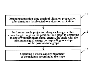
[0055] FIG. 1 shows a flow chart of a method for quantifying
viscoelasticity of a medium
according to an exemplary embodiment. As shown in FIG. 1, the method includes
the following
steps.
[0056] In step 11, obtaining a position-time graph of vibration
propagation after the medium is
subjected to a vibration excitation.
[0057] In step 12, performing angle projection along each angle within a
preset angle range on
the position-time graph to determine an angle with maximum signal energy,
which corresponds to
a slope of the position-time graph.
[0058] The preset angle range refers to an angle range for performing
the angle projection
WSLEGAL\ 070171 \ 00012 \23942209v2 6
CA 03070622 2020-01-21
selected according to actual situations. As an optional implementation, the
preset angle range may
be 360 degree, and accordingly a full-angled angle projection is required to
be performed. As
another optional implementation, the angle range for performing the angle
projection is selected
according to the characteristics of the obtained position-time graph. The
horizontal axis of the
position-time graph obtained in step 11 indicates time and the vertical axis
indicates position. If the
vibration propagates to a distant place only from the starting point of the
vibration excitation, when
the velocity of vibration propagation is infinitely large, it is close to a
straight line parallel to the
vertical axis on the position-time graph, and when the velocity of the
vibration propagation is
infinitely small, it is close to a straight line parallel to the horizontal
axis on the position-time graph.
At this time, a preset angle range of 90 degree can meet the needs, without
the need to perform full-
angle projection, and then the efficiency of quantifying the viscoelasticity
of the medium is
improved. If the vibration can also continue to propagate in an opposite
direction besides
propagating to the distant place from the starting point of the vibration
excitation, the preset angle
range may be 180 degree. As for the actual starting point and ending point of
the preset angle range,
with the rectangular coordinate system remaining unchanged, it is related to
the starting point of 0
degree and the counterclockwise or clockwise rotation direction, which can be
selected as needed,
as long as the preset angle range is guaranteed.
[0059] Each angle refers to each angle within the preset angle range
along which the angular
projection is performed. The selection of specific angle is determined
according to a time accuracy
requirement and a calculation speed requirement. The higher the time accuracy
requirement is, the
higher the accuracy requirement of angle selection is; and the higher the
calculation speed
requirement is, the lower the accuracy requirement of angle selection is. For
example, it can be
selected from 0.01 degree to 1 degree.
[0060] The angle projection refers to performing image feature
recognition or extraction on set
angles to determine an angle with the maximum signal energy.
[0061] In step 13, obtaining a viscoelasticity parameter of the medium
according to the slope.
[0062] The viscoelasticity parameter includes at least one of a
viscosity parameter and an
elastic parameter.
WSLEGAL\ 070171 \000 I 2\23942209v2 7
CA 03070622 2020-01-21
[0063] The slope of the position-time graph is determined by a distance
of vibration
propagation per unit time, that is, the velocity of the vibration propagation
in the medium. In a
homogeneous medium, the velocity of vibration propagation is related to the
viscoelasticity of the
medium. The viscoelasticity parameter of the medium can be quantitatively
calculated after the
slope of the position-time graph is obtained. Therefore, how to efficiently
and accurately obtain the
above slope becomes a key of quantifying the viscoelasticity of the medium. In
the present
exemplary embodiment, the angle with the maximum signal energy is determined
using the angle
projection. Since the angle with the maximum signal energy corresponds to the
slope of the
position-time graph, that is, it is equivalent to obtain the slope of the
position-time graph. This
method does not need to select a peak, a trough, or a certain phase of
vibration from the position-
time graph as a feature point to calculate the slope of the position-time
graph. It is not affected by
noise and has a small calculation amount. It is an efficient and accurate
method for quantifying the
viscoelasticity of the medium.
[0064] In an exemplary embodiment, after performing the vibration
excitation on the medium
through mechanical vibration, acoustic radiation force, or other manners
capable of generating
vibration, the medium generates vibration, and the vibration propagates in the
medium. Due to the
limited propagation velocity of the above vibration in the medium, a detection
wave can be used to
perform dynamic imaging for the medium. The above detection wave may be a
light wave, an
ultrasonic wave, or the like. The above dynamic imaging may be one-dimensional
imaging, two-
dimensional imaging, or three-dimensional imaging.
[0065] When the above-mentioned vibration propagates in the medium, the
wave-front will
reach different positions along the propagation direction at different times.
The echo signal
generated for the imaging of the medium by the detection wave will undergo
phase decorrelation.
Utilizing this characteristic of phase decorrelation, motion information of
the medium can be
obtained through algorithms such as cross-correlation, autocorrelation, and
optical flow. The
position-time graph can be obtained along the set vibration propagation
direction. The above
algorithms may be various methods based on block matching or non-block
matching. The above
set vibration propagation direction is an actual propagation direction of the
vibration when the
WSLEGAL070171 \ 00012 \ 23942209v2 8
CA 03070622 2020-01-21
vibration propagates in only one propagation direction, and is a selected
propagation direction when
the vibration propagates in multiple propagation directions. For example, when
the medium is a
uniform sheet, after the medium is excited by vibration, the vibration will
propagate along the
extension direction of the sheet, and the set vibration propagation direction
at this time is an actual
propagation direction of the vibration. For another example, when the medium
has a stereoscopic
irregular shape, the wave-front of the vibration propagation has a three-
dimensional shape (for
example, the wave-front of the vibration propagation is an ellipsoid), then
different position-time
graphs are obtained along different vibration propagation directions, and the
set vibration
propagation direction at this time is a selected propagation direction of
interest. The above-
mentioned propagation direction of interest is determined according to a
direction that needs to be
actually measured, for example, it may be at least one of a direction in which
the vibration
propagates fastest, a direction in which the vibration propagates slowest, and
a direction in which
the velocity of the vibration propagation is within a certain range.
[0066] In an exemplary embodiment, when the vibration propagates in the
medium, reflected
waves are generated when the vibration encounters edges of the medium or
foreign objects. To
improve the accuracy of subsequent processing, as shown in FIG. 2, before
performing the angle
projection, the method may also include step 11', that is, filtering out the
reflected waves in the
position-time graph. There are many ways to filter out, and direction
filtering is one implementation
of them.
[0067] In an exemplary embodiment, determining the angle with the maximum
signal energy
through the angle projection, and then obtaining the slope of the position-
time graph, can be
implemented through integral calculation. For example, integral calculation is
performed along
each angle within the preset angle range on the position-time graph. When an
integral angle is
consistent with the vibration propagation direction, the energy is gathered,
and the obtained integral
.. value at this time is maximum. Therefore, the angle with the maximum
integral value is determined
as the slope angle of the slope line of the position-time graph. The slope of
the slope line of the
position-time graph can be obtained according to the obtained slope angle,
combined with position
and time information. The above integral calculation is also referred to as
Radon transform.
WSLEGAL\ 070171 \ 00012 \ 23942209v2 9
CA 03070622 2020-01-21
[0068] In an exemplary embodiment, since an image texture feature can be
obtained by
calculating a gray-level co-occurrence matrix, and the image texture feature
can reflect the
magnitude of the signal energy, the gray-level co-occurrence matrix can be
used to obtain
information of the angle with the maximum signal energy. Based on the above
principle,
determining the angle with the maximum signal energy through the angle
projection, and then
obtaining the slope of the position-time graph, can be implemented by
calculating the gray-level
co-occurrence matrix. For example, for the position-time graph, a gray-level
co-occurrence matrix
is first calculated along each angle within the preset angle range. Then, the
image texture feature
of each angle is obtained using the gray-level co-occurrence matrix. Then, the
angle with the
maximum signal energy is determined as the slope angle of the slope line of
the position-time graph
by using the image texture feature. Finally, the slope angle is determined
using the slope angle.
[0069] According to the principle of mechanics, the viscoelasticity of
the medium determines
the propagation velocity of the vibration therein. Therefore, the propagation
velocity of the
vibration in the medium can be learned by obtaining the slope of the position-
time graph. And then
the viscoelasticity parameter of the medium can be quantitatively obtained
according to the
principle of mechanics. The viscoelasticity parameter here may include shear
modulus, Young's
modulus, shear viscoelasticity, shear viscosity, mechanical impedance,
mechanical relaxation time,
anisotropy, and the like.
[0070] The application of the method for quantifying viscoelasticity of
a medium in the
embodiments of the present disclosure will be given in a specific application
scenario.
[0071] When a non-destructive viscoelasticity testing is performed on a
viscoelastic medium
such as human liver, the viscoelasticity of the medium needs to be quantified.
A testing apparatus
includes an exciting device and an imaging device, where the exciting device
performs a vibration
excitation on the medium to be detected, and the imaging device utilizes
ultrasound to perform
imaging for the medium after the vibration excitation. When the vibration
propagates in the medium,
the wave-front will reach different positions along the propagation direction
at different times,
forming a position-time graph. The above wave-front may be one of a peak, a
trough, or the same
phase of vibration.
WSLEGAL\ 070171 \ 00012 \23942209v2 10
CA 03070622 2020-01-21
[0072] As shown in FIG. 3, the method for quantifying viscoelasticity of
a medium in this
specific application scenario may include the following steps.
[0073] In step 31, performing a vibration excitation on the medium.
[0074] In step 32, performing dynamic imaging for the medium using
ultrasound.
[0075] In step 33, obtaining a position-time graph of vibration propagation
from the imaging
of the medium.
[0076] In step 34, performing direction filtering on the position-time
graph.
[0077] In step 35, performing a Radon transform to determine a slope of
the position-time
graph.
[0078] In step 36, calculating a viscoelasticity parameter of the medium
according to the
determined slope and principle of mechanics.
[0079] In various exemplary embodiments of the above method for
quantifying viscoelasticity
of a medium, when there are at least two set vibration propagation directions,
one position-time
graph is obtained for each set vibration propagation direction
correspondingly, and then the
viscoelasticity parameter of the medium corresponding to the position-time
graph is obtained. By
synthesizing the obtained at least two sets of viscoelasticity parameters, the
viscoelasticity of the
medium can be evaluated more comprehensively.
[0080] The various exemplary embodiments of the method for quantifying
viscoelasticity of a
medium given above may be combined according to circumstances, and the
combination
relationship between the various exemplary embodiments is not limited here.
[0081] FIG. 4 is a block diagram of a device for quantifying
viscoelasticity of a medium
according to an exemplary embodiment. The device may be located in a control
host of an apparatus
for testing viscoelasticity of a medium, for example, in a control host of a
non-destructive testing
apparatus for liver in the medical testing field. The device can also be
located in a cloud, and testing
data of the apparatus for testing viscoelasticity of a medium needs to be
processed in the cloud.
[0082] The device shown in FIG. 4 includes an image module 41, a
determining module 42
and a quantifying module 43.
[0083] The image module 41 is configured to obtain a position-time graph
of vibration
WSLEGAL\070171\00012\23942209v2 11
CA 03070622 2020-01-21
propagation after the medium is subject to a vibration excitation.
[0084] The determining module 42 is configured to perform angle
projection along each angle
within a preset angle range on the position-time graph to determine an angle
with maximum signal
energy. The angle with the maximum signal energy described above corresponds
to a slope of the
position-time graph.
[0085] The quantifying module 43 is configured to obtain a
viscoelasticity parameter of the
medium according to the slope of the position-time graph.
100861 In an exemplary embodiment, as shown in FIG. 5, the determining
module 42 employs
a Radon transform to perform the angle projection and determines the angle
with the maximum
signal energy. At this time, the determining module 42 includes a calculating
sub-module 421 and
a determining sub-module 422.
[0087] The calculating sub-module 421 is configured to perform integral
calculation along each
angle within the preset angle range on the position-time graph.
[0088] The determining sub-module 422 is configured to determine an
angle with a maximum
integral value calculated by the calculating sub-module 421 as a slope angle
of a slope line of the
position-time graph; and determine a slope of the slope line of the position-
time graph through the
slope angle.
[0089] As an optional implementation, when a gray-level co-occurrence
matrix is used to
determine the slope angle, the calculating sub-module 421 may be configured to
calculate the gray-
.. level co-occurrence matrix along each angle within the preset angle range
for the position-time
graph. The determining sub-module 422 may be configured to obtain an image
texture feature of
the each angle; determine the angle with the maximum signal energy as a slope
angle of a slope
line of the position-time graph using the image texture feature; and determine
a slope of the slope
line using the slope angle.
[0090] In an exemplary embodiment, as shown in FIG. 6, the device for
quantifying
viscoelasticity of a medium further includes: a filtering module 44,
configured to filter out reflected
waves in the position-time graph before the determination module 42 performs
the angle projection.
[0091] In an exemplary embodiment, the image module 41 obtains the
position-time graph of
WSLEGAL \ 070171 \ 00012 \23942209v2 12
CA 03070622 2020-01-21
the vibration propagation along a set vibration propagation direction.
[0092] The application of the device for quantifying viscoelasticity of
a medium in the
embodiments of the present disclosure is given in a specific application
scenario.
[0093] When performing a non-destructive viscoelasticity testing on a
viscoelastic medium
such as human liver, the viscoelasticity of the medium needs to be quantified.
A testing apparatus
includes an exciting device and an imaging device, where the exciting device
performs a vibration
excitation on the medium to be detected, and the imaging device utilizes
ultrasound to perform
imaging for the medium after the vibration excitation.
[0094] When the vibration propagates in the medium, the wave-front will
reach different
positions along the propagation direction at different times, forming a
position-time graph. The
above wave-front may be one of a peak, a trough, or the same phase of
vibration. The device for
quantifying viscoelasticity of a medium obtains the position-time graph of the
vibration
propagation from the imaging of the medium along the set propagation
direction. Then the device
for quantifying viscoelasticity of a medium performs integral calculation
along each angle on the
position-time graph, and determines the angle with the maximum integral value
as the slope angle
of the slope line of the position-time graph, and then determines the slope of
the position-time
graph. Finally, the device for quantifying viscoelasticity of a medium
calculates and obtains the
viscoelasticity parameter of the medium according to the determined slope and
principle of
mechanics.
[0095] FIG. 7 is a block diagram of a device for quantifying
viscoelasticity of a medium
according to an exemplary embodiment. The device may be located in a control
host of an apparatus
for testing viscoelasticity of a medium, for example, in a control host of a
non-destructive testing
apparatus for liver in the medical testing field. The device can also be
located in a cloud, and testing
data of the apparatus for testing viscoelasticity of a medium needs to be
processed in the cloud.
[0096] The various exemplary embodiments of the device for quantifying
viscoelasticity of a
medium given above may be combined according to circumstances, and the
combination
relationship between the various exemplary embodiments is not limited here.
[0097] The device shown in FIG. 7 includes: a memory 71 and a processor
72.
WSLEGAL \ 070171 \ 00012 \23942209v2 13
CA 03070622 2020-01-21
[0098] The memory 71 stores execution instructions.
[0099] The processor 72 is configured to read the execution instructions
from the memory 71
to execute some or all steps in the exemplary embodiments of the method for
quantifying
viscoelasticity of a medium described above. The processor 72 may be
implemented by a chip.
[0100] If the device for quantifying viscoelasticity of a medium shown in
FIG. 7 is located in
the control host of the apparatus for testing viscoelasticity of a medium, it
can be connected to an
exciting device and an imaging device in the apparatus for quantifying
viscoelasticity of a medium
by bus, wireless, etc. At this time, the device has interfaces to realize the
above connections and
corresponding communication mechanism.
[0101] If the device for quantifying viscoelasticity of a medium shown in
FIG. 7 is located in
the cloud, it can communicate with the apparatus for testing viscoelasticity
of a medium through a
network.
[0102] It should be understood that the present disclosure is not
limited to the processes and
structures that have been described above and shown in the drawings, and
various modifications
and changes can be made without departing from the scope thereof. The scope of
the present
disclosure is only limited by the appended claims.
wSLEGAL\070 I 71 \ 00012 \23942209v2 14