Note: Descriptions are shown in the official language in which they were submitted.
CA 03070806 2020-02-03
Preparation station for a fast food restaurant
Description
The invention relates to a station for covering a bread roll half of a
bread roll with a sauce in a preparation line of a fast food restaurant.
Stations for covering a bread roll half of a bread roll with a sauce in a
preparation line of a fast food restaurant are conventionally operated
using purely manually actuable cartridge dispensing devices, such as
are known from CA 2 930 097 Al, US 2012/0228334 Al or US
2016/0332788 Al.
The object of the invention is to improve the known stations.
This object is achieved by the features of the independent claim.
Preferred configurations and developments are described in the
dependent claims.
1
CA 03070806 2020-02-03
In one aspect of the invention, a station for covering a bread roll half of
a bread roll with a sauce in a preparation line of a fast food restaurant
comprises a table having an input side for receiving the bread roll half,
an output side which is opposite the input side for outputting the bread
roll half covered with sauce, a front side connecting the input side and
the output side, it being possible for a user standing at said front side to
cover the bread roll half with the sauce, and a rear side opposite the
front side, a container comprising the sauce and arranged over the
table at a working distance from the front side and from which an outlet
.. nozzle oriented towards the table protrudes at a vertical distance from
the table so that the bread roll half which is to be covered with sauce
can be placed on the table below the outlet nozzle, and a pressure
actuator that can be actuated by the user and which is designed to
dispense the sauce from the container onto the bread roll half when
.. actuated by the user.
The specified station is subject to the consideration that the manually
actuable cartridge dispensing devices are comparatively resource-
intensive. If, after use, the user places the cartridge dispensing device
back in a container provided therefor, a large amount of residual sauce
located on the output nozzle will always drip off as a result of the
shaking. At several thousand uses per day, this results in a high sauce
wastage.
For the specified station, it is proposed to mount the cartridge
dispensing device rigidly. As a result of the rigid mounting, the cartridge
2
CA 03070806 2020-02-03
dispensing device cannot be shaken, and this leads to much less
residual sauce dripping off when the bread roll half is being covered.
In a development of the specified station, the container comprises a
packet having a movable base that is inserted into a receiving space of
a base body, a movable rod being guided from the outer face of the
base body into the receiving space and a pivotable lever, mounted on
the base body, being in engagement with the rod so as to push the rod
in the direction of the receiving space as soon as the lever is pivoted
with respect to the base body.
In a further development, the specified station comprises an actuator
that connects the lever to the base body and that is set up to pivot the
lever with respect to the base body.
In another further development of the specified station, the actuator is a
pneumatic actuator.
In a preferred development of the specified station, the pneumatic
actuator comprises a pneumatic cylinder having a cylinder body and a
piston that is movable under pressure in the cylinder body and that has
a piston rod.
In a particularly preferred development of the specified station, the
pneumatic cylinder is connected in a stationary manner to the base
body and the movable piston thereof is connected to the lever.
3
CA 03070806 2020-02-03
In another development, the station comprises an attachment that is
removably attached to the lever and to which the actuator is pivotably
connected.
In another further development of the specified station, the base body
comprises a base plate having a lower face for placing the base body
on and an upper face opposite the lower face, the receiving space
being arranged adjacent to the upper face.
In an additional development of the specified station, the actuator is
arranged pivotably on the base plate.
In a particular development of the specified station, the receiving space
has a semicylindrical outer face in which a piston plate coupled to the
.. rod is guided.
In a further development, the specified station has a handle fixed in a
stationary manner to the base body, the lever being arranged pivotable
towards the handle to push the rod in the direction of the receiving
space.
In another further development, the specified station comprises at least
one further container comprising a further sauce and arranged over the
table at a working distance from the front side and from which a further
.. outlet nozzle oriented towards the table protrudes at a further vertical
distance from the table, and a further pressure actuator that can be
actuated by the user and which is designed to dispense the sauce from
the further container when actuated by the user.
4
CA 03070806 2020-02-03
In a preferred development of the specified station, the pressure
actuator and the further pressure actuator can be actuated by way of a
shared actuation member.
In a particularly preferred development of the specified station, the base
body, the lever and the rod are part of a gun device that are insertable
into the container.
In another further development of the specified station, the table
comprises a clearance below the outlet nozzle.
In another aspect of the invention, a device comprises a base body
having a receiving space for inserting a packet containing the foodstuff,
a movable piston rod that is guided into the receiving space from the
outside of the base body, and a pivotable lever that is mounted on the
base body and in engagement with the piston rod for pushing the piston
rod in the direction of the receiving space as soon as the lever is
pivoted with respect to the base body, an actuator that connects the
lever to the base body being provided and being arranged so that it
pivots the lever with respect to the base body. As a result of the
actuator, the user virtually no longer has to apply any force so as to
dispense a foodstuff from the packet, and so the device can be used
more easily, and above all also multiple times in succession, without the
use thereof leading to muscle ache or excessive fatigue. High forces
can also be applied using the lever so as to push the foodstuff out of the
packet reliably. It is also advantageous that unappetizing residues of
the foodstuff, which easily adhere to the output opening and soil an
output connector, virtually do not occur, since the output always takes
5
CA 03070806 2020-02-03
place vertically downwards and the packet also always remains in the
vertically downwardly oriented position of the output opening thereof.
Preferably, the actuator is a pneumatic actuator. In this case, the
pneumatic actuator has a pneumatic cylinder having a cylinder body
and a piston that is movable pneumatically relative to the cylinder body.
In this context, the cylinder body is connected in a stationary manner to
the base body of the device and the movable piston is connected to the
lever. Thus, only the comparatively small piston has to be moved, while
the cylinder body having the larger mass remains stationary. The mass
to be moved, which is thus lower, is also noticeable by way of a lower
power consumption.
Also preferably, the actuator may be an electric drive, such as an
electric motor having a spindle drive or an electromagnet having a
piston rod. In this context, it should in each case be ensured that after
each stroke of the piston rod the drive returns to a predefined starting
position, it being possible for this to take place by spring force in the
case of the electromagnet having a piston rod, and either by reversal of
the direction of rotation of the electric motor or by decoupling of the
spindle drives from the electric motor in the case of the electromagnet
having a spindle drive.
Preferably, the device comprises an end piece that is releasably
attached to the lever and on which the actuator is pivotably held. As a
result, the actuator can be removed from the lever in a simple manner,
making it possible, without any major steps, to retrofit the device so that
it can also be used with pure manual operation.
6
CA 03070806 2020-02-03
Preferably, the base body comprises a base plate having a lower face
for placing the base body on and an upper face opposite the lower face,
the receiving space for inserting the packet being arranged adjacent to
the upper face. Using the base plate, the device can easily be fixed to
the underlying surface, such as a table. Preferably, in this context, the
base plate is held at a distance from the upper face of the table so that
output of the foodstuff can take place vertically downwards.
The actuator is arranged pivotably on the base plate. A tubular
receiving space is formed in the base body and opens towards an outer
face in a radial direction that differs from a radial direction in which the
lever extends.
Preferably, the device comprises a support handle fixed in a stationary
manner on the base body, the lever being arranged pivotable towards
the support handle for pushing the rod in the direction of the receiving
space.
Normally, the lever is directed in the same direction in which the user
inserts the packet into the receiving space and withdraws the dispensed
sauce from the packet. In the device according to the invention,
however, the lever is directed in the other direction. In this way, the user
has more space in front of the specified device. Equally, in emergency
operation, purely manual operation using the lever is also possible from
the rear side.
Preferably, a plurality of devices of the aforementioned type is arranged
in a row in a shared housing. Thus, a plurality of different foodstuffs,
7
CA 03070806 2020-02-03
such as ketchup, hot mustard, mild mustard, mayonnaise, sauce,
dressing or other condiments, can be offered to customers at one
station.
Hereinafter, the invention is explained in greater detail with reference to
embodiments in connection with the drawings, in which:
Fig. 1 is a side view of the sauce dispenser according to the invention;
Fig. 2 is a view of the rear side of the sauce dispenser of Fig. 1;
Fig. 3 is a side view rotated through 1800 of the sauce dispenser
of Fig. 1;
Fig. 4 is a side view rotated through 180 of the sauce dispenser of Fig.
2;
Fig. 5 is a schematic view of an arrangement of a plurality of sauce
dispensers according to the invention;
Fig. 6 is a view of the sauce dispensers of Fig. 5 seen from one side;
Fig. 7 is a perspective view of a station for covering a bread roll half
of
a bread roll with a sauce;
Fig. 8 is a front view of the station of Fig. 7;
Fig. 9 is a sectional view of the station of Fig. 7 and 8; and
Fig. 10 shows the station of Fig. 7 to 9 in a preparation line of a fast food
restaurant.
In the drawings, like technical elements are provided with like reference
numerals and are only described once. The drawings are purely
schematic and in particular do not reproduce the actual geometric
relationships.
8
CA 03070806 2020-02-03
Reference is made to Fig. 1 to 4, which are four side views of a
device for covering a bread roll half of a bread roll with a sauce. The
device has a base body having two parallel side walls 1 and 2, a
cover wall 3 and a base plate 4, which enclose a receiving space 5.
A packet (not shown) comprising a paste-like foodstuff, such as a
sauce, can be inserted into the receiving space 5. The receiving
space 5 is adapted to the shape of the packet and provided with a
circular lid 6. A rod 7, which carries a piston plate 8 at the end thereof
in the receiving space 5, protrudes through the lid. The other end of
the rod 7 protrudes through the cover wall 3 and ends with a
handle 9, which may be colored to identify the paste-like foodstuff.
The rod 7 and the piston plate 8 fixed thereto are guided, linearly
displaceably in the longitudinal direction, in an opening in the lid 6
and in a further opening in the cover wall 3.
Further, the rod 7 is coupled to a pivotable lever 10, the lever 10 being
held directly or indirectly on the two side walls 1 and 2 via a pivot
= 20 joint 11. A drive pin 10a on the lever 10 is coupled to a drive
plate 12,
which is biased by a spring 13 and which encloses the rod 7. During the
upward movement of the lever 10, the drive plate 12 tilts with respect to
the rod 7 and thus pushes the rod 7 downwards, whereas during the
downward movement of the lever 10, the drive plate 12 is brought by
the spring 13 into a tilt-free position in which it slides along the rod 7
without moving the rod 7. In this way, by repeated movement of the
lever 10 in both directions, the rod 7 is incrementally pushed
downwards, causing the piston plate 8 to be pushed onto a movable
9
CA 03070806 2020-02-03
base of the packet and making it possible to dispense a predetermined
amount of the paste-like foodstuff from the packet on each stroke.
The lever 10 is moved in the upward movement direction and in the
downward movement direction by way of an actuator implemented as a
pneumatic cylinder 14, of which one end is connected to the base
plate 4 and the other end is connected to the lever 10, an articulated
connection to joints 15a and 15b respectively being provided at the two
ends.
In the embodiment shown in Fig. 1 to 4, the pneumatic cylinder 14 is
connected to the base plate 4 via a joint 15a and has a displaceable
piston rod 16 which is articulated to the free end of the lever 10. The
pneumatic cylinder 14 can be activated by way of a pneumatic
switch 17, which is attached to one of the side walls 1 or 2 or an end
wall, specifically preferably so that it faces the withdrawal side of the
device shown at which a user uses the device for covering the bread
roll half of the bread roll with the sauce. By pushing the switch 17
towards the packet, a pneumatic line 20 is opened and compressed air
is thus applied to the pneumatic cylinder 14. Thereupon, the pneumatic
cylinder actuates the lever 10, which in turn pushes the piston rod 16
downwards, in such a way that the paste-like foodstuff is pushed out of
the packet. If the switch 17 is released, the pneumatic cylinder 14 is
pressure-free again, and the piston rod 16 is slid in the direction of the
interior of the pneumatic cylinder 14 by a restoring spring (not shown in
greater detail), so that the lever 10 is displaced back into the starting
position thereof again, but without moving the rod 7. With each
actuation of the switch 17, the pneumatic cylinder 14 thus performs the
CA 03070806 2020-02-03
aforementioned stroke, a predetermined amount of the paste-like
foodstuff thus being pushed out of the packet.
The piston rod 16 is connected to a free end of the lever 10 via an
attachment 18. In this context, the piston rod 16 is thus linked to the
attachment 18 via a pivot joint 15b. Since the lever 10 is fixed in the
upper region of the housing via the pivot joint 11 and inclined
substantially obliquely downwards in the direction towards the base
plate 4, the attachment 18 can simply be placed on the free end of the
lever 10 and held in a frictional fit, since only minimal longitudinal forces
occur in the direction of the longitudinal axis of the lever 10 when the
piston rod 16 moves. Thus, if the pneumatics fail, the attachment 18
can be removed from the free end of the lever 10 without difficulty, so
that the lever 10 can be actuated by hand. For this purpose, a
stationary support handle 19, on which a hand can rest when the
lever 10 is actuated, is fixed on the housing.
Compressed air is supplied to the pneumatic cylinder 14 via the
aforementioned pneumatic line 20 and an upstream valve 21, which are
connected to a compressed air source (not shown).
In the embodiments described thus far, the actuator is a pneumatic
cylinder that has a piston rod and that is pneumatically operated using
air pressure. Alternatively, an electromagnetic actuator may also be
used, which actuates the piston rod 16 analogously, in which case it
should still be provided that the piston rod 16 travels out when the
switch 17 is being actuated and automatically travels back into the
starting position thereof, for example under spring force, when the
switch 17 is not being actuated.
11
CA 03070806 2020-02-03
As can be seen most clearly from Fig. 4, the base plate 4 is in a raised
position with respect to an underlying surface, such as a table, so that
the sauce can be outputted vertically downwards under the base
plate 4. This raised position is ensured by two parallel supporting
walls 26 in this case. It can also be provided by feet (not shown) or in
some other way.
Fig. 5 schematically shows an arrangement of a plurality of devices of
the described type, which are accommodated in a row in a shared
housing. In this specific case, there are eight receiving spaces, the
rods 7 being depicted in this drawing with the handles 9 in their
extended upper position, in which a packet can be inserted into the
receiving space in each case. At the position of each of rods 7, the fill
level of the associated packet can also immediately be discerned from
the outside. A switch 17 is provided for actuating each individual sub-
device. In this case too, the output takes place downwards, so that the
base plate 4 is held at a distance from a table 22, in this case by a
supporting wall 23.
It can also further be seen from Fig. 5 and 6 how a combined device
can be arranged in a restaurant and integrated into a counter 25.
In the embodiment of Fig. 5, the receiving spaces 5 are open in part, so
that the user can see the associated packets. Naturally, it is also
possible to seal off the side facing the user with a plate (not shown).
The contents of the individual packets can be identified by coloring
12
CA 03070806 2020-02-03
and/or labeling the handles 9 or by labeling the narrow front wall 22
bearing the switch 16.
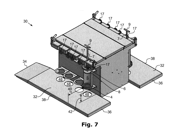
Reference is made to Fig. 7 to 9, which show a station 30 for covering a
bread roll half of a bread roll with a sauce in a preparation line of a fast
food restaurant.
The station comprises a table 32 having an input side 34 for receiving
the bread roll half, an output side 36 which is opposite the input side 34
for outputting the bread roll half covered with sauce, a front side 38
connecting the input side 34 and the output side 36, it being possible for
a user standing at said front side to cover the bread roll half with the
sauce, and a rear side 38 opposite the front side 38, against which an
arrangement of a plurality of the above-described devices, for example
according to Fig. 5, is positioned. A container comprising the sauce and
arranged at a working distance 40 from the front face leads over the
table 32, from which container an outlet nozzle directed towards the
table 32 protrudes at a vertical distance 42 from the table 32, so that the
bread roll half to be covered with the sauce can be placed on the table
below the outlet nozzle. The container comprising the outlet nozzle is
part of the aforementioned packet (not shown in greater detail).
The packet is inserted into a device as described above. Alternatively,
.. the device may also be constructed as a manual cartridge dispensing
device, also known as a gun device, such as is described for example
in CA 2 930 097 Al and US 2012/0228334 Al. In this case, the lever 10
of the device or cartridge dispensing device is moved via an
13
CA 03070806 2020-02-03
intermediate lever 44, which is mounted rotatably at a lever point 46
and which is in turn driven by the piston rod 16 of the pressure
cylinder 14 in the aforementioned manner.
Clearances 48, in which excess residual sauce can be captured if it
drips off unintendedly during operation, are included in the table 32.
14