Note: Descriptions are shown in the official language in which they were submitted.
CA 03070836 2020-01-22
WO 2019/021273 PCT/IL2018/050809
SYSTEMS AND METHODS FOR HEAT EXCHANGE
CROSS REFERENCE
[0001] This application claims priority to U.S. Provisional Application No.
62/535,912, filed on
July 23, 2017, which is entirely incorporated herein by reference.
BACKGROUND
[0002] A problem in the electronics and computer field is increased heat
generation as
computing performance increases. The trend toward ever increasing heat
dissipation in
microprocessor and amplifier based systems, such as those housed in
telecommunication
cabinets, server rooms (data center), and Cloud Computing centers, is becoming
increasingly
critical to the electronics industry. Thus, finding effective thermal
solutions is of interest to
reduce system costs and to increase performance.
[0003] Traditional refrigeration systems for cooling either cool the entire
electronic system or
the heat-generating components therein. Cooling technologies may be used to
cool devices,
device clusters, subassemblies, and cabinet or rack levels, all of which are
within the original
equipment manufacturers' (OEM's) products. Cooling of electric systems and
devices may be
further complicated because, in many cases, thermal regulation is added after
manufacture of
electronic systems and devices and are not considered in the system designs by
the OEM.
Equipment design may utilize the latest software or implement the latest
semiconductor
technology, but the thermal management architecture is generally relegated to
the "later phases"
of the new product design. As such, thermal management issues, associated with
a designed
electronic system, are often solved by the expedient of a secondary cooling or
refrigeration
system that is arranged in tandem with the electronics system.
SUMMARY
[0004] As recognized herein, finding effective thermal solutions for thermal
regulation and
management of electronic systems may be of interest to reduce cost and provide
increased
performance. The present disclosure provides cost effective and continuously
operating thermal
regulation and management of electronic devices or systems. This may be
useful, for example, in
regulating and maintaining a temperature of a source of thermal energy (e.g.,
heat source), such
as, e.g., high power electronic systems and server rooms.
[0005] In an aspect, the present disclosure provides a cooling system,
comprising: a first channel
that is configured to direct a liquid coolant; a second channel that is
configured to direct a vapor
coolant generated from the liquid coolant; a condenser that is configured to
permit the vapor
1
CA 03070836 2020-01-22
WO 2019/021273 PCT/IL2018/050809
coolant to undergo phase transition to the liquid coolant; and at least one
cooling interface in
fluid communication with the first channel and the second channel, wherein the
at least one
cooling interface comprises (i) a coolant inlet for directing the liquid
coolant from the first
channel towards the second channel; (ii) at least one heat exchange unit for
permitting heat to
flow from a source of thermal energy to the liquid coolant from the coolant
inlet, thereby
permitting the liquid coolant to undergo phase transition to the vapor
coolant; and (iii) a coolant
outlet comprising an outlet shut-off valve to permit the vapor coolant to
controllably flow from
the at least one heat exchange unit to the second channel.
[0006] In some embodiments, the system further comprises a flow generator in
fluid
communication with the first channel or the second channel. In some
embodiments, the system
is operated at a pressure of less than about 1 atmosphere. In some
embodiments, the outlet shut-
off valve is an electric or mechanical valve. In some embodiments, the system
is self-regulating.
In some embodiments, the system further comprises a control unit in
communication with the
outlet shut-off valve, condenser, flow generator, or any combination thereof.
In some
embodiments, the system further comprises a pressure regulator in fluid
communication with the
first channel, second channel, condenser, at least one cooling interface, or
any combination
thereof. In some embodiments, the pressure regulator controls a flow rate of
the liquid coolant
and/or the vapor coolant.
[0007] In some embodiments, the at least one cooling interface comprises two
or more
individual cooling interfaces. In some embodiments, the at least one cooling
interface comprises
two or more cooling interfaces, and wherein the two or more cooling interfaces
are connected in
series. In some embodiments, the at least one cooling interface comprises two
or more cooling
interfaces, and wherein the two or more cooling interfaces are connected in
parallel. In some
embodiments, the two or more cooling interfaces share the outlet shut-off
valve. In some
embodiments, the two or more cooling interfaces do not share the outlet shut-
off valve.
[0008] In some embodiments, the cooling interface has a surface area of less
than about 25
square centimeters. In some embodiments, the at least one cooling interface is
in direct contact
with the source of thermal energy. In some embodiments, the at least one
cooling interface is in
indirect contact with the source of thermal energy. In some embodiments, the
system further
comprises an orifice in fluid communication with the first channel or the
second channel. In
some embodiments, the orifice aids with creating a vacuum within the at least
one cooling
interface. In some embodiments, the system provides on demand cooling to the
source of thermal
energy by controlling an amount of coolant in the at least one cooling
interface.
2
CA 03070836 2020-01-22
WO 2019/021273 PCT/IL2018/050809
[0009] In some embodiments, the liquid coolant vaporizes between about 5 C
and about 60 C.
In some embodiments, the system further comprises an expansion container, one
or more
splitters, a user interface, a thermocouple, a transmitter, a processor and a
memory, or any
combination thereof. In some embodiments, the first channel, second channel,
condenser, and at
least one cooling interface are part of a closed loop fluid flow path. In some
embodiments, the
closed loop fluid flow path is operated under low pressure. In some
embodiments, the coolant
inlet comprises an inlet shut-off valve. In some embodiments, the inlet shut-
off valve is a float
valve. In some embodiments, the float valve controls a level of liquid coolant
in the at least one
cooling interface. In some embodiments, the outlet shut-off valve maintains an
amount of the
vapor and/or liquid coolant within the at least one cooling interface thereby
maintaining the
source of thermal energy within a temperature range.
[0010] In another aspect, the present disclosure provides a method for
controlling a temperature
of a source of thermal energy, comprising: providing a cooling system
comprising at least one
cooling interface in fluid communication with a first channel, a second
channel, and a condenser,
wherein the at least one cooling interface comprises a coolant inlet, at least
one heat exchange
unit, and a coolant outlet comprising an outlet shut-off valve; directing a
liquid coolant from the
first channel to the at least one cooling interface; in the at least one
cooling interface, using
thermal energy from the at least one heat exchange unit to subject the liquid
coolant to a first
phase transition to form a vapor coolant; directing the vapor coolant from the
at least one cooling
interface through the second channel to the condenser; and subjecting the
vapor coolant to a
second phase transition to form the liquid coolant.
[0011] In some embodiments, the method further comprises activating a flow
generator to direct
flow of the liquid coolant and the vapor coolant. In some embodiments, the at
least one cooling
interface is in direct contact with the source of thermal energy. In some
embodiments, the at least
one cooling interface is in indirect contact with the source of thermal
energy. In some
embodiments, the at least one cooling interface comprises two or more cooling
interfaces and
wherein the two or more cooling interfaces are connected in series. In some
embodiments, the at
least one cooling interface comprises two or more cooling interfaces and
wherein the two or
more cooling interfaces are connected in parallel. In some embodiments, an
individual outlet
shut-off valve of an individual cooling interface of the two or more cooling
interfaces is
independently operable from another individual outlet shut-off valve of
another individual
cooling interface of the two or more cooling interfaces. In some embodiments,
the two or more
3
CA 03070836 2020-01-22
WO 2019/021273 PCT/IL2018/050809
cooling interfaces share the outlet shut-off valve. In some embodiments, the
two or more cooling
interfaces do not share the outlet shut-off valve.
[0012] In some embodiments, the outlet shut-off valve is self-regulating. In
some embodiments,
the outlet shut-off valve is controlled by a controller. In some embodiments,
the outlet shut-off
valve maintains an amount of the vapor and/or liquid coolant within the at
least one cooling
interface thereby maintaining the source of thermal energy within a
temperature range.
[0013] In some embodiments, the outlet shut-off valve maintains the vapor
coolant within the at
least one cooling interface when a temperature of the source of thermal energy
is below a lower
temperature threshold. In some embodiments, the liquid coolant is directed to
the at least one
cooling interface when a temperature of the heat source exceeds an upper
temperature threshold.
In some embodiments, the liquid coolant vaporizes between about 5 C and about
50 C.
[0014] In some embodiments, the method further comprises, subsequent to
subjecting the vapor
coolant to a second phase transition, directing the liquid coolant to the
first channel. In some
embodiments, the cooling system dissipates greater than or equal to about 300
watts per square
centimeters of heat. In some embodiments, the at least one cooling interface,
first channel,
second channel, condenser, and at least one cooling interface are part of a
closed loop fluid flow
path. In some embodiments, the closed loop fluid flow path is operated under
low pressure. In
some embodiments, the coolant inlet comprises an inlet shut-off valve. In some
embodiments,
the inlet shut-off valve is a float valve. In some embodiments, the float
valve controls a level of
liquid coolant in the at least one cooling interface.
[0015] Additional aspects and advantages of the present disclosure will become
readily apparent
to those skilled in this art from the following detailed description, wherein
only illustrative
embodiments of the present disclosure are shown and described. As will be
realized, the present
disclosure is capable of other and different embodiments, and its several
details are capable of
modifications in various obvious respects, all without departing from the
disclosure.
Accordingly, the drawings and description are to be regarded as illustrative
in nature, and not as
restrictive.
INCORPORATION BY REFERENCE
[0016] All publications, patents, and patent applications mentioned in this
specification are
herein incorporated by reference to the same extent as if each individual
publication, patent, or
patent application was specifically and individually indicated to be
incorporated by reference.
To the extent publications and patents or patent applications incorporated by
reference contradict
4
CA 03070836 2020-01-22
WO 2019/021273 PCT/IL2018/050809
the disclosure contained in the specification, the specification is intended
to supersede and/or
take precedence over any such contradictory material.
BRIEF DESCRIPTION OF THE DRAWINGS
[0017] The novel features of the invention are set forth with particularity in
the appended claims.
A better understanding of the features and advantages of the present invention
will be obtained
by reference to the following detailed description that sets forth
illustrative embodiments, in
which the principles of the invention are utilized, and the accompanying
drawings (also "figure"
and "FIG." herein), of which:
[0018] FIGs. 1A and 1B illustrate example single phase thermal regulation
systems; FIG. 1A
illustrates an air-based thermal regulation system; FIG. 1B illustrates a
liquid-based thermal
regulation system;
[0019] FIG. 2 illustrates an example low pressure, multiphase thermal
regulation system;
[0020] FIG. 3 shows an example plot of the boiling temperature of an example
liquid coolant as
a function of percent vacuum applied to a system;
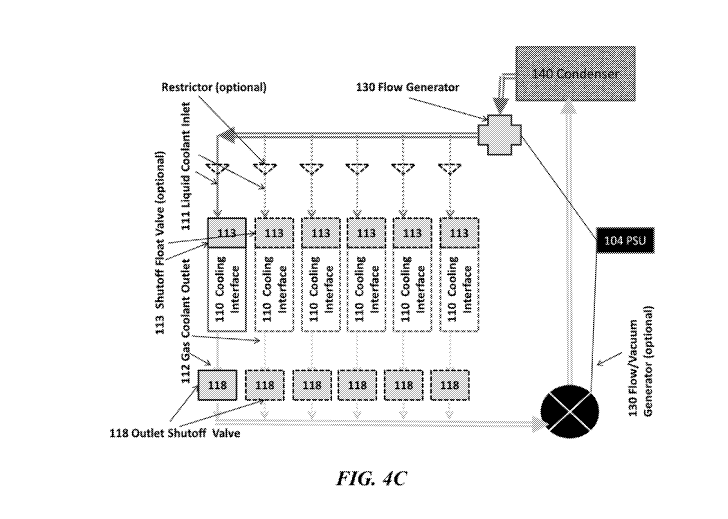
[0021] FIGs. 4A-4D schematically illustrate example cooling systems with one
or more cooling
interfaces; FIG. 4A schematically illustrates an example cooling system with a
single shut-off
valve regulating a single cooling interface; FIG. 4B schematically illustrates
a cooling system
with a single shut-off valve regulating multiple cooling interfaces; FIG. 4C
schematically
illustrates a cooling system with a single outlet shut-off valve regulating a
single cooling
interface; FIG. 4C schematically illustrates a cooling system with a single
outlet shut-off valve
regulating multiple cooling interfaces;
[0022] FIGs. 5A and 5B schematically illustrate example shut-off valves for
regulating the level
of liquid coolant present at the cooling interface; FIG. 5A schematically
illustrates an example
cooling interface with an inlet shut-off valve; FIG. 5B schematically
illustrates an example
cooling interface with an outlet shut-off valve and optional inlet shutoff
valve; and
[0023] FIG. 6 shows a computer control system that is programmed or otherwise
configured to
implement methods provided herein.
DETAILED DESCRIPTION
[0024] While various embodiments of the invention have been shown and
described herein, it
will be obvious to those skilled in the art that such embodiments are provided
by way of example
only. Numerous variations, changes, and substitutions may occur to those
skilled in the art
CA 03070836 2020-01-22
WO 2019/021273 PCT/IL2018/050809
without departing from the invention. It should be understood that various
alternatives to the
embodiments of the invention described herein may be employed.
[0025] As used herein, the term "condenser" generally refers to any device in
which a vapor
coolant is condensed to form a liquid coolant. The condenser may subject a
vapor to undergo a
phase change (or transition) to a liquid (i.e., condensation). For example,
the condenser may
condense a vapor coolant to a liquid coolant by altering the temperature of
the coolant or the
pressure of an environment containing the coolant. Heat removed from the
coolant may be stored
within the condenser or transmitted from the condenser, such as emitted from
the condenser
(e.g., using heat fins). Heat may be emitted to the surrounding free air
environment of may be
transferred to another heating, cooling, or thermal energy transfer device.
The transfer of thermal
energy may be achieved actively (e.g., by a fan attached to the condenser).
[0026] As used herein, the term "cooling interface" generally refers to any
device that may
absorb heat from a heat source (e.g., an electronic component). A cooling
interface may be in
direct contact with a heat source or indirect contact with a heat source
(e.g., via an interface,
mediator, or other heat conducting method, such as cooling pipes).
[0027] As used herein, the term "fluid" generally refers to a liquid or a gas.
A fluid may not
maintain a defined shape and may flow during an observable time frame to fill
a container in
which it is put. Thus, the fluid may have any suitable viscosity that permits
flow. If two or more
fluids are present, each fluid may be independently selected among essentially
any fluid (liquids,
gases, and the like).
[0028] As used herein, the term "coolant" generally refers to a substance,
such as a liquid or a
vapor (e.g., gas), that may be used to reduce, increase, or regulate the
temperature of a heat
source. The coolant can either maintain a phase or may undergo a phase
transition during
cooling, heating, or temperature regulation. In an example, the coolant may
undergo a phase
transition from a liquid phase to a gas phase to increase the cooling
efficiency of the coolant.
[0029] As used herein, the term "channel" generally refers to a feature on or
in a device or
system that may at least partially direct flow of a fluid. A channel may have
any cross-sectional
shape (e.g., circular, oval, triangular, irregular, square, rectangular,
etc.). A channel may be of
any suitable length. The channel may be straight, substantially straight, or
may contain one or
more bends, curves, or branches.
[0030] As used herein, the term "flow generator" generally refers to a
mechanism for directing
fluid through a channel. The flow generator may be a pump(s), a compressor(s),
an eductor or
6
CA 03070836 2020-01-22
WO 2019/021273 PCT/IL2018/050809
any other device that directs the flow of a fluid (e.g., liquid or vapor
coolant). The flow generator
may direct fluid flow in a pressurized, atmospheric, or vacuum system. In an
example, the flow
generator generates a vacuum in the system that facilitates fluid flow. The
vacuum may be at a
pressure of less than about 1 atmosphere (atm), or less than or equal to about
0.9 atm, 0.8 atm,
0.7 atm, 0.6 atm, 0.5 atm, 0.1 atm, 0.01 atm, 0.001 atm, or less.
[0031] The present disclosure provides systems and methods for heat exchange.
Systems and
methods of the present disclosure may be employed for use in various settings,
such as for use in
heat exchange with electronic systems (e.g. computer processors, computer
servers, data centers,
or network systems), energy storage systems (e.g., solid state batteries),
charging systems, three
dimensional (3D) printing systems, manufacturing systems, and wearable
devices.
Thermal regulation and transfer of thermal energy
[0032] The present disclosure provides thermal management systems for
regulating the
temperature of electronic systems, heat-generating components thereof, and
other heat generating
systems (e.g., energy storage devises, three dimensional printing devices,
etc.).
[0033] Thermal management or thermal regulation of electronic devices,
including servers,
central processing units (CPU), and graphics processing units (GPU), may
increase the
efficiency, longevity, and performance of such devices. Systems and methods
for thermal
regulation and transfer of thermal energy may include passive thermal
regulation and active
thermal regulation. Passive thermal regulation may include thermal regulation
that does not use
additional energy to provide thermal regulation. For example, passive thermal
regulation of a
device may include incorporating design features into the device that increase
dissipation of
thermal energy, such as heat sinks, heat spreaders, and heat pipes.
[0034] Active thermal regulation may include thermal regulation that uses
additional energy to
augment the thermal regulation process. Heat pumping thermal regulation may be
achieved by
material phase change, from liquid to gas, or by electro-cooling which may be
highly inefficient.
In some examples, the active thermal regulation may be provided by an external
device (e.g., a
fan). Methods of active thermal management may include forced air cooling,
forced liquid
cooling, solid-state heat pumps, electro-cooling and multiphase cooling.
Current active thermal
regulation systems and methods, such as the phase change cooling in
refrigeration and air-
conditioning systems, may employ forced condensation through pressurizing gas
to at least about
atm and evaporating the gas during pressure decrease to below about 3 atm.
Such systems,
however, may be limited by the high pressure working volume, size, rigidity,
and form factor of
the required pressure vessel.
7
CA 03070836 2020-01-22
WO 2019/021273 PCT/IL2018/050809
[0035] FIGs. 1A and 1B illustrate examples of single phase thermal regulation
systems using a
forced fluid. FIG. 1A shows an air-based thermal regulation system and FIG. 1B
shows a liquid-
based thermal regulation system. Single phase, force fluid (e.g., liquid or
gas) thermal regulation
systems may have limited cooling capabilities due to the ambient temperature
in which the
system operates. For example, an air-based single phase cooling system may not
be capable of
cooling a source of thermal energy below the ambient temperature due to the
rate of heat transfer
being proportional to the temperature gradient, as defined by Fourier's law.
Thermal regulation
systems may use cooled or chilled fluids to achieve cooling below ambient
temperatures. The
use of chilled fluids may inefficient as compared to a multiphase thermal
regulation system.
[0036] Multiphase thermal regulation systems may use latent heat from a phase
transition (e.g.,
from liquid to vapor) to cool below ambient temperatures. A multiphase thermal
management
system may be a two phase thermal regulation system. Multiphase thermal
regulation systems
may be high pressure systems or low pressure systems. High pressure systems
may be operated
at pressures above about 3 atmospheres (atm). High pressure systems may
include a gas or vapor
that undergoes forced condensation (e.g., using pressures greater than 10 atm)
followed by
evaporation via a pressure decrease (e.g., using pressures less than about 3
atm). The evaporation
process may occur adjacent to a source of thermal energy and the latent heat
used to convert the
fluid from a liquid to a vapor may draw thermal energy from the source of
thermal energy and,
therefore, cool the source of thermal energy. High pressure multiphase thermal
regulation
systems may have a large form factor, use ridged materials, and have robust
sealing mechanism
due to the high pressure (e.g., greater than 10 atm) of the system.
[0037] Low pressure thermal regulation system may use forced evaporation as an
alternative to
forced condensation. Vacuum (e.g., to achieve a pressure below 1 atm) may be
applied to a
liquid when the liquid is in contact with or in thermal communication with a
source of thermal
energy. The transfer of thermal energy from the source to the fluid may cause
the liquid to phase
transition to a vapor. The transition from liquid to vapor may draw thermal
energy from the
source of thermal energy and, therefore, cool the source of thermal energy.
The FIG. 2 shows an
example low pressure multiphase thermal regulation system comprising a closed
loop fluid flow
path. The example low pressure thermal regulation system comprises a cooling
interface 210.
The cooling interface 210 may be in contact with or in thermal communication
with a source of
thermal energy. A liquid coolant 250 may enter the cooling interface 210 and,
upon transfer of
thermal energy from the source of thermal energy, may undergo a phase change
to a vapor
coolant 220. The vapor coolant 220 may be directed from the cooling interface
210 to a
8
CA 03070836 2020-01-22
WO 2019/021273 PCT/IL2018/050809
condenser 230. The condenser may enable the vapor coolant 220 to emit heat and
phase
transition to the liquid coolant 250, thus regenerating the liquid coolant
250. The system may
include a vacuum or flow generator 240 to control and direct the flow of the
liquid coolant 250.
The vacuum or flow generator 240 may include a power supply 260 that powers
the flow
generator 240. The vacuum flow generator 240 may generate pressures less than
or equal to 2
atmosphere (atms), 1.5 atm, 1 atm, 0.8 atm, 0.6 atm, 0.4 atm, 0.2 atm, 0.1
atm, or less.
[0038] The rate of cooling of a low pressure thermal regulation system may be
dependent upon
the pressure of the system, the flow rate of the coolant, the boiling point of
the coolant, the
temperature gradient between the coolant and the source of thermal energy, and
the thermal
conductivity between the source of thermal energy and the coolant. FIG. 3
shows an example
plot of the boiling temperature of an example liquid coolant as a function of
percent vacuum
applied to a system. As the amount of vacuum is increased (e.g., the pressure
of the system is
reduced) the boiling point of the liquid coolant may decrease. As the amount
of vacuum is
decreased (e.g., the system becomes pressurized) the boiling point of the
liquid coolant may
increase. A liquid coolant that is in thermal communication with a heat source
may undergo a
temperature transition from the ambient temperature of the liquid coolant to
the boiling point of
the liquid coolant. As thermal energy continues to transfer to the liquid
coolant, the liquid
coolant may undergo a phase transition to a vapor coolant. The vapor coolant
may continue to
increase in temperature as thermal energy transfers from the heat source
(e.g., source of thermal
energy) to the vapor coolant. Thermal energy may be transferred from the
source to the coolant
during the changes in temperature of the coolant and the phase transition,
however, the transfer
of thermal energy may be more efficient during the phase transition than
during the temperature
change of the coolant. Thus, applying a vacuum to multiphase thermal
regulation system may
lower the boiling point of a liquid coolant and result in more efficient
cooling of a source of
thermal energy. Low pressure systems for thermal regulation are further
described in
PCT/IL2016/051384, PCT/IL2018/050280, and PCT/IL2018/050269, each of which is
entirely
incorporated herein by reference.
Systems for cooling a heat source
[0039] In an aspect, the present disclosure provides systems for cooling a
heat source and
maintaining the heat source within a temperature window. The systems may
comprise a closed
loop fluid flow path under vacuum. The closed loop fluid flow path may include
a first channel,
a second channel, a condenser, and at least one cooling interface. The first
channel (e.g., first
fluid flow path) may be configured to direct a liquid coolant. The second
channel (e.g., second
9
CA 03070836 2020-01-22
WO 2019/021273 PCT/IL2018/050809
fluid flow path) may be configured to direct a vapor coolant generated from
the liquid coolant.
The condenser may be configured to permit the vapor coolant to undergo a phase
transition to the
liquid coolant. The cooling interface may be in fluid communication with the
first channel and
the second channel. The cooling interface may include a coolant inlet, a heat
exchange unit, and
a coolant outlet. The first channel may direct the liquid coolant into the
coolant inlet of the
cooling interface. The coolant inlet direct and controls the flow of liquid
coolant from the coolant
inlet and towards the second channel. The coolant inlet may, or may not
comprise an inlet shut-
off valve. The heat exchange unit may permit heat to flow from a heat source
to the liquid
coolant. The heat may permit the liquid coolant to undergo a phase transition
to a vapor coolant.
The coolant outlet may permit the vapor coolant to flow from the heat exchange
unit to the
second channel. The coolant outlet may comprise an outlet shut-off valve. The
outlet shut-off
valve may permit or block the flow of vapor and/or liquid coolant from the
cooling interface to
the outlet channel. The system may absorb heat from a heat source by
vaporizing the liquid
coolant into a vapor coolant (e.g., through latent heat).
[0040] The system may be a high pressure (e.g., pressure greater than or equal
to 2 atm),
atmospheric pressure, or low pressure (e.g., pressure less than 2 atm) cooling
system. In an
example, the cooling system is a low pressure (e.g., vacuum) cooling system.
The pressure of the
cooling system may be constant throughout the system or may vary throughout
the system. For
example, the pressure may be greater in the condenser than in the channels or
at the cooling
interface. The pressure of the system may be less than or equal to about 5
atmospheres (atm), 4
atm, 3 atm, 2 atm, 1.5 atm, 1 atm, 0.8 atm, 0.6 atm, 0.4 atm, 0.2 atm, 0.1
atm, or less. The
pressure of the system may be between about 5 atm and 0.1 atm, 4 atm and 0.1
atm, 3 atm and
0.1 atm, 2 atm and 0.1 atm, 1.5 atm and 0.1 atm, 1 atm and 0.1 atm, 0.8 atm
and 0.1 atm, 0.6 atm
and 0.1 atm, 0.4 atm and 0.1 atm, or 0.2 atm and 0.1 atm. The pressure in the
condenser may be
greater than or equal to about 0.5 atm, 1 atm, 1.5 atm, 2 atm, 4 atm, 6 atm, 8
atm, 10 atm, or
greater. The pressure of the condenser may be between about 0.5 atm and 1 atm,
0.5 atm and 1.5
atm, 0.5 atm and 2 atm, 0.5 atm and 4 atm, 0.5 atm and 6 atm, 0.5 atm and 8
atm, or 0.5 atm and
atm. The pressure at the cooling interface may be less than or equal to about
(atm), 4 atm, 3
atm, 2 atm, 1.5 atm, 1 atm, 0.8 atm, 0.6 atm, 0.4 atm, 0.2 atm, 0.1 atm, or
less. The pressure at
the cooling interface may be between about 5 atm and 0.1 atm, 4 atm and 0.1
atm, 3 atm and 0.1
atm, 2 atm and 0.1 atm, 1.5 atm and 0.1 atm, 1 atm and 0.1 atm, 0.8 atm and
0.1 atm, 0.6 atm and
0.1 atm, 0.4 atm and 0.1 atm, or 0.2 atm and 0.1 atm. The difference in
pressure between the
cooling interface and other portions of the system (e.g., condenser, flow
generator, channels)
may be greater than or equal to about zero atm, 0.1 atm, 0.2 atm, 0.4 atm, 0.6
atm, 0.8 atm, 1
CA 03070836 2020-01-22
WO 2019/021273 PCT/IL2018/050809
atm, 1.5 atm, 2 atm, 4 atm, 6 atm, 8 atm, 10 atm, or more. The difference in
pressure between the
cooling interface and other portions of the system (e.g., condenser, flow
generator, channels)
may be less than or equal to about 10 atm, 8 atm, 6 atm, 4 atm, 2 atm, 1.5
atm, 1 atm, 0.8 atm,
0.6 atm, 0.4 atm, 0.2 atm, 0.1 atm, or less.
[0041] The outlet shut-off valve may prevent or block the flow of a portion
(e.g., may meter the
flow) or all of the coolant from the cooling interface to the outlet channel.
The reduced or
blocked flow may maintain the coolant within the cooling interface and may
increase the
pressure within the cooling interface and, thus, increase the boiling point of
the liquid coolant.
Increasing the pressure within the cooling interface may reduce or prevent the
coolant form
undergoing a phase transition from a liquid coolant to a vapor coolant. The
pressure within the
cooling interface may increase by greater than or equal to about 0.05 atm, 0.1
atm, 0.2 atm, 0.3
atm, 0.4 atm, 0.5 atm, 0.6 atm, 0.7 atm, 0.8 atm, 0.9 atm, 1 atm, 1.2 atm, 1.5
atm, 2 atm, 4 atm, 6
atm, 8 atm, 10 atm, or more. The outlet shut-off valve may maintain the
pressure within the
cooling interface within a pressure range by blocking or metering (e.g.,
reducing) the flow of
vapor and/or liquid coolant from the cooling interface. The outlet shut-off
valve may maintain
the pressure of the cooling interface between about 5 atm and 0.1 atm, 4 atm
and 0.1 atm, 3 atm
and 0.1 atm, 2 atm and 0.1 atm, 1.5 atm and 0.1 atm, 1 atm and 0.1 atm, 0.8
atm and 0.1 atm, 0.6
atm and 0.1 atm, 0.4 atm and 0.1 atm, or 0.2 atm and 0.1 atm.
[0042] The cooling system may cool or maintain a temperature of a heat source
by absorbing, or
not absorbing, heat from the heat source. Thermal energy may be absorbed by
the cooling
interface. The cooling interface may include one or more heat exchange units
or heat sinks that
take heat from the heat source and provide the heat to the liquid coolant. The
heat exchange units
may comprise a material with high thermal conductivity, such as, for example,
metals (e.g.,
copper, aluminum, iron, steel, etc.), non-metal conductors (e.g., graphite or
silicon), heat transfer
fluids, or any combination thereof. Non-limiting examples of heat transfer
fluids may include
halon replacement fluids (e.g., Novec fluids), R245fa, R123, R514a, other low
pressure coolants,
or any combination thereof. The heat exchange unit or heat sink may comprise a
chamber,
channels, or fins. The heat sink or heat exchange unit may generate a thin
layer of liquid coolant
in thermal communication with the heat source. The thin layer of coolant may
increase the
efficiency of cooling. The heat exchange unit may comprise a thin chamber. The
coolant may
flow parallel to a long dimension of the chamber. The chamber may have a
height (e.g., distance
perpendicular to the direction of fluid flow) of less than or equal to about
10 centimeters (cm), 8
cm, 6 cm, 5 cm, 4 cm, 3 cm, 2 cm, 1 cm, 0.5 cm, 0.25 cm, or less. The chamber
may have a
11
CA 03070836 2020-01-22
WO 2019/021273 PCT/IL2018/050809
height of greater than or equal to about 0.25 cm, 0.5 cm, 1 cm, 2 cm, 3 cm, 4
cm, 5 cm, 6 cm, 8
cm, 10 cm, or more. The chamber may have a volume of less than or equal to
about 4,000 cubic
centimeters (cm3), 3,500 cm3, 3,000 cm3, 2,500 cm3, 2,000 cm3, 1,500 cm3,
1,000 cm3, 750 cm3,
500 cm3, 250 cm3, 200 cm3, 150 cm3, 100 cm3, 75 cm3, 50 cm3, 25 cm3, 20 cm3,
15 cm3, 10 cm3,
8 cm3, 6 cm3, 4 cm3, 2 cm3, 1 cm3, 0.5 cm3, or less. The chamber may have a
volume of greater
than or equal to about 0.5 cm3, 1 cm3, 2 cm3, 4 cm3, 6 cm3, 8 cm3, 10 cm3, 15
cm3, 20 cm3, 25
cm3, 50 cm3, 75 cm3, 100 cm3, 150 cm3, 200 cm3, 250 cm3, 500 cm3, 750 cm3,
1,000 cm3, 1,500
cm3, 2,000 cm3, 2,500 cm3, 3,000 cm3, 3,500 cm3, 4,000 cm3, or more. The heat
sink or heat
exchange unit may have a cooling area of greater than or equal to about 0.5
squared centimeters
(cm2), 1 cm2, 2 cm2, 4 cm2, 6 cm2, 8 cm2, 10 cm2, 15 cm2, 20 cm2, 30 cm2, 40
cm2, 50 cm2, 75
cm2, 100 cm2, 150 cm2, 200 cm2, 300 cm2, 350 cm2, 400 cm2, or more. The heat
sink or heat
exchange unit may have a cooling area of less than or equal to 400 cm2, 350
cm2, 300 cm2, 250
cm2, 200 cm2, 150 cm2, 100 cm2, 75 cm2, 50 cm2, 40 cm2, 30 cm2, 20 cm2, 15
cm2, 10 cm2, 8
cm2, 6 cm2, 4 cm2, 2 cm2, 1 cm2, 0.5 cm2, or less.
[0043] The heat absorption via a cooling interface may be achieved through
liquid coolant
vaporization. Vaporization may be achieved by applying vacuum onto the coolant
or cooling
agent within the cooling interface(s). Alternatively, or in addition to,
vaporization may be
achieved by allowing the coolant to evaporate and evacuating the gaseous
coolant. The
evaporated coolant may be removed or taken away from the cooling interface and
directed to the
condenser. The condenser may condense the vapor coolant to form a liquid
coolant. The
absorbed heat may be emitted from the condenser to the surrounding environment
(e.g.,
surrounding air) or to another device. The liquid coolant may flow from the
condenser to the
cooling interface. Alternatively, or in addition to, the liquid coolant may
flow from the condenser
to a flow generator or other vacuum component of the cooling system.
[0044] FIGs. 4A and 4B schematically illustrate an example cooling systems
with one or more
cooling interfaces 110. The cooling system 100 may include one or more fluid
flow channels and
multiple cooling interfaces 113. The cooling interfaces may include a liquid
coolant inlet 111, an
inlet shut-off valve 113 to control the flow of liquid coolant into the
cooling interface, and a gas
or vapor coolant outlet 112. The system may further comprise a condenser 140,
one or more flow
generators 130, and a power supply 104 coupled to the flow generators. The
liquid coolant may
flow from the condenser 140, through a channel, and to the liquid coolant
inlet 111. The inlet
shut-off valve 113 may block the liquid coolant from entering the cooling
interface 110 or may
permit the liquid coolant to enter the cooling interface 110. The cooling
interface 110 may be in
12
CA 03070836 2020-01-22
WO 2019/021273 PCT/IL2018/050809
contact with a heat source and heat may be transferred from the heat source to
the liquid coolant.
The liquid coolant may be vaporized and may exit the cooling interface through
the gas coolant
outlet 112 to be directed to the condenser. The system 100 may include
multiple cooling
interfaces 110 and multiple inlet shut-off valves 113. Each inlet shut-off
valve may be in fluid
communication with a single cooling interface 110 as shown in FIG. 4A.
Alternatively, or in
addition to, each inlet shut-off valve may be in fluid communication with
multiple cooling
interfaces 110 as shown in FIG. 4B.
[0045] FIGs. 4C and 4D schematically illustrate an example cooling system 100
with one or
more cooling interfaces 110 in fluid communication with one or more coolant
outlets 112. The
one or more coolant outlets may include one or more outlet shut-off valves
118. The outlet shut-
off valve 118 may aid in controlling the amount of coolant in the cooling
interface 110 and the
pressure of the cooling interface 110, thereby maintaining the temperature of
the heat source.
The cooling system 100 may comprise a first channel, a second channel, a
condenser 140, and
one or more cooling interfaces 110. The first channel may be configured to
direct a liquid
coolant to the cooling interface 110. The first channel may be in fluid
communication with an
inlet shut-off valve 113. Alternatively, or in addition to, the first channel
may not include an
inlet shut-off valve 113. The second channel may be configured to direct a
vapor coolant
generated from the liquid coolant to the condenser 140. The condenser 140 may
be configured to
permit the vapor coolant to undergo phase transition to the liquid coolant.
The at least one
cooling interface may be in fluid communication with the first channel and the
second channel.
At least one cooling interface may comprise a coolant inlet 111, at least one
heat exchange unit,
and the coolant outlet 112 comprise with an outlet shut-off valve 118. The
coolant inlet 111 may
comprise an inlet shut-off valve 113 for directing the liquid coolant from the
first channel
towards the second channel. The at least one heat exchange unit may permit
heat to flow from a
source of thermal energy to the liquid coolant from the coolant inlet 111. At
least one heat
exchange unit may permit the liquid coolant to undergo phase transition to the
vapor coolant.
The coolant outlet 112 comprising the outlet shut-off valve 118 may permit the
vapor coolant to
controllably flow from the at least one heat exchange unit to the second
channel. The system 100
may include multiple coolant outlets 112 and multiple outlet shut-off valves
118. Each shut-off
valve may be in fluid communication with a single cooling interface 110 as
shown in FIG. 4C.
Alternatively, or in addition to, each outlet shut-off valve 118 may be in
fluid communication
with multiple cooling interfaces 110 as shown in FIG. 4D. In an example, a
portion of the
cooling interfaces 110 are in fluid communication with a single outlet shut-
off valve 118 and,
optionally a single inlet shut-off valve 113. In another example, individual
cooling interfaces
13
CA 03070836 2020-01-22
WO 2019/021273 PCT/IL2018/050809
110 are in fluid communication with individual outlet 118 and, optionally,
inlet 113 shut-off
valves. A system may include a mixture of cooling interfaces associated with
individual inlet
and/or outlet shut-off valves and multiple cooling interfaces associated with
a single inlet and/or
outlet shut-off valves.
[0046] The cooling system may further include a flow generator. The flow
generator may be a
pump, compressor, educator, or any other device designed to direct fluid flow.
The cooling
system may include at least 1, 2, 3, 4, 5, or more flow generators. The flow
generators may be
the same type of flow generator. Alternatively, the system may not include a
flow generator. The
flow generator may be controlled by a control unit that can activate the flow
generator when a
temperature threshold is reached or when faster heat removal is required. The
flow generator
may permit the system to operate at a low pressure (e.g., less than 2 atm).
Such low pressure
system may operate, for example, at a pressure that is less than or equal to
about 2 atm, 1.5 atm,
1 atm, 0.5 atm, 0.1 atm, or less (e.g., under vacuum). For example, the flow
generator may
generate a vacuum that directs flow of the coolant in its liquid form and/or
its gaseous form. The
flow generator may direct fluid at a volumetric flow rate of greater than or
equal to about 0.5
liters per hour (L/h), 1 L/h, 2 L/h, 5 L/h, 10 L/h, 20 L/h, 30 L/h, 40 L/h, 50
L/h, 100 L/h, 200
L/h, 300 L/h, 400 L/h, 500 L/h, 1,000 L/h, 2,000 L/h, 3,000 L/h, 4,000 L/h,
5,000 L/h, 10,000
L/h, 20,000 L/h, 30,000 L/h, 40,000 L/h, or greater. The flow generator may
direct fluid at a
volumetric flow rate of less than or equal to about 40,000 L/h, 30,000 L/h,
20,000 L/h, 10,000
L/h, 5,000 L/h, 4,000 L/h, 3,000 L/h, 2,000 L/h, 1,000 L/h, 500 L/h, 400 L/h,
300 L/h, 200 L/h,
100 L/h, 50 L/h, 40 L/h, 30 L/h, 20 L/h, 10 L/h, 5 L/h, 2 L/h, 1 L/h, 0.5 L/h,
or less.
[0047] The flow generator may direct fluid flow from the condenser, through a
channel to the
cooling interface, and from the cooling interface back to the condenser. The
system may include
a 2, 3, 4, 5, 6, 8, 10, or more channels. In an example, the system includes a
first channel and a
second channel. The first channel may direct the flow of liquid coolant and
the second channel
may direct the flow of vapor coolant. The channels may be flexible or ridged.
The channels may
be formed of thermally insulating materials (e.g., plastics). The first and
second channel may be
formed of the same materials or may be formed of different materials. The
channels may have a
cross-sectional area that is constant or that varies. The first and the second
channel may have the
same cross-sectional area or may have different cross-sectional areas. For
example, the cross-
sectional area of the first channel (e.g., the channel directing the liquid
coolant) may be smaller
than the cross-sectional area of the second channel (e.g., the channel
directing the vapor coolant).
14
CA 03070836 2020-01-22
WO 2019/021273 PCT/IL2018/050809
[0048] The system may further comprise a plurality of outlet shut-off valves.
The outlet shut-off
valves may be disposed between the heat exchange unit of the cooling interface
and the outlet
channel. Alternatively, or in addition two, the outlet shut-off valves may be
integrated with the
outlet channel and/or or the cooling interface. In an example, the system
includes multiple heat
exchange units and each outlet shut-off valve controls the flow of fluid from
a single heat
exchange unit to the outlet channel. In another example, the one outlet shut-
off valve controls
fluid flow from more than one heat exchange units. The outlet shut-off valve
may be a metered
valve (e.g., controls the flow rate of the fluid) or may be a discrete valve
(e.g., valve comprising
an open state and a closed state). The outlet shut-off valve may be designed
to allow vapor,
liquid, and or vapor and liquid coolant to enter each associated outlet
channel which is in fluid
communication therewith, while preventing backflow of the vapor and/or liquid
coolant.
[0049] The system may further comprise one or more inlet shut-off valves. In
an example, the
system comprises no inlet shut-off valves. In another example, the system
comprises multiple
inlet shut-off valves. The one or more inlet shut-off valves may be disposed
between the first
channel and the heat exchange unit of the cooling interface. In an example,
the system includes
multiple heat exchange units and each inlet shut-off valve controls the flow
of fluid to a single
heat exchange unit. In another example, one inlet shut-off valve controls
fluid flow to more than
one heat exchange units. The inlet shut-off valve may be integrated with the
inlet channel and/or
the cooling interface. The inlet shut-off valve may be a metered valve (e.g.,
controls the flow
rate of the fluid) or may be a discrete valve (e.g., valve comprising an open
state and a closed
state). The inlet shut-off valve may be designed to allow liquid coolant to
enter each associated
cooling interface which is in fluid communication therewith, while preventing
backflow of the
liquid coolant as well as of the generated gaseous or vapor coolant.
[0050] The outlet and/or inlet shut-off valve may be a mechanical or electric
valve. The outlet
and/or inlet shut-off valve may be controlled by a control unit or may be
physically controlled
(e.g., by liquid coolant level). In an example, the outlet and/or inlet shut-
off valve is a float valve
designed to prevent liquid coolant from entering the associated cooling
interface when the liquid
coolant within the cooling interface unit reaches a predefined level/amount.
In another example,
the system comprises an outlet shut-off valve that is not a float valve and an
inlet shut-off valve
that is a float valve. For example, when the liquid level is below a threshold
volume or level, the
inlet shut-off float valve may be in an open position and allow liquid coolant
to flow into the
cooling interface. When the liquid level reaches the threshold volume or level
the float valve
may be in a closed interface and prevent liquid coolant from flowing into the
cooling interface.
CA 03070836 2020-01-22
WO 2019/021273 PCT/IL2018/050809
Using a float valve may reduce the use of a flow generator to continuously
flow the coolant
through the cooling system which may reduce maintenance costs and redundant
flow generators.
[0051] A float shut-off valve may increase the efficiency of the cooling
system because liquid
coolant enters the cooling interface in which the liquid coolant level has
been dropped or reduced
and not a cooling interface in which the liquid coolant level is above a
threshold. The reduction
in the liquid coolant volume or level may be indicative of on-going heat
removal from the heat
source being and which the cooling interface is thermally connected to or
associated-with. Thus,
the efficiency of the system may be increased because coolant is being
delivered to the cooling
interfaces undergoing heat removal and not to the cooling interfaces where
heat is not being
removed. Moreover, the rate and speed of liquid coolant entering each cooling
interface may be
controlled by the rate of evaporation, which may be equivalent to the amount
of heat to be
removed (e.g., the hotter the heat source, the faster the coolant within a
specific cooling interface
evaporates, and thus the rate at which the liquid coolant enters the specific
cooling interface is
faster, and vice-versa). This permits autonomous or on demand temperature
control of the heat
source to be cooled. A float valve may be in fluid communication with a single
heat exchange
unit or a float valve may be in fluid communication with multiple heat
exchange units.
[0052] A cooling system comprising an outlet and/or inlet shut-off valve may
be advantageous
because the liquid coolant does not flow continuously and/or circularly (e.g.,
does not flow into
and out of each cooling interface). The liquid coolant may enter each cooling
interface of the
system and vapor or gaseous coolant may exit or leave the cooling interface.
The inlet shut-off
valve may prevent liquid coolant, vapor coolant, or both liquid and vapor
coolant from entering
the first channel. The outlet shut-off valve may prevent liquid coolant, vapor
coolant, or both
liquid and vapor coolant from entering the second channel. In an example, the
outlet and/or inlet
shut-off valve permits the cooling system to be autonomous (e.g., to not use a
control system to
control the amount and speed of liquid coolant that is pumped through the
system and into each
cooling interface or the speed of removal of the vapor or gaseous coolant from
the cooling
interface).
[0053] Alternatively, or in addition to, the cooling system may further
comprises a control unit
for controlling the amount and speed of liquid coolant pumped through the
system and/or into
each cooling interface. The control unit may control the removal speed of
coolant vapors from
the cooling interface and/or the flow of ambient air through cooling fins of
the condenser (e.g.,
fan speed). In an example, the liquid coolant flow rate and/or the gaseous
coolant flow rate is
controlled by at least one pressure regulator associated with flow generator.
The control unit may
16
CA 03070836 2020-01-22
WO 2019/021273 PCT/IL2018/050809
be in communication with the inlet shut-off valve, outlet shut-off valve, or
both the inlet and
outlet shut-off valve. The control unit may signal the inlet shut-off valve to
open with the
temperature of the cooling interface or object to be cooled rises above an
upper temperature limit
or threshold. The control unit may signal the outlet shut-off valve to close
when the temperature
of the cooling interface or object to be cooled falls below a lower
temperature limit or threshold.
[0054] The cooling interface may contain a threshold or residual amount of
liquid coolant and
either the inlet and/or the outlet shut-off valve may prevent liquid coolant
from entering or
leaving the cooling interface once the threshold level or amount has been
reached. The inlet shut-
off valve may permit the liquid coolant to enter the cooling interface once
the coolant level has
dropped below the threshold level. Alternatively, or in addition two, the
outlet shut-off valve
may prevent vapor and/or liquid coolant from flowing from the cooling
interface once the
coolant level has dropped below the threshold level. The level of the coolant
in the cooling
interface may be reduced due to evaporation of the liquid coolant. Evaporation
of the liquid
coolant may be due to the transfer of heat from the heat source to the liquid
coolant.
[0055] The outlet and/or inlet shut-off valve may be any valve that is
suitable for permitting one-
directional flow, which directs coolant to flow into cooling interface(s) or
to the outlet channel,
while preventing backflow of the liquid or vapor coolant. The outlet and/or
inlet shut-off valve
may be a mechanical or electric float valve.
[0056] Example shut-off valves are illustrated in FIGs. 5A and 5B. FIG. 5A
illustrates an
example cooling interface 110 with an inlet shut-off valve. The valve may be a
float valve or
other type of valve. FIG. 5B illustrates and example of a cooling interface
110 with an outlet
shut-off valve 118 and inlet shut-off valve 113. The inlet shut-off valve 113
may be an optional
component of the system. The inlet shut-off valve 113 may permit control of
the level of the
coolant within the cooling interface 110. For example, a system may comprise a
liquid coolant
inlet 111 that provides liquid coolant to the cooling interface 110. The
system may additionally
comprise a gas coolant outlet 112 that removes gas coolant from the cooling
interface 110. The
gas coolant outlet may further comprise an outlet shut-off valve 118. The
outlet shut-off valve
118 may permit the regulation of the pressure of the cooling interface and,
therefore, may permit
maintaining the cooling interface 110 within a window or range of
temperatures. The inlet shut-
off valve 113 may be disposed adjacent to the liquid coolant inlet 111 of the
cooling interface
110. The shut-off float valve may include a float that is disposed at the
interface between the
liquid coolant and the vapor coolant. The shut-off float valve may indicate
the liquid coolant
level within the cooling interface. A decrease in the liquid coolant level may
cause the position
17
CA 03070836 2020-01-22
WO 2019/021273 PCT/IL2018/050809
of the float to decreases the valve to open. An increase in the liquid coolant
level may cause the
position of the float to increase and the valve to close.
[0057] An inlet and an outlet shut-off valve may be the same type of valve or
may be a different
valve. For example, the inlet valve may be a float valve and the outlet shut-
off valve may be a
pneumatic, electric, or mechanical valve. The outlet shut-off valve may be a
two stage valve
with an open and/or close setting or a multi-stage valve that may limit or
restrict (e.g., regulate)
outlet gas flow from the one or more cooling interfaces. The inlet, outlet, or
both the inlet and
outlet shut-off valves may be controlled using a solenoid for opening and
closing the valve. The
outlet and/or inlet shut-off valve may include additional components, such as
springs,
diaphragms, pneumatic components, or additional fluids to permit the valve to
block, partially
block, or meter flow of the liquid coolant and/or vapor coolant.
[0058] The inlet shut-off float valve may be a mechanical shut-off valve. The
specific gravity of
the float portion of the valve may be less than the specific gravity of the
coolant. Accordingly,
when no external forces are applied other than the force of the coolant level
rising, the inlet shut-
off valve may be lifted and block or close the coolant flow path into the
cooling interface. As the
coolant evaporates, the liquid level may decrease and the valve may lower and
open or unblock
the coolant flow path into the cooling interface. Once the liquid coolant
level within the cooling
interface begins to drop, the valve may automatically open to allow liquid
coolant to enter the
cooling interface. The flow rate of the liquid coolant into the cooling
interface may directly
correlate to the amount of gaseous or vapor coolant exiting the cooling
interface. The amount of
vapor coolant generated may be a direct effect of the heat generated by the
heat source to be
cooled. Using an inlet shut-off float valve may eliminate the use of
sophisticated and complex
controlling and adjusting mechanism(s) and monitoring of the cooling process.
In an example,
the forces induced by the specific gravity differences (e.g., between the
valve specific gravity
and the coolant specific gravity), is high enough to block, partially block,
or meter the flow of
liquid coolant to or through the liquid coolant inlet. The inlet shut-off
valve may include
additional components, such as springs, diaphragms, pneumatic components, or
additional fluids
to permit the valve to block, partially block, or meter flow of the liquid
coolant.
[0059] The cooling system may have a single cooling interface or multiple
cooling interfaces.
The cooling system may have at least 2, 3, 4, 6, 8, 10, 20, 40, 60, 80, 100,
or more cooling
interfaces. The cooling system may include cooling interfaces connected in a
parallel or series
configuration. The cooling system may include at least one line or set of 2,
3, 4, 5, 6, 7, 8, 9, 10
or more cooling interface connected in a series configuration. Alternatively,
or in addition to, the
18
CA 03070836 2020-01-22
WO 2019/021273 PCT/IL2018/050809
cooling system may have at least one line or set of 2, 3, 4, 5, 6, 7, 8, 9, 10
or more cooling
interface connected in parallel. In an example, the cooling system comprises
at least one line or
set of 2, 3, 4, 5, 6, 7, 8, 9, 10 or more cooling interface connected both in
series and in parallel.
The cooling interfaces of the system may be grouped such that a single outlet
shut-off valve
controls the flow of coolant from the group of cooling interfaces. The cooling
system may have
multiple groups of cooling interfaces, each in fluid communication with a
single outlet shut-off
valve. A group of cooling interfaces may include at least 2, 3, 4, 5, 6, 7, 8,
9, 10, or more cooling
interfaces. A cooling system may include at least 2, 3, 4, 5, 6, 7, 8, 9, 10,
20, 30, 40, 50, or more
groups of cooling interfaces.
[0060] The cooling system may include one or more coolants or cooling agents.
The coolant
may be a refrigerant, a dielectric fluid, or any fluid with a high latent heat
of evaporation. The
liquid coolant may be non-corrosive and may be compatible with electronic
components. The
liquid coolant may also be non-toxic and non-flammable. The coolant may
comprise aromatic,
silicate-ester, aliphatic, silicone, or fluorocarbon compounds. The coolant
may include alcohol,
water, glycol, a salt solution, or any combination thereof. The cooling system
may be provided
empty (e.g., without any coolant) and coolant may be added to the system after
installation of the
cooling system. The coolant or cooling agent may vaporize at less than or
equal to about 1 atm at
a low temperature. The coolant may vaporize at a pressure of less than or
equal to about 1 atm
and a temperature between about 0 C to about 40 C, about 0 C to about 30 C,
about 0 C to
about 20 C, about 0 C to about 10 C, about 5 C to about 25 C, about 10 C to
about 25 C, about
15 C to about 25 C, or from about 5 C to about 20 C. The coolant or cooling
agent may
vaporize at 25 C at a pressure of from about 0 atm to about 1 atm, from about
zero atm to about
0.8 atm, from about zero atm to about 0.5 atm, from about zero atm to about
0.3 atm, or from
about zero atm to about 0.1 atm.
[0061] The cooling system may further comprise a power source, such as power
supply or a
battery. The system may be connected directly to the main power grid.
[0062] The cooling system may directly absorb heat from at least one heat
source by a direct or
indirect contact of the cooling interface with the heat source (e.g.,
electronic device). Utilizing
latent heat (i.e. liquid vaporization), the cooling system may cool the heat
source. Vaporization
may be permitted by applying vacuum to the coolant or cooling agent. The
vaporized coolant
may be transferred to the condenser to be condensed to form a liquid coolant.
The condenser
may emit the heat absorbed from the heat source into the environment, to
another device, and/or
to a heat absorbing material. The liquid coolant may then be directed to the
vacuum applied
19
CA 03070836 2020-01-22
WO 2019/021273 PCT/IL2018/050809
component of the apparatus (e.g., the cooling interface or an expansion
container). In an
example, the cooling interfaces are in direct contact with the heat source.
The heat source may be
cooled by placing the cooling interfaces in direct or indirect contact (e.g.,
through a heat
conductor) with the heat source.
[0063] The cooling system may be used to cool any type of heat source. For
example, the
cooling system may be used to cool a server room or farm, central processing
unit (CPU),
graphics processing unit (GPU), or any other electronic component which
generates heat (e.g., a
computer or any other electronic device).
[0064] The cooling system may include one or more a controllers for
controlling the operation of
the system. The controller may control flow of the coolant, rate of
condensation of the coolant,
temperature thresholds for providing coolant, or any combination thereof. The
cooling system
may comprise one or more orifices or expansion chambers. The orifice or
expansion chamber
may be in fluid communication with the channels (e.g., the first or second
channel). The orifices
or expansion chambers may be in fluid communication with the cooling
interface. The orifices or
expansion chambers may decrease the pressure within the cooling interface. The
expansion
chamber or container may accumulate liquid coolant prior to providing the
liquid coolant to the
cooling interface. The cooling system may include one or more splitters that
split the fluid flow
paths (e.g., coolant and vacuum) between parallel cooling interfaces. The
cooling system may
include coolant pipes in which the coolant flows. The coolant pipes may be
flexible and made of
any suitable material, such as plastic, rubber, silicone, polyurethane, or
metal.
[0065] The cooling system may include power wires or communication wires. The
power wires
may provide power to the cooling system or heat source. The communication
wires may be in
communication with the controller and may permit the controller to control the
cooling system.
The cooling system may include a user interface for displaying the temperature
at the cooling
interface and/or the surroundings. The user interface may be any screen, such
as a computer
screen, a tablet or a smart phone, or a screen attached to or associated with
the cooling system or
the heat source. The cooling system may include one or more thermocouples or
temperature
sensors. The thermocouples may be in communication with the controller and may
permit
automatic activation of the cooling system when the temperature reaches an
upper or a lower
temperature threshold. The upper temperature threshold may be greater than or
equal to about
C, 15 C, 20 C, 25 C, 30 C, 35 C, 40 C, 45 C, 50 C, 60 C, 70 C, 80 C, 90 C,
100 C,
110 C, 120 C, or greater. The lower temperature threshold may be less than or
equal to about
120 C, 110 C, 100 C, 90 C, 80 C, 70 C, 60 C, 50 C, 45 C, 40 C, 35 C, 30 C, 25
C, 20 C,
CA 03070836 2020-01-22
WO 2019/021273 PCT/IL2018/050809
15 C, 10 C, or less. The thermocouples may be in communication with the
controller and may
permit automatic activation of the cooling system when the temperature is
outside of a
temperature range or temperature window. The temperature range or window may
be between
about 5 C and 10 C, 5 C and 20 C, 5 C and 30 C, 5 C and 40 C,5 C and 50
C, 5 C and
60 C, 5 C and 70 C, 5 C and 90 C, 5 C and 90 C, 5 C and 100 C, 5 C and 110
C, 5 C
and 120 C, 10 C and 20 C, 10 C and 30 C, 10 C and 40 C, 10 C and 50 C, 10 C
and 60 C,
C and 70 C, 10 C and 80 C, 10 C and 90 C, 10 C and 100 C, 10 C and 120 C, 20
C and
30 C, 20 C and 40 C, 20 C and 50 C, 20 C and 60 C, 20 C and 70 C, 20 C and 80
C, 20 C
and 90 C, 20 C and 100 C, 20 C and 120 C, 30 C and 40 C, 30 C and 50 C, 30 C
and 60 C,
30 C and 70 C, 30 C and 80 C, 30 C and 90 C, 30 C and 100 C, 30 C and 110 C,
30 C and
120 C, 40 C and 50 C, 40 C and 60 C, 40 C and 70 C, 40 C and 80 C, 40 C and 90
C, 40 C
and 100 C, 40 C and 110 C, 40 C and 120 C, 50 C and 60 C, 50 C and 70 C, 50 C
and 80 C,
50 C and 90 C, 50 C and 100 C, 50 C and 110 C, 50 C and 120 C, 60 C and 70 C,
60 C and
80 C, 60 C and 90 C, 60 C and 100 C, 60 C and 110 C, 60 C and 120 C, 70 C and
80 C,
70 C and 90 C, 70 C and 100 C, 70 C and 110 C, 70 C and 120 C, 80 C and 90 C,
80 C and
100 C, 80 C and 110 C, 80 C and 120 C, 90 C and 100 C, 90 C and 110 C, 90 C
and 120 C,
100 C and 110 C, 100 C and 120 C, or 110 C and 120 C.
[0066] The cooling system may include a transmitter for transmitting date
(e.g., temperature or
coolant flow rate) to a remote computer or smart phone, either constantly or
periodically. The
cooling system may include a computer processor and memory. The computer
processor and
memory may control the cooling system and store data from the cooling system
and heat source.
[0067] The cooling system may further comprise pump or pumps that may assist
in flowing the
coolant and/or coolant vapors in the system, as well as a filter or filtration
subsystem that allows
filtration of the coolant and thus prevent possible clogging of the system.
[0068] The cooling system may comprise at least one sensor. The sensor may
permit the cooling
system to sense that the temperature of either the heat source or the
surroundings has exceeded
predetermined temperature (e.g., a temperature at which the heat source may be
damaged or
become inoperable). The sensor may send an alert, turn the cooling system on,
or increase the
activity of the cooling system by increasing work load, activate additional
parallel cooling
interfaces, and/or execute an emergency shutdown of the heat source or the
entire electronic
system comprising the heat source.
[0069] The cooling system may comprise a thermostat. The thermostat may permit
the cooling
system to activate and cool the heat source when the threshold temperature of
the heat source or
21
CA 03070836 2020-01-22
WO 2019/021273 PCT/IL2018/050809
temperature of the surroundings has been reached. Operating the cooling system
when the
threshold temperature has been reached and not when the threshold temperature
has not been
reached may increase efficiency of the system and reduce resource use (e.g.,
power).
[0070] The system may be controlled by a control unit or may be self-
regulating. Such self-
regulation may be employed using an outlet and/or inlet shut-off valve, such
as a float valve or
pressure relief valve. Such self-regulation may be employed in the absence of
a sensor that
detects fluid level or fluid volume. The system may further comprise a
pressure regulator that
regulates the pressure of the cooling interface, condenser, channels, or any
combination thereof.
The pressure regulator may be in fluid communication with at least one of the
first channel, the
second channel, the cooling interface, the condenser, the flow generator, or
any combination
thereof. In an example, the system comprises multiple pressure regulators and
each pressure
regulator may be in fluid communication with multiple components of the
system. The pressure
regulate may control the flow rate of the liquid coolant or the vapor coolant.
Methods for cooling a heat source
[0071] In another aspect, the present disclosure provides methods for cooling
a heat source. The
method may include providing a cooling system comprising at least one cooling
interface in fluid
communication with a first channel, a second channel, and a condenser. The
cooling interface
may include a coolant inlet, a heat exchange unit, and a coolant outlet. The
coolant outlet may
comprise an outlet shut-off valve. The cooling system may further comprise an
inlet shut-off
valve. The method may include directing a liquid coolant from the first
channel of the cooling
system to the cooling interface using heat from the at least one heat exchange
unit to subject the
liquid coolant to a phase transition to form a vapor coolant, directing the
vapor coolant from the
cooling interface through the second channel to the condenser, and subjecting
the vapor coolant
to a second phase transition to form the liquid coolant. The condensed liquid
coolant may be
directed back to the first channel. The liquid coolant may accumulate at the
cooling interface and
may evaporate to form a vapor coolant.
[0072] The cooling system may further include a flow generator and the method
may include
activating the flow generator. The flow generator may be a pump, compressor,
educator, or any
other device designed to direct fluid flow. The cooling system may include at
least 1, 2, 3, 4, 5,
or more flow generators. The flow generators may be the same type of flow
generator.
Alternatively, the system may not include a flow generator. The flow generator
may be
controlled by a control unit that can activate the flow generator when a
temperature threshold is
reached or when faster heat removal is required. The flow generator may be
activated when a
22
CA 03070836 2020-01-22
WO 2019/021273 PCT/IL2018/050809
threshold temperature of the heat source or environment surrounding the heat
source is reached.
The flow generator may permit the system of operate a low pressure (e.g., less
than 2 atm). For
example, the flow generator may generate a vacuum that directs the flow of the
coolant in its
liquid form and/or its gaseous form. The flow generator may direct fluid at a
volumetric flow
rate of greater than or equal to about 0.5 liters per hour (L/h), 1 L/h, 2
L/h, 5 L/h, 10 L/h, 20 L/h,
30 L/h, 40 L/h, 50 L/h, 100 L/h, 200 L/h, 300 L/h, 400 L/h, 500 L/h, 1,000
L/h, 2,000 L/h, 3,000
L/h, 4,000 L/h, 5,000 L/h, 10,000 L/h, 20,000 L/h, 30,000 L/h, 40,000 L/h, or
greater. The flow
generator may direct fluid at a volumetric flow rate of less than or equal to
about 40,000 L/h,
30,000 L/h, 20,000 L/h, 10,000 L/h, 5,000 L/h, 4,000 L/h, 3,000 L/h, 2,000
L/h, 1,000 L/h, 500
L/h, 400 L/h, 300 L/h, 200 L/h, 100 L/h, 50 L/h, 40 L/h, 30 L/h, 20 L/h, 10
L/h, 5 L/h, 2 L/h, 1
L/h, 0.5 L/h, or less. The method may comprise activating a flow generator to
flow the coolant
within the system.
[0073] The activation of the cooling system may be automatic (e.g., self-
regulating) when a
threshold temperature is reached or may be controlled by a controller. The
temperature of the
cooling system and heat source may be monitored or the temperatures may not be
monitored.
The coolant flow rate of the system may increase or decrease as the
temperature of the heat
sources increases and decreases, respectively. The coolant flow rate may be
self-regulated or
controlled by the flow generator.
[0074] The method may include monitoring the temperature of the heat source,
the environment
surrounding the heat source, or the cooling interface. The temperature may be
monitored by one
or more thermocouples. The thermocouples may be in communication with the
controller and
may permit automatic activation of the cooling system when the temperature
reaches an upper
temperature threshold. The upper temperature threshold may be greater than or
equal to about
C, 15 C, 20 C, 25 C, 30 C, 35 C, 40 C, 45 C, 50 C, 60 C, 70 C, 80 C, 90 C,
100 C,
110 C, 120 C, or greater. The thermocouple may signal the controller to stop
directing coolant
away from the cooling interface when the temperature is below a lower limit of
the temperature
window or range. The lower limit of the temperature window or range may be
less than or equal
to 120 C, 110 C, 100 C, 90 C, 80 C, 70 C, 60 C, 50 C, 45 C, 40 C, 35 C, 30 C,
25 C, 20 C,
C, 10 C, or less. The thermocouples may be in communication with the
controller and may
permit automatic activation of the cooling system when the temperature is
outside of a
temperature range or temperature window. The temperature range or window may
be between
about 5 C and 10 C, 5 C and 20 C, 5 C and 30 C, 5 C and 40 C, 5 C and
50 C, 5 C and
60 C, 5 C and 70 C, 5 C and 90 C, 5 C and 90 C, 5 C and 100 C, 5 C and 110
C, 5 C
23
CA 03070836 2020-01-22
WO 2019/021273 PCT/IL2018/050809
and 120 C, 10 C and 20 C, 10 C and 30 C, 10 C and 40 C, 10 C and 50 C, 10 C
and 60 C,
C and 70 C, 10 C and 80 C, 10 C and 90 C, 10 C and 100 C, 10 C and 120 C, 20
C and
30 C, 20 C and 40 C, 20 C and 50 C, 20 C and 60 C, 20 C and 70 C, 20 C and 80
C, 20 C
and 90 C, 20 C and 100 C, 20 C and 120 C, 30 C and 40 C, 30 C and 50 C, 30 C
and 60 C,
30 C and 70 C, 30 C and 80 C, 30 C and 90 C, 30 C and 100 C, 30 C and 110 C,
30 C and
120 C, 40 C and 50 C, 40 C and 60 C, 40 C and 70 C, 40 C and 80 C, 40 C and 90
C, 40 C
and 100 C, 40 C and 110 C, 40 C and 120 C, 50 C and 60 C, 50 C and 70 C, 50 C
and 80 C,
50 C and 90 C, 50 C and 100 C, 50 C and 110 C, 50 C and 120 C, 60 C and 70 C,
60 C and
80 C, 60 C and 90 C, 60 C and 100 C, 60 C and 110 C, 60 C and 120 C, 70 C and
80 C,
70 C and 90 C, 70 C and 100 C, 70 C and 110 C, 70 C and 120 C, 80 C and 90 C,
80 C and
100 C, 80 C and 110 C, 80 C and 120 C, 90 C and 100 C, 90 C and 110 C, 90 C
and 120 C,
100 C and 110 C, 100 C and 120 C, or 110 C and 120 C. In an example, the
temperature
window may be between.
[0075] The system may include a single controller or multiple controllers. For
example, each
component of the system (e.g., condenser, inlet shut-off valve, outlet shut-
off valve, etc.) may
each be in communication with a single controller or a single controller may
control more than
one components of the system. In an example, a controller may control the
inlet shut-off valve
and the outlet shut-off valve. The controller may control each of the shut-off
valves individually
(e.g., the open/closed state of one valve does not affect the other) or
simultaneously (e.g., the
open/closed state of one valve is used to determine or affect the open/closed
state of the other
valve).
[0076] The method may be used to cool any type of heat source. For example,
the cooling
system may be used to cool a server room or farm, central processing unit
(CPU), graphics
processing unit (GPU), or any other electronic component which generates heat
(e.g., a computer
or any other electronic device).
[0077] The method may change or maintain the temperature of heat source and/or
the
surroundings to a temperature of about 25 C. The temperature of the heat
source of the
surrounding environment may be maintained in a range from about -20 C to about
25 C, from
about -15 C to about 20 C, from about -10 C to about 20 C, from about -5 C to
about 20 C,
from about 0 C to about 20 C, from about 0 C to about 15 C, from about -5 C to
about 15 C,
from about -5 C to about 10 C, or from about -5 C to about 5 C. In an example,
the method may
maintain the temperature of a heat source, such as electronic components
(e.g., a server room, a
CPU and/or a GPU), at a temperature of from about 40 C to about 50 C.
24
CA 03070836 2020-01-22
WO 2019/021273 PCT/IL2018/050809
[0078] The cooling interfaces may be in direct or indirect contact with the
heat source. The heat
source may be cooled by placing the cooling interfaces in direct or indirect
contact (e.g., through
a heat conductor) with the heat source.
[0079] The outlet and/or inlet shut-off valve may be a mechanical or electric
valve. The outlet
and/or inlet shut-off valve may be controlled by a control unit or may be
physically controlled
(e.g., by liquid coolant level). The outlet and/or inlet shut-off valve may be
self-regulating. In an
example, the system comprises an outlet shut-off valve and the outlet shut-off
valve is a pressure
relief valve that maintains the pressure of the cooling interface within a
range, thereby
maintaining the amount of coolant within the interface. In another example,
the system further
comprises an inlet shut-off valve that is a float valve designed to prevent
liquid coolant from
entering the associated cooling interface when the liquid coolant within the
cooling interface unit
reaches a predefined level/amount. For example, when the liquid level is below
a threshold
volume or level, the float valve may be in an open position and allow liquid
coolant to flow into
the cooling interface. When the liquid level reaches the threshold volume or
level the float valve
may be in a closed interface and prevent liquid coolant from flowing into the
cooling interface.
Using a pressure relief valve and/or a float valve may reduce the use of a
flow generator to
continuously flow the coolant through the cooling system which may reduce
maintenance costs
and redundant flow generators.
[0080] Each outlet and/or inlet shut-off valve may be in fluid communication
with a single
cooling interface. Alternatively, or in addition to, each outlet and/or inlet
shut-off valve may in
fluid communication with more than one cooling interface. An outlet and/or
inlet shut-off valve
may be in fluid communication with at least 2, 3, 4, 5, 6, 7, 8, 9, 10, or
more cooling interfaces.
The outlet and/or shut-off valves may be controlled as a group or may be
individually controlled
to permit fluid to enter the cooling interfaces. For example, outlet shut-off
valves may be
individually addressable.
[0081] The cooling system may have a single cooling interface or multiple
cooling interfaces.
The cooling system may have at least 2, 3, 4, 6, 8, 10, 20, 40, 60, 80, 100,
or more cooling
interfaces. The cooling system may include cooling interfaces connected in a
parallel or series
configuration. The cooling system may include at least one line or set of 2,
3, 4, 5, 6, 7, 8, 9, 10
or more cooling interface connected in a series configuration. Alternatively,
or in addition to, the
cooling system may have at least one line or set of 2, 3, 4, 5, 6, 7, 8, 9, 10
or more cooling
interface connected in parallel. In an example, the cooling system comprises
at least one line or
set of 2, 3, 4, 5, 6, 7, 8, 9, 10 or more cooling interface connected both in
series and in parallel.
CA 03070836 2020-01-22
WO 2019/021273 PCT/IL2018/050809
The cooling interfaces of the system may be grouped such that a single outlet
and/or inlet shut-
off valve controls the flow of liquid coolant to the group of cooling
interfaces. The cooling
system may have multiple groups of cooling interfaces, each in fluid
communication with a
single outlet and/or inlet shut-off valve. A group of cooling interfaces may
include at least 2, 3,
4, 5, 6, 7, 8, 9, 10, or more cooling interfaces. A cooling system may include
at least 2, 3, 4, 5, 6,
7, 8, 9, 10, 20, 30, 40, 50, or more groups of cooling interfaces.
[0082] The cooling system may be provided empty (e.g., without any coolant)
and the method
may include adding coolant to the system after installation of the cooling
system. The coolant
may include alcohol, water, glycol, a salt solution, or any combination
thereof. The coolant or
cooling agent may vaporize at less than or equal to about 1 atm at a low
temperature. The coolant
may vaporize at a pressure of less than or equal to about 1 atm and a
temperature between about
0 C to about 40 C, about 0 C to about 30 C, about 0 C to about 20 C, about 0 C
to about 10 C,
about 5 C to about 25 C, about 10 C to about 25 C, about 15 C to about 25 C,
or from about
C to about 20 C. The coolant or cooling agent may vaporize at 25 C at a
pressure of from
about 0 atm to about 1 atm, from about zero atm to about 0.8 atm, from about
zero atm to about
0.5 atm, from about zero atm to about 0.3 atm, or from about zero atm to about
0.1 atm.
[0083] The amount of heat dissipated by the system may be dependent upon the
coolant used,
the flow rate of the coolant, the area of the heat exchange unit, and the
temperature differential
between the coolant and the heat source. The cooling system may dissipate
greater than or equal
to about 50 watts per square centimeter (W/cm2), 75 W/cm2, 100 W/cm2, 125
W/cm2, 150
W/cm2, 200 W/cm2, 250 W/cm2, 300 W/cm2, 400 W/cm2, 500 W/cm2, or more. The
temperature
differential between the heat source and the coolant may be greater than or
equal to about 1 C,
3 C, 5 C, 7 C, 10 C, 15 C, 20 C, 30 C, 40 C, 50 C, or more. The temperature
differential
between the heat source and the coolant may be less than or equal to about 50
C, 40 C, 30 C,
20 C, 15 C, 10 C, 7 C, 5 C, 3 C, 1 C, or less.
Computer control systems
[0084] The present disclosure provides computer control systems that are
programmed to
implement methods of the disclosure. FIG. 6 shows a computer system 601 that
is programmed
or otherwise configured to monitor and control temperature. The computer
system 601 can
regulate various aspects of methods and systems of the present disclosure,
such as, for example,
controlling the flow of coolant through a cooling system to regulate
temperature. The computer
system 601 can be an electronic device of a user or a computer system that is
remotely located
with respect to the electronic device. The electronic device can be a mobile
electronic device.
26
CA 03070836 2020-01-22
WO 2019/021273 PCT/IL2018/050809
[0085] The computer system 601 includes a central processing unit (CPU, also
"processor" and
"computer processor" herein) 605, which can be a single core or multi core
processor, or a
plurality of processors for parallel processing. The computer system 601 also
includes memory
or memory location 610 (e.g., random-access memory, read-only memory, flash
memory),
electronic storage unit 615 (e.g., hard disk), communication interface 620
(e.g., network adapter)
for communicating with one or more other systems, and peripheral devices 625,
such as cache,
other memory, data storage and/or electronic display adapters. The memory 610,
storage unit
615, interface 620 and peripheral devices 625 are in communication with the
CPU 605 through a
communication bus (solid lines), such as a motherboard. The storage unit 615
can be a data
storage unit (or data repository) for storing data. The computer system 601
can be operatively
coupled to a computer network ("network") 630 with the aid of the
communication interface
620. The network 630 can be the Internet, an internet and/or extranet, or an
intranet and/or
extranet that is in communication with the Internet. The network 630 in some
cases is a
telecommunication and/or data network. The network 630 can include one or more
computer
servers, which can enable distributed computing, such as cloud computing. The
network 630, in
some cases with the aid of the computer system 601, can implement a peer-to-
peer network,
which may enable devices coupled to the computer system 601 to behave as a
client or a server.
[0086] The CPU 605 can execute a sequence of machine-readable instructions,
which can be
embodied in a program or software. The instructions may be stored in a memory
location, such
as the memory 610. The instructions can be directed to the CPU 605, which can
subsequently
program or otherwise configure the CPU 605 to implement methods of the present
disclosure.
Examples of operations performed by the CPU 605 can include fetch, decode,
execute, and
writeback.
[0087] The CPU 605 can be part of a circuit, such as an integrated circuit.
One or more other
components of the system 601 can be included in the circuit. In some cases,
the circuit is an
application specific integrated circuit (ASIC).
[0088] The storage unit 615 can store files, such as drivers, libraries and
saved programs. The
storage unit 615 can store user data, e.g., user preferences and user
programs. The computer
system 601 in some cases can include one or more additional data storage units
that are external
to the computer system 601, such as located on a remote server that is in
communication with the
computer system 601 through an intranet or the Internet.
[0089] The computer system 601 can communicate with one or more remote
computer systems
through the network 630. For instance, the computer system 601 can communicate
with a remote
27
CA 03070836 2020-01-22
WO 2019/021273 PCT/IL2018/050809
computer system of a user. Examples of remote computer systems include
personal computers
(e.g., portable PC), slate or tablet PC's (e.g., Apple iPad, Samsung Galaxy
Tab), telephones,
Smart phones (e.g., Apple iPhone, Android-enabled device, Blackberry ), or
personal digital
assistants. The user can access the computer system 601 via the network 630.
[0090] Methods as described herein can be implemented by way of machine (e.g.,
computer
processor) executable code stored on an electronic storage location of the
computer system 601,
such as, for example, on the memory 610 or electronic storage unit 615. The
machine executable
or machine readable code can be provided in the form of software. During use,
the code can be
executed by the processor 605. In some cases, the code can be retrieved from
the storage unit
615 and stored on the memory 610 for ready access by the processor 605. In
some situations, the
electronic storage unit 615 can be precluded, and machine-executable
instructions are stored on
memory 610.
[0091] The code can be pre-compiled and configured for use with a machine
having a processer
adapted to execute the code, or can be compiled during runtime. The code can
be supplied in a
programming language that can be selected to enable the code to execute in a
pre-compiled or as-
compiled fashion.
[0092] Aspects of the systems and methods provided herein, such as the
computer system 601,
can be embodied in programming. Various aspects of the technology may be
thought of as
"products" or "articles of manufacture" typically in the form of machine (or
processor)
executable code and/or associated data that is carried on or embodied in a
type of machine
readable medium. Machine-executable code can be stored on an electronic
storage unit, such as
memory (e.g., read-only memory, random-access memory, flash memory) or a hard
disk.
"Storage" type media can include any or all of the tangible memory of the
computers, processors
or the like, or associated modules thereof, such as various semiconductor
memories, tape drives,
disk drives and the like, which may provide non-transitory storage at any time
for the software
programming. All or portions of the software may at times be communicated
through the Internet
or various other telecommunication networks. Such communications, for example,
may enable
loading of the software from one computer or processor into another, for
example, from a
management server or host computer into the computer platform of an
application server. Thus,
another type of media that may bear the software elements includes optical,
electrical and
electromagnetic waves, such as used across physical interfaces between local
devices, through
wired and optical landline networks and over various air-links. The physical
elements that carry
such waves, such as wired or wireless links, optical links or the like, also
may be considered as
28
CA 03070836 2020-01-22
WO 2019/021273 PCT/IL2018/050809
media bearing the software. As used herein, unless restricted to non-
transitory, tangible "storage"
media, terms such as computer or machine "readable medium" refer to any medium
that
participates in providing instructions to a processor for execution.
[0093] Hence, a machine readable medium, such as computer-executable code, may
take many
forms, including but not limited to, a tangible storage medium, a carrier wave
medium or
physical transmission medium. Non-volatile storage media include, for example,
optical or
magnetic disks, such as any of the storage devices in any computer(s) or the
like, such as may be
used to implement the databases, etc. shown in the drawings. Volatile storage
media include
dynamic memory, such as main memory of such a computer platform. Tangible
transmission
media include coaxial cables; copper wire and fiber optics, including the
wires that comprise a
bus within a computer system. Carrier-wave transmission media may take the
form of electric or
electromagnetic signals, or acoustic or light waves such as those generated
during radio
frequency (RF) and infrared (IR) data communications. Common forms of computer-
readable
media therefore include for example: a floppy disk, a flexible disk, hard
disk, magnetic tape, any
other magnetic medium, a CD-ROM, DVD or DVD-ROM, any other optical medium,
punch
cards paper tape, any other physical storage medium with patterns of holes, a
RAM, a ROM, a
PROM and EPROM, a FLASH-EPROM, any other memory chip or cartridge, a carrier
wave
transporting data or instructions, cables or links transporting such a carrier
wave, or any other
medium from which a computer may read programming code and/or data. Many of
these forms
of computer readable media may be involved in carrying one or more sequences
of one or more
instructions to a processor for execution.
[0094] The computer system 601 can include or be in communication with an
electronic display
635 that comprises a user interface (UI) 640 for providing, for example,
system and temperature
information. Examples of UI' s include, without limitation, a graphical user
interface (GUI) and
web-based user interface.
[0095] Methods and systems of the present disclosure can be implemented by way
of one or
more algorithms. An algorithm can be implemented by way of software upon
execution by the
central processing unit 605. The algorithm can, for example, regulate systems
or implement
methods provided herein.
[0096] While preferred embodiments of the present invention have been shown
and described
herein, it will be obvious to those skilled in the art that such embodiments
are provided by way
of example only. It is not intended that the invention be limited by the
specific examples
provided within the specification. While the invention has been described with
reference to the
29
CA 03070836 2020-01-22
WO 2019/021273 PCT/IL2018/050809
aforementioned specification, the descriptions and illustrations of the
embodiments herein are
not meant to be construed in a limiting sense. Numerous variations, changes,
and substitutions
will now occur to those skilled in the art without departing from the
invention. Furthermore, it
shall be understood that all aspects of the invention are not limited to the
specific depictions,
configurations or relative proportions set forth herein which depend upon a
variety of conditions
and variables. It should be understood that various alternatives to the
embodiments of the
invention described herein may be employed in practicing the invention. It is
therefore
contemplated that the invention shall also cover any such alternatives,
modifications, variations
or equivalents. It is intended that the following claims define the scope of
the invention and that
methods and structures within the scope of these claims and their equivalents
be covered thereby.