Note: Descriptions are shown in the official language in which they were submitted.
CA 03070999 2020-01-24
PCT/AU2018/050789
Received 04/06/2019
1
SAFETY OVERLOAD LINK
FIELD OF THE INVENTION
The present invention relates to a safety overload link, and in particular to
safety overload
link for use in lifting, winching, towing or securing apparatus or similar of
objects.
BACKGROUND OF THE INVENTION
In any industrial or construction applicaticins lifting chains, slings or
cables are used to lift,
winch, tow or generally secure heavy objects. Lifting, winching, towing or
securing
apparatus or similar of heavy objects also occurs regularly in many
industries, including
commercial, the shipping industry, mine sites, and in agriculture, as just a
few examples.
lo The heavy objects are generally attached through use of the arrangement
of steel chain
links to machinery for lifting, up carrying to another position. For example,
on a
construction site preformed pieces of concrete may be moved in this manner, or
blocks
from one position to another on the site.
At present, the integrity of the chain links are checked by looking, to see if
any of these
.. are visibly stretched or damaged chain links. If there is no damage visible
but damage is
suspected or as part of a regular check the equipment must be removed and sent
away
for imaging to look for internal damage. Where a load lifted has been too
heavy for the
apparatus and stretched one or more chain links, if this is discernible from
the outside the
only way to is by looking at the links, and seeing if there has been some
deformation. The
deformation may be very slight, very difficult to see, or may not be visible
at all where the
damage is sustained internally. However, the overloading of the chain links
presents a
significant danger, as it may mean that the chain links would fail and break
if used to lift
another heavy load. In this case, the failure of the apparatus will not be
expected, as the
apparatus has lifted similar loads previously and this false confidence
increases the
chances of a dangerous accident occurring. Therefore, at present, where a
chain links or
lifting, winching, towing or securing apparatus or similar apparatus has been
overloaded
it is possible that there is no visible sign that this has occurred, so no
indication to the
users that there may be a weakness in the equipment that may lead to a future
fault or
failure on a subsequently lift. Other than the highly disruptive activity of
removing the
apparatus and having it thoroughly checked up close and through use of
imaging, typically
requiring the apparatus to be sent away, the apparatus appears safe but could
be set to
fail at the next use.
AMENDED SHEET
1PEA/AU
CA 03070999 2020-01-24
PCT/AU2018/050789
Received 04/06/2019
2
The safety and lives of the workers is at serious risk, should there be such a
failure of the
lifting, winching, towing or securing apparatus or similar equipment.
Similarly, the public
may be endangered if lifting, winching, towing or securing apparatus or
similar equipment
is at risk of causing an accident, which may impact beyond the immediate work
site. To
avoid such safety issues the lifting, winching, towing or securing apparatus
or similar
apparatus and the chain links should be regularly and thoroughly checked, to
look for
damage or lose of integrity. The necessary checks are not always carried out
or not
carried out with sufficient regularity or care, but these checks are essential
to avoid the
high and significant risks. Even if the visual checks are carefully made,
where a heavy
load has stretched a link the stretch maybe difficult or impossible to see.
The apparatus
may have dust or dirt on it that obscures the damage or the damage may not
manifest or
only slightly on the outside of the apparatus. In this case it would not be
until the link fails
and the inside checked through imagery that it will be painfully clear that
the link is
seriously compromised. An operator may believe that the apparatus is safe, but
an
overload has occurred, weakening the apparatus. It may be that a previous
operator may
be aware that something happened earlier but when the new operator comes on
shift,
there will be no warning that there may be danger. Where this overloading has
not be
seen or recognised on the apparatus the operator will be none the wiser and
will use the
apparatus as usual, until unexpected failure occurs, an extremely dangerous
situation.
The inventor, has through long and careful development, invented a very clever
new
safety link for use with lifting, winching, towing or securing apparatus or
similar equipment
that readily enables users to see or otherwise determine that the apparatus
has been
previously overloaded. The overload or safety link shows the user that an
overload has
occurred, that damage may be indicated, and safety checks should be made to
the
equipment. The overload can also be loading too quickly or otherwise
compromised in
terms of on-going use due to deformation of chain links. For safety, once the
overload is
known about then the suitable safety checks and maintenance can be made and
ensure
that the apparatus is safe to use and lift before proceeding. Before the
invention, the
overload may be known about but the damage may not be clear, and certainly not
clear
to another operator until it fails again on another load. The improved safety
implications
of the invention are significant, which in turn saves time and money at the
dangerous
construction or mine site, or a port for example where the invention may be
used. Avoiding
accidents is a must but is also good economic sense as the loss of time where
an accident
AMENDED SHEET
1PEA/AU
CA 03070999 2020-01-24
PCT/AU2018/050789
Received 04/06/2019
3
must be accessed of apparatus fully accessed compared to ongoing checks and
maintenance is significant. It is likely that once the invention becomes known
about it will
be universally adopted due to the clear advantages of the clear indication and
advantages
for safety. There is no compromise in the manner in which the equipment is
used, simply
the safety of the site is improved dramatically by use of this surprisingly
clever and useful
invention.
The following describes a non-limiting example of the invention being used
with reference
to a safety link for use with lifting, winching, towing or securing apparatus
or similar
apparatus, such as used in industry or construction. The inventor has
developed a very
lo useful and versatile safety link that may be used in a wide range of
applications in many
fields and forms. It is not intended that the safety link be limited in its
application in any
way other than as indicated in the claims. It is not intended that the safety
link invention
be limited to the described lifting, apparatus, it may be used for any
lifting, winching,
towing or securing apparatus or similar, winching, towing or securing
apparatus or similar.
The invention may be used in any suitable arrangement where the indication of
undue
forces or stresses applied may be useful to be indicated. For example, the
apparatus may
be used in transport, lifts, construction, commercial applications, shipping,
or other
transportation, or domestic applications. .
For clarity, any prior art referred to herein, does not constitute an
admission that the prior
art forms part of the common general knowledge, in Australia or elsewhere.
It is an object of the present invention to provide a safety link that at
least ameliorates one
or more of the aforementioned problems of the prior art. It is a further and
separate object
of the invention to provide a method of use of a safety link that at least
ameliorates one
or more of the aforementioned problems of the prior art.
DISCLOSURE OF THE INVENTION
Accordingly, the present invention provides a safety link for use in lifting,
winching, towing
or securing apparatus or similar, the safety link including:
a first connection point;
a second connection point;
an indicator means positioned substantially between and associated with the
first
connection point and the second connection point,
AMENDED SHEET
1PEA/AU
CA 03070999 2020-01-24
PCT/AU2018/050789
Received 04/06/2019
4
wherein, where an overload force is applied, the forces between the first
connection point
and the second connection point cause a change in the indicator means whereby
the
change indicates the overload to the user so safety checks may be conducted.
Accordingly, the invention also provides a safety link for use in lifting,
winching, towing or
securing apparatus or similar, the safety link including:
a first connection point;
a second connection point;
an indicator means positioned substantially between and associated with the
first
connection point and the second connection point,
3.0 wherein, the first connection point and second connection point together
form
substantially a single piece, arranged to include an overlaying part, part of
the indicator
means, and the overlaying part deforms on overloading beyond the predetermined
"overload" limit such that the deformed shape may provide a visual indicator
that an
overload has occurred, and the indication means, including the overlaying
part, indicates
an overload to the apparatus so safety checks may be conducted.
Preferably, the safety link is a safety link used with other apparatus to
indicate an overload
has occurred. The overload may be any undue stress, not limited to a literal
use with too
heavy a load. The safety link may be used with any suitable apparatus. The
safety link
may be used with any suitable lifting, winching, towing or securing apparatus
or similar
apparatus. The safety link may be used for any suitable lifting, winching,
towing or
securing apparatus or similar apparatus. The safety link may be used in an
industry
chosen from the group: construction; industry; mining; shipping; trains;
transport
generally; commercial applications; or domestic applications.
The safety link may take any suitable form. In one form of the invention the
safety link is
configured to deform when overloaded. This deformation, and other features may
form
part of the indicator means. In other forms of the invention the overload may
stretch or
separate parts of the apparatus in other ways so that the indicator means
shows that the
overload has occurred. In all of these forms of the invention, overload is
applied pulling
apart or separating the first and second parts and this overload and
separation causes
the indicator means to show the overload. If a load or force is applied that
does not
overload the apparatus the load will be lifted, the safety link will then be
part of the lifting,
AMENDED SHEET
1PEA/AU
CA 03070999 2020-01-24
PCT/AU2018/050789
Received 04/06/2019
winching, towing or securing apparatus or similar apparatus and unchanged. It
is only
when overloaded that the safety link is designed to separate, or deform and
showed that
the damaging load has been lifted. Similarly, if the load has been lifted too
quickly and
any slack in the chain cable or sling has been taken up too suddenly causing
hit to
s overload even if the load is within safe working limits as the shock load
would cause the
apparatus to overload.
Most preferably, the safety link can be installed to apparatus without
interfering with the
usual use of the apparatus, but on overload the safety link provides a clear
indication that
the overload has occurred and that safety checks should be conducted. Most
preferably,
the safety link may be retrofitted to apparatus without the need for
adaptation. For
example, a safety link of the invention may be installed between the lifting,
winching,
towing or securing apparatus or similar chain links and the chain links of the
machine to
lift to provide the overload warning. In other forms of the invention the
overload link or
safety link may be provided with the apparatus by the manufacturer.
The safety link may be made of any suitable material or combination of
materials. The
nature of the use of the safety link is such that it should be made of a
strong material, and
typically would be made of a strong metal. The safety link should be adapted
to indicate
the overload before failure of the apparatus. The safety link apparatus may be
made of
materials of a different tensile strength than the remainder of the apparatus.
However,
the important features is that the chain links work to lift the apparatus but
deform or
separate on "overload".
The lifting, winching, towing or securing apparatus or similar may be any
suitable lifting,
winching, towing or securing apparatus or similar. For example, the lifting,
winching,
towing or securing apparatus or similar may be lifting, winching, towing or
securing
apparatus or similar at a port to lift cargo onto a ship. The lifting,
winching, towing or
securing apparatus or similar may be to lift containers. The lifting,
winching, towing or
securing apparatus or similar may be at a construction site. The lifting,
winching, towing
or securing apparatus or similar may be to lift materials at a construction
site. The lifting,
winching, towing or securing apparatus or similar may be lifting, winching,
towing or
securing apparatus or similar at a mine site. The lifting, winching, towing or
securing
apparatus or similar may be of large volumes of ore or other mined product.
AMENDED SHEET
IPEA/A U
CA 03070999 2020-01-24
PCT/AU2018/050789
Received 04/06/2019
=
6
The lifting, winching, towing or securing apparatus or similar may be by a
machine or
crane. The lifting, winching, towing or securing apparatus or similar may
include chain
links or a cradle. Preferably, the load is attached to chain links or a
cradle. Preferably, the
lifting, winching, towing or securing apparatus or similar is achieved through
a load
bearing machine. Most preferably, the load is attached to lifting, winching,
towing or
securing apparatus or similar equipment and a load bearing machine lifts the
load. Most
preferably, the lifting, winching, towing or securing apparatus or similar
equipment
includes chain links and the chain links are attached to the second connection
point and
the safety chain links is connected to the chain links of a load bearing
machine at the first
connection point, whereby the safety link is positioned between the load and
the load
lifting, winching, towing or securing apparatus or similar machine so that if
overloaded the
safety link will indicate this, to enable safety checks to be conducted. It is
typical for chain
links to be used around the load and from the crane or machine for lifting,
winching, towing
or securing apparatus or similar. In this case the first connection point may
be attached
to a chain links and the second connection point may be attached to a chain
links. The
chain links may be replaced by other suitable parts, not limited to chain
links. There may
be multiple chain links or equivalents. There may be multiple safety links
installed at
different parts of the apparatus to monitor for overload. Or there may be a
single overload
safety link at the point of greatest force, between the lifting, winching,
towing or securing
apparatus or similar apparatus and the cradle holding the load. The lifting
may include
chains. The lifting may include securing. The lifting may include cable slings
for securing
apparatus. The lifting maybe by a machine or crane. There may be pulling by
winching or
towing. The securing may be of heavy loads, such as cargo and transport. The
lifting may
include stay wires, cables, on sailing vessels- rigging, or anywhere else
cables may be
.. include to lift, pull or secure. High tension power lines may be used with
the invention to
indicate where an overload or stress has been applied. There is no need for
the apparatus
to be sent away for specialised inspection thus saving on downtime and taking
out any
guesswork when it comes to safety. The safety link can be considered as a good
"traffic
light indicator", red-stop unsafe, green-go all clear and safe to proceed.
There are so
many different uses of the invention, anywhere it may be useful to readily
indicate where
an undue stress or strain has been applied.
Preferably, the first connection point is attached above a load to a load
bearing apparatus
or machine. Preferably the second connection point is attached to load
carrying
AMENDED SHEET
IPEA/AU
CA 03070999 2020-01-24
PCT/AU2018/050789
Received 04/06/2019
7
apparatus, below the safety link. The positions of the connection points can
clearly be
varied to suit the particular application tote made of the invention. The
first and second
connection points may also be reversed.
Preferably, the first connection point is connected to a first part of the
lifting, winching,
towing or securing apparatus or similar apparatus. Preferably, the second
connection
point is connected to a second part of the lifting, winching, towing or
securing apparatus
or similar apparatus. A D-clamp or similar may be used to enable removable
connection
of the first or second connection point to the apparatus. Preferably, the
first connection
points connects substantially between the safety link and the lifting,
winching, towing or
lo securing apparatus or similar machine. Preferably, the second connection
point connects
between the safety link and the load. Most preferably, the first connection
point of the
safety link connects to part of the lifting, winching, towing or securing
apparatus or similar
apparatus associate with the lifting, winthing, towing or securing apparatus
or similar
machine and the second connection point of the safety link connects with part
of the
apparatus associated with the load. In other forms of the invention the safety
link and
connection points can be used and connected at any load bearing point to
indicate
overload, where it occurs.
The first connection point may take any suitable form. In the first form of
the invention the
first connection point may be in the form of a loop or link, similar to a
chain links. In this
form of the invention the second connection point may also be in the form of a
loop or
link. Preferably, the first connection point is a loop which may be connected
to part of the
lifting, winching, towing or securing apparatus or similar apparatus and the
second
connection point is another loop which may be connected at another point of
the lifting,
winching, towing or securing apparatus Or similar apparatus. Preferably, the
first loop is
attached toward and associated with the lifting, winching, towing or securing
apparatus
or similar machine and the second loop with the load. The invention may also
take other
forms.
Most preferably, in this form of the invention, the first loop and second loop
have the
indicator means between them. Most preferably, in this form of the invention
the indicator
means is the connection between the first loop and second loop and on overload
the
indicator means changes shape, deforms and or separates to indicate that the
overload
has occurred. In one preferred form of the invention the first connection
point, indicator
AMENDED SHEET
IPEA/AU
CA 03070999 2020-01-24
PCT/AU2018/050789
Received 04/06/2019
8
means and second connection point are formed of a single loop of material
formed into a
figure of 8. Preferably, in this form of the invention the first connection
point forms the first
loop of the figure of 8, the second connection point forms the second loop of
the figure of
8, and the centre is itself a small loop, where the loops overlay. The
configuration may be
as illustrated in Figure 1, for example. In this form of the invention the
indicator means is
the central loop portion. The central loop portion of the indicator means
remains in the
figure of 8 position during normal use. However, the central loop portion
substantially
deforms if overloaded. Preferably, the overloading of the safety link is
indicated by the
central portion deforming from a central loop, or overlayed state to an open
or stretched
state. The normal state and overloaded state may take any suitable form.
Preferably, the
normal state of the indicator means is an overlaying loop formation.
Preferably, the
overloaded state of the indicator means is a stretched or separated state. The
open,
stretched or separated state will indicator to an observer that an overload
has occurred
and that checks should be undertaken.
Preferably, the first connection point and second connection point together
are a single
piece, which deforms on overloading and the deformed shape provides a visual
indicator
that an overload has occurred, due to the shape. Most preferably on overload
the
cooperating parts substantially deform and both move 90 degrees to the
direction of the
load.
In another preferred form of the invention, the safety link may be in the form
of a rivet
means or other connection. The rivet means may be used alone or with the first
described
form of the invention. In the rivet form of the invention the safety link may
be installed in
any suitable manner where it is useful to see that an overload force has been
applied.
Forces applied between the first connection point and second connection point
in this
form of the invention may be between attachment points, cables, chain links or
any
suitable parts of the apparatus. The forces may be where any kind of damage or
overload
occurs to force apart the first connection 'point and second connection point
causing the
damage to be indicated. The invention may be used anywhere it is desired to
monitor and
indicate overload.
Most preferably, the rivet means is used with the loop form of the invention
and fits within
the central loop portion. On overload of the loops and deformation of the
central portion,
AMENDED SHEET
1PEA/AU
CA 03070999 2020-01-24
PCT/AU2018/050789
Received 04/06/2019
9
the rivet means separates to give an indication that overload has taken place.
Preferably,
the rivet means has a first connection point and second connection point.
In the rivet form of the invention, the first connection point of the rivet
means and second
connection point of the rivet means may be installed in a point where it is
desired to
monitor overload. The first connection point of the rivet means may be
installed between
the safety link and a lifting, winching, towing or securing apparatus or
similar machine or
the like. The second connection point of, the rivet means may be installed
between the
safety link and the load. The load in this case may be a lift and the safety
link installed in
lift apparatus to monitor for safety. The first connection point of the rivet
means and
second connection point of the rivet means together may be cooperating parts
that fit
together. The cooperating parts may have a one-piece construction, wherein, on
overload
the cooperating parts become deformed indicating overload. Preferably, the
cooperating
parts fit together in the normal state of use. Most preferably, on overload
the cooperating
parts substantially separate. The separation of the first connection point and
connection
point may be part of the indicator means. Preferably, overload on the lifting,
winching,
towing or securing apparatus or similar causes separation between the first
connection
point and the second connection point and the separation provides a clear
indication that
overload has occurred. Most preferably, the rivet means is installed as an
indicator
means.
In the rivet form of the invention the first connection point of the rivet
means may be a
first part with a top and substantially cylindrical body attached and the
second connection
point of the rivet means is adapted to cooperate and correspondingly fit into
the cylinder.
Preferably, in this form of the invention the second connection point of the
rivet means
includes a base. Preferably, the second connection point includes a
substantially
cylindrical body, adapted to fit within the substantially cylindrical body of
the first
connection point. Preferably, on overload the cylindrical bodies of the first
and second
connection points of the rivet means are substantially separated. In this form
of the
invention colours may be included on the body of the rivet part so that one
colour is
apparent in a normal state but after overloading or another colour is visible,
indicating that
an overload has occurred. Preferably, green is used to show that the rivet
means is intact
and red, fluorescent orange or some similar "danger" and highly visible colour
is used to
show the overloaded state. In this form of the invention colours may be
included on the
AMENDED SHEET
1PEAJAU
CA 03070999 2020-01-24
PCT/AU2018/050789
Received 04/06/2019
body of the cylinders so that one colour is apparent in the normal state but
after overload
or separation another colour shows, indicating that the overload has occurred.
The overall
shape may be similar to a cotton reel with two parts that may cooperate or be
pulled apart.
The form of the invention may be similar as to shown in Figures 3 and 4.The
indication
5 means, in this form of the invention may include the colour change on
overload between
showing the body of the first connection point and of showing the body of the
second
connection point.
In other forms of the invention, the first connection point and second
connection point
may take any suitable form. The first connection point and the second
connection point
10 may be installed in a point where it is desired to monitor overload. The
first connection
point may be installed between the safety link and a lifting, winching, towing
or securing
apparatus or similar machine or the like. The second connection point may be
installed
between the safety link and the load. The load in this case may be a lift and
the safety
link installed in lift apparatus to monitor for safety. The first connection
point and second
connection point together may be cooperating parts that fit together. The
cooperating
parts may have a one-piece construction, wherein, on overload the cooperating
parts
become deformed indicating overload. Preferably, the cooperating parts fit
together in the
normal state of use. Most preferably, on overload the cooperating parts
substantially
separate. The separation of the first connection point and connection point
may be part
of the indicator means. Preferably, overload on the lifting, winching, towing
or securing
apparatus or similar causes separation between the first connection point and
the second
connection point and the separation Provides a clear indication that overload
has
occurred.
Any suitable cooperating parts for the first connection point and the second
connection
point may be used which when separated by undue load or force causes the
indicator
means to indicate to the observer that the force or load had occurred.
The first connection point may take any suitable form to attach to part of the
apparatus.
Most preferably, the first connection point attaches to part of the apparatus
in connection
with the lifting, winching, towing or securing apparatus or similar machine.
Similarly,
preferably, the second connection point may attach to part of the apparatus
for lifting,
winching, towing or securing apparatus or similar or carrying the load. The
second
connection point may attach in any suitable manner. Preferably, the overload
occurs by
AMENDED SHEET
IPEA/AU
CA 03070999 2020-01-24
PCT/AU2018/050789
Received 04/06/2019
11
stressing the safety link, in place between the load and the lifting,
winching, towing or
securing apparatus or similar which after overload indicates this to an
observer. The
overload may be any suitable undue stress. The overload may be where a
suitable load
is lifted in an inappropriate manner which puts undue strain on the apparatus.
The in
s appropriate manner of use may include the load being lifted too quickly.
The load may
alternatively, lifted too far or swung such that the apparatus is unduly
strained. Each of
these circumstances is included within the term overload.
The indicator means may take any suitable form. Preferably, the indicator
means takes
the form of being a visual indicator that an overload has been put on the
apparatus.
io Preferably, the indicator means is a visual indicator. The indicator
means may indicate in
any suitable manner. The indication may be chosen from the group: visual;
audible; alarm;
olfactory, communication; or a combination thereof. For example, most
preferably, the
indicator means on observation very clearly shows that there has been an
overload by a
visual cue. The visual indication may be chosen from the following group:
colour change;
1.5 shape change; stretching or deformation; or a combination thereof.
Preferably, the
indicator means includes a tie. Preferably, the tie includes colour.
Preferably, the indicator
means includes a colour change between an overloaded state and the state
before
overload. Preferably, the colour indicates if overload has occurred. The tie
or tag may
take any suitable form. Preferably, the tie Or tag remain intact on normal use
but will break
20 on a predetermined overload. Preferably, the tie or tag breaks easily once
a certain
overload occurs, but remains intact in use. Preferably, the deformation of
between the
first connection point and second connection point only occurs with
significant forces and
if deformed the change in shape readily breaks the tie or tag which is then a
clear
indication that an overload has taken place. In one preferred form of the
invention,
25 overload leads to deformation of the first and second connections
points, pulling them
apart breaking a tie which can be readily seen as an indicator of overload. In
this form of
the invention deformation and absence of the tie, exposing the warning colour
of red when
the tie is broken provides a very strong and clear indication that an overload
has occurred.
A strong smelling substance may be released on overload. A dye may be released
on
30 overload. A combination of substances and indication means may be used to
alert a
person that there has been an overload. For example, dye and colour change for
a visual
indication over a wide area and a strong smelling oil to alert if the visual
indication is
AMENDED SHEET
1PEA/AU
CA 03070999 2020-01-24
PCT/AU2018/050789
Received 04/06/2019
12
obscured. Where a strong smelling oil or substance is used this may have a
particularly
useful application for hidden points of load. In this form of the invention
where a hidden
point is overloaded the visual indicators may only be seen on a full
maintenance
inspection. However, the smell of the oil can be made from a distance, even if
the join
itself cannot be seen to alert that maintenance is required. In the use for
lifts, use of the
strong smelling oil may be particular applicable. An overload between a first
connection
point and a second connection point may separate and stretch a central part.
The central
part when stretched may open or break to release a substance. In the rivet
form of the
invention separation of the parts may release material, such as dye or a
pungent material
1.0 that can assist to indicate that an overload has taken place.
In some forms of the invention when an overload is applied, first connection
point and
second connection point are stretched apart deforming a central part between
them. The
central part deformation may be the indication means as this can be seen, to
show an
overload has occurred. Other features may be included in the indicator means.
These
may be ties which break on overload, if the tie is not present this will show
that an overload
has occurred. A colour of tie may be used.that is easy to see. Other forms of
tie may show
a different colour underneath or if damaged. In each case use of colour makes
it very
clear on observation that an overload has been applied to the apparatus and
that the
apparatus needs to be checked.
It is to be noted that the deformation of the safety link is a clear
indication of overload. But
in the subject invention multiple layers of. indication and often used to make
it very clear
that overload has occurred in a variety of different situations.
The overload may be any overload defined by the safety link or user. The
safety link may
be adapted to be used normally, and only indicate an overload when a load or
force over
a predetermined level is applied. For example, on a small scale operation a
crane may
comfortably lift 1 tonne loads but it will be determined that over 1.25 tonne
is an overload.
In this case the safety link will be unchanged for 1 tonne loads and the
appropriate forces
between the first and second connection points. However, a force of 1.25 tonne
would
stress the apparatus and so the safety link is adapted at that force to
indicate that an
overload has occurred. The predetermined "overload" limit may be set to any
suitable
level. Preferably, the overload limit will be set so that the indication means
indicates if any
risk to the apparatus has been encountered. It is envisaged that a range of
safety links
AMENDED SHEET
1PEA/AU
CA 03070999 2020-01-24
PCT/AU2018/050789
Received 04/06/2019
13
will be available configured for a range of suitable applications. These
safety links may
be able to withstand different loads and an appropriate load capacity chosen
for a
particular application.
Overload is a useful term to describe use when in a lifting, winching, towing
or securing
apparatus or similar situation. However, the invention may be used in a wide
range of
applications. In this case overload is to be taken to mean more than simply a
greater load
than capacity but may be other pulling or. pushing forces for example. The
overload may
be any force greater than it is safe for the apparatus to undertake, and it is
desired to
indicate through use of the indication means.
The change in the indicator means may be anything that can indicate overload.
The
change may be chosen from the group; colour change; shape change; a sound;
issue of
a substance; a communication to a device; or a combination thereof. The change
may be
any suitable change. The change may be deformation of the safety link.
Preferably, the
change is a deformation of the safety link such that there is one or more
other indicator
that overload has occurred. For example, deformation may occur on overload
leading to
one or more of a colour change; release of dye; release of pungent oil;
breaking of one
or more ties; shape change; audible alarm; or communication to a device. In
one preferred
form of the invention overload leads to deformation of the device, breaking a
tie which
can be readily seen as an indicator of overload by the deformation and absence
of the
tie. In another form of the invention, the deformation is the separation of
the first
connection point and the second connection point and this enables a colour to
be shown,
not shown before the deformation. Preferably, in this form of the invention a
substance is
also released on deformation. The substance may be or include a dye. The
substance
may be or include a pungent oil. Preferably, in one form of the invention
there is both a
deformation and another form of indication that an overload has occurred. This
may be
deformation and the breaking of a tie or tag. Or this may be deformation and
the
separation of two connection points of a rivet.
Accordingly, the invention may provide in a variant, a safety link for use in
lifting, winching,
towing or securing apparatus or similar, the safety link including:
a looped body formed into
a first connection point;
a second connection point; and
AMENDED SHEET
1PEAJAU
CA 03070999 2020-01-24
PCT/AU2018/050789
Received 04/06/2019
' 14
a central part positioned substantially between and associated with the first
connection point and the second connection point,
wherein, where an overload force is applied the forces between the first
connection point
and the second connection point deforming the looped body to cause a change in
the
central part, which is a visible indicator of overload whereby the change
indicates the
overload to the user so safety checks may be conducted.
Preferably, more than one indicator means may be included that on the
deformation due
to overload indicate to the user that the overload has occurred. The indicator
means may
be chosen from the following group: tie; cord; colour change; shape change;
dye; pungent
io oil;
audible alarm; communication to a device; or a combination thereof. Light,
sound or
any suitable alarm may be used with any of the aspects of the invention.
Preferably, the invention may be used in any suitable application. Preferably,
the
invention may be used in industrial, construction, commercial or recreational
applications
or in the transport industry.
is
Accordingly the invention may provide in a further variant, a safety link for
use in lifting,
winching, towing or securing apparatus or similar, the safety link including:
a first connection point including a cylindrical body;
a second connection point including a cylindrical body adapted to slideably
fit
within cylindrical body of the first connection point;
20 an
indicator means including a first cylindrical body, and a second cylindrical
body
adapted to slideably fit within the first cylindrical body and separate on
overloading;
positioned substantially between and associated with the first connection
point and
the second connection point,
wherein, where an overload force is applied the forces between the first
connection point
25 and the
second connection point cause a change in the indicator means whereby the
change indicates the overload to the user so safety checks may be conducted.
Preferably, the change is the separation of the cylindrical bodies.
Preferably, a colour
change is shown when there is a separation of the first and second connection
points. A
substance may be released on the separation. The substance may include a dye,
pungent
30 oil or
other substance to assist to alert to the fact that an overload has occurred.
The area
AMENDED SHEET
1PEA/AU
GA 03070999 2020-01-24
PCT/AU2018/050789
Received 04/06/2019
between the first and second connection points, may be a central part and it
is the central
part that indicates that an overload has occurred.
Accordingly, the invention may provide a method of use of a safety link for
lifting,
winching, towing or securing apparatus or similar apparatus, the safety link
including a
5 first
connection point, a second connection point, and an indication means, the
method
including the following steps:-
a) using the lifting, winching, towing or securing apparatus or similar
apparatus;
b) noting the indicator means in a normal state;
10 c) where
the lifting, winching, towing or securing apparatus or similar
apparatus is overloaded the safety link is caused for the indication means to
change, to indicate overload'
d)
observation of the indicator means of the safety link indicates to the user
that the lifting, winching, towing or securing apparatus or similar apparatus
has
15 been overloaded and safety checks should be undertaken.
There may be a step before step a) of installing one or more safety link in
the apparatus
before use. The safety link of the method may be the safety link of the
invention in any of
its forms or variants.
There may be one or more safety linked in any set of apparatus. Preferably, a
plurality of
zo safety
links are used at different locations about the lifting, winching, towing or
securing
apparatus or similar apparatus to indicate where an overload has occurred.
Preferably, the extent and location of the overload is shown through use of
multiple safety
links and multiple locations.
INDUSTRIAL APPLICABILITY
The invention can be manufactured industrially and supplied to the end user,
retailer or
wholesaler as required.
BRIEF DESCRIPTION OF THE DRAWINGS
The invention will now be described in connection with non-limiting preferred
embodiments with reference to the accompanying drawings, in which:
AMENDED SHEET
1PEA/AU
CA 03070999 2020-01-24
PCT/AU2018/050789
Received 04/06/2019
16
Figure 1 is a plan view from above of a safety link according to a first
preferred
embodiment of the invention, the attachments and lifting, winching, towing or
securing
apparatus or similar apparatus generally is not shown throughout for ease of
illustration;
Figure 2 is a plan view of the safety link of Figure 1 after being overloaded,
and clearly
indicating this by the shape;
Figure 3 is a plan view from above of a safety link according to the second
preferred
embodiment of the invention before the rivet is in place, the attachments and
lifting,
winching, towing or securing apparatus or similar apparatus generally is not
shown
throughout for ease of illustration;
lo .. Figure 4 is a plan view of the safety link of Figure 3 after the rivet
has been put in place;
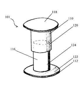
Figure 5 is a perspective front view of the rivet of the safety link of Figure
4,
Figure 6 is a perspective front view of rivet of Figure 5, after being
overloaded, and clearly
indicating this by the deformed shape, and colour shown;
Figure 7 is a plan view from above of a safety link according to a third
preferred
embodiment of the invention, similar to the first and second but including a
tag, the
attachments and lifting, winching, towing or securing apparatus or similar
apparatus
generally is not shown throughout for ease of illustration;
Figure 8 is a plan view of the safety link of Figure 7 after being overloaded,
and clearly
indicating this by the broken tag.
DETAILED DESCRIPTION OF THE INVENTION INCLUDING A BEST MODE
Referring to Figures 1 and 2, a preferred embodiment of the invention will be
described,
where safety link 1 has first loop 10, second loop 12 and joining loop 14.
Each of first loop
10, second loop 12 and joining loop 14 are formed of the same loop of strong
alloy steel,
grade 80 to 100 strength. Any suitable material may be used for safety link 1,
important
being that it is strong but will deform on overloading of the lifting,
winching, towing or
securing apparatus or similar apparatus. The lifting, winching, towing or
securing
apparatus or similar apparatus to which safety link 1, and the load itself are
not shown in
the Figures for ease of illustration. The load could be any heavy item and
often are
materials in the construction or mining industry, for example. Other uses may
be for
vehicles, boats or other lifting, winching, towing or securing apparatus or
similar or
AMENDED SHEET
1PEA/AU
CA 03070999 2020-01-24
PCT/AU2018/050789
Received 04/06/2019
17
stressed applications, anywhere it would be useful to know if undue strain had
been
applied to apparatus.
When used for standard lifting, winching, towing or securing apparatus or
similar
equipment safety link 1 can be incorporated during manufacture of the lifting,
winching,
s towing or securing apparatus or similar apparatus, or may be added between
parts
through use of a hammer lock of D shackle. The lifting, winching, towing or
securing
apparatus or similar apparatus may then be used to lift parts or heavy loads
from one
location to another, through use of attached machinery.
Figure 1 shows the arrangement of first loop 10, second loop 12 and joining
loop 14 as
id in the unused, or safely used state. Central area 16 is the area of
joining loop 14. Where
the safety link is being used for suitable loads and no overloading has
occurred safety
link 1 will appear as in Figure 1. Figure 2, by contrast, shows an overloaded
safety link 1,
clearly indicating to the user that overload has occurred, the integrity is
compromised and
that safety checks need to take place. The shape of safety link 1 means that
it deforms
15 readily on the overload, compared to a usual chain links, so that it
will indicate the
overload before the chain links fail themselves.
In one example of use first loop 10 may be attached to a chain links through
use of a D
shackle the chain links being attached to lifting, winching, towing or
securing apparatus
or similar apparatus. Another D shackle may be used to attach second look 12
to a further
20 chain links which attaches to a sling under a heavy load. The apparatus
may be retrofitted
to existing chains, slings, cables, or other suitable apparatus via a hammer
lock or D
shackle which is commonly used in the industry. Or the inventive apparatus may
be
included with apparatus, the invention is versatile in application.
Where the load is an appropriate weight for the chains, slings or cables and
equipment,
25 safety link 1 simply is maintained in place, part of the apparatus.
However, where the
lifting, winching, towing or securing apparatus or similar apparatus is
overloaded it is at
this point that safety link 1 becomes is used. During the overload the load
that is too heavy
for the apparatus is lifted and manoeuvred and the chain links are put under
stress. The
forces between the lifting, winching, towing or securing apparatus or similar
apparatus,
30 attached to first loop 10 and the load carrying part, attached to second
loop 12 will force
these two loops apart. Safety link 1 is adapted to be unchanged when suitable
loads and
forces on the respective loops are made, however, if overloaded then
deformation occurs.
AMENDED SHEET
1PEA/AU
CA 03070999 2020-01-24
PCT/AU2018/050789
Received 04/06/2019
18
As can be seen in Figure 2 once the overload has pulled apart first loop 10
and second
loop 12, joining loop 14 no longer exists, and central area 16 is open. Once
the change
has been observed in the indicator means, the person knows that the lifting
apparatus
has been overloaded and therefore can be immediately taken out of service and
safety
checks undertaken.
Referring to Figures 3 to 6 a safety rivet link 101, is included in the second
form of the
invention used with the safety link of Figures 1 and 2 of the first preferred
form of the
invention. The description of Figures 1 and 2 applies for the second
embodiment and so
is not reiterated here but with the safety rivet 101 included.
In use safety rivet link 101 is installed , at the suitable central location,
between two
connection points where if overloaded there may be a safety issue. For
example, safety
rivet link 101 may be installed in an elevator cable (not shown) to indicate
where chain
links have been overloaded and stretched, very important for safety. In this
application
first part 10 is connected to a first part of the elevator cable which may be
attached to the
lifting, winching, towing or securing apparatus or similar apparatus above.
Second part
14 is attached to another cable or to the lift itself, eg between the chain
links. The forces
between first part 10 and second part 12 in normal use would appear as in
Figure 1, no
overload has occurred. Once overload occurs the apparatus will appear as in
Figure 2.
The deformation in this form of the invention does more than deform however,
it causes
the separation of the two parts or safety rivet 101. For example, in this form
of the
invention it may be installed in a elevator cable, or connected to another
part of the
elevator cable, another cable or the lift itself. The form of the invention
may be useful in
natural disasters such as earthquakes to indicate undue stress and strain on
chain links.
When used to suspend a high voltage power lines, for example, the line may
have been
challenged by a storm, tornado, or cyclone, or hit by a falling tree. In which
case use of
the invention is very useful to indicate the need for safety checks when the
extent of the
damage may not be immediately evident. Other examples, may also be use on
sailing
vessels to indicate when the mast rigging or bracing stay cables have been
overloaded
during adverse weather or sailing conditions.
Referring to Figure 4, where the integral safety rivet link 101 when
overloaded, crushed
or ruptured in any way the design is such that this provides a clear
indication, similar to
an emergency glow stick to give out a pungent oil and dye to be visually and
by smell,
AMENDED SHEET
1PEA/AU
CA 03070999 2020-01-24
PCT/AU2018/050789
Received 04/06/2019
19
detectable. In a lift for example, a person can smell the oil even when the
chains
themselves are hidden.
Turing in more detail to safety link 101, first part 110 has head 118 and
cylinder 120. Part
112 has head 122 below with cylinder 124. Cylinder 120, in the normal use
covers cylinder
124, and so only the colour of cylinder 120 will be seen. The colour is a safe
colour such
as green, that the rivet is integral. Cylinder 124, as is only revealed on
overload or excess
stress coloured a danger colour red to provide a clear visual indication that
there has
been an overload, danger exists and the apparatus needs to be checked. On the
overload, as shown in Figure 4 not only are the two parts pulled apart, these
show the
in .. danger colour. A cover, tag or band may be included in this form of the
invention as well
to show that damage has occurred however slight, and to show that inspection
is required.
A highly visible dye used with the oil or separately can also show where the
damage or
overload has occurred and where the checks need to be concentrated. Oil or dye
or other
indications are maintained in the central region 116, similar to the central,
joining region
of the first embodiment. On overload and pulling apart it is from this central
or joining
region that the oil or dye may be released further indicating that overload
has occurred.
Referring to Figures 7 and 8, instead of a "figure of 8 shape", a tie is used,
which breaks
on overload. In this form of the invention, the method of use and apparatus is
the same
excepting the shape. Safety link 201 has first loop 210, cable tie 211 and
second loop
212. Cable tie 211 may be replaced by a plastic tie, tag or strip or other
restraint may be
included in the central location of safety link 1. As illustrated cable tie
211 is a metal tag
of green. In this form of the invention on overload the cable tie 211 or other
restraint will
be ruptured on overload. There is a clear visual indicator in this form of the
invention that
overload has occurred. For example, if cable tie 211 is broken overload the
apparatus
must be checked. As a further indication the area usually covered by cable tie
211 is a
bright colour, red as illustrated so that this can easily be seen to indicate
overload, in
addition to the broken cable tie 211. Tags, bands or strips could all be used
in this manner.
Once overloaded, the first and second parts deformed the move causes the tag,
band or
strip to break, which can be easily seen, a clear indication of the overload.
Cable tie 211
is included about the central portion of safety link 201, between first loop
210 and second
loop 212. In normal use this restraint may be seen clearly as, a green colour
perhaps,
when broken and this green colour is no visible this will indicate that
overload has
AMENDED SHEET
1PEA/AU
CA 03070999 2020-01-24
PCT/AU2018/050789
Received 04/06/2019
occurred and the integrity of the apparatus may be compromised. In another
form the
colour used to indicate a safe state, for example green, may be broken to
reveal another
colour, such as the danger colour red to visually indicate that there has been
an overload.
A combination of ties, tags and other indicators, including the shape and form
of the safety
5 link itself may all provide cues to the user that an overload has
occurred and the apparatus
should be inspected.
In any of the forms of the invention one or more indicators may be used to
indicate that
there has been an overload. The indicator may be the shape of the link, there
may be use
of ties that may be broken or lost in the case of overload. Coloured
restraints or ties may
lc be used, showing only in a safe situation or changing the colour shown
in overload has
occurred. Other safety measures may be 'included all to assist for the
operator to become
aware of the overload. For example, a pungent oil may be exuded from the
safety link if
overloaded to help bring the matter to attention. A dye may be included in the
oil, or a dye
may be used on its own from the safety link to show it has been overloaded.
Other forms
15 such as back to base electronic indications, lights or sounds could also
be used.
It will be apparent to a person skilled in the art that changes may be made to
the
embodiments disclosed herein without departing from the spirit and scope of
the invention
in its various aspects.
AMENDED SHEET
1PEA/AU
CA 03070999 2020-01-24
PCT/AU2018/050789
Received 04/06/2019
21
REFERENCE SIGNS LIST:
1 Safety Link = 201 Safety Link
First loop 210 First loop
12 Second loop 211 Tie
14 Joining loop 212 Second loop
16 Central area
101 Safety rivet link
110 First part
112 Second part
116 Central region
118 Head of 110
120 Cylinder of 110
122 Head of 112
124 Cylinder of 112
AMENDED SHEET
1PEA/AU