Note: Descriptions are shown in the official language in which they were submitted.
CA 03071139 2020-01-27
WO 2019/038018 PCT/EP2018/070294
1
A method for operating a round baler and a round baler
The present disclosure refers to a method for operating a round baler and a
round baler.
Background
A baling machine, usually existing of the round or rectangular bale type is
used to package
crop material into a round or rectangular shape.
A baling machine can be divided up into various areas of components and
apparatuses. One
of the primary components of the baler is the binding unit usually commonly
used to apply a
twine / net or a sheeted type material to the bale of product. The binding
apparatus can be
located on the baler in various locations depending on the type of machine and
its use.
Applying binding material to the bale can be a difficult process to achieve
high levels of reli-
ability. In particular, problems exist with sheeted materials in that the
surface of the material
is not of the mesh type and as a result the crop on the bale does not bond
with the binding
material as efficient as of the mesh type of binding. As a result, the binding
sheet type mate-
rial can often fail to follow the circumference of the bale and may instead
follow a rotating
component of the baling machine.
In general the machines that can apply this type of sheet binding material,
the operator
needs to manipulate the intake of crop into the machine as the binding
material is being fed
into the baling chamber so the incoming crop can enclose the first parts of
the sheet material
within layers of crop so the sheet binding material is trapped between the
crop layers and as
a result can successfully follow around the circumference of the bale
without leaving the bal-
ing chamber.
This intake of crop material to enclose the first parts of the binding
material with the crop on
the bale is not automated by the machine but instead is solely carried out by
the skill of the
operator of the machine. This is a difficult process and can also be very
unreliable as the
operator has to judge the quantity of crop entering the machine and also judge
the forward
speed correctly of the baling machine. In a standard stop start baler, the
driver needs to stop
when the baling chamber is full in order to apply the binding material, If the
driver stops too
early the first part of the binding material will not be enclosed in the bale
and the binding
material may not follow the bales circumference, if the driver drives forward
too far after the
CA 03071139 2020-01-27
WO 2019/038018 PCT/EP2018/070294
2
baling chamber is full, the first part of the binding material will be
enclosed too far beneath
the bales surface and excess crop will cover the plastic causing issues at a
later stage with
the preservation of the crop material and the removal of the binding material.
The issues
also include incorrect over lap of the binding material, excess crop between
the binding lay-
ers allowing air or and moisture to enter the bale and /or accumulative issues
when trying to
remove the binding material from the bale.
Another problem with the binding material of the sheeted plastic type is
providing a reliable
apparatus to feed the plastic into the chamber, to provide a stretching of the
plastic and then
to remove some of the braking force at the end of the binding cycle to
successfully cut the
binding material so the cycle may be successfully started again on the next
bale. Due to the
elasticity of the binding material, the braking/ stretch of the plastic sheet
material must be
removed at the end of the cycle in order to prevent excessive contraction of
the plastic bind-
ing material. If there is excessive contraction of the stretched binding
material, reliable feed-
ing of the material at the start of the next bale binding cycle may not be
possible.
Commonly, a roller is used to provide a stretch on the binding the material.
Either the brak-
ing roller is pushed onto the roll of binding material and or the binding
material is routed
around the braking roller for stretching the binding material. The binding
material may be
wrapped around the braking roller between 100 and 300 degrees of contact with
the braking
roller depending on the machine type.
The applying compressive force from the braking roller pushing onto the
circumference of
the roll of plastic may be limited because when feeding the binding material
at the start of the
binding process, it would not be possible to pull the binding material from
the roll of binding
material due to the high rolling resistance caused by the excessive
compressive forces. As a
result of this limited compressive force between the braking roller and the
roll of binding ma-
terial, limitations will exist when stretching the binding material at the
higher stretch percent-
ages.
The problem presented is, if the force of the braking roller pushing onto the
roll of binding
material is too great, the binding apparatus will be unable to draw the
binding material from
the roll of binding so the binding material can enter the baling chamber. If
the force of the
braking roller pushing on the roll of binding is not sufficient, the release
of the braking rota-
tional force at the end of the binding cycle in order to cut the material, the
momentum in the
CA 03071139 2020-01-27
WO 2019/038018 PCT/EP2018/070294
3
roll of binding material will cause the roll of material to rotate after the
binding material has
been cut and binding cycle has ended. With all of the current binding
stretching systems, the
stretching roller is always in contact with the binding material either
through the binding ma-
terial passing over, between or around the stretching roller or the stretching
roller is pushing
on the roll of binding material directly at all times. As a result, if the
stretching is excessive or
not enough, the binding material passing through the stretching roller can
overrun, pull
backwards or bind to the stretching roller and as a result, the binding
material is not free for
the start of the next binding cycle. The systems currently existing have
disadvantages of
needing to be finely tuning the forces to try and overcome the problems.
Document EP 3 132 672 Al shows a binding system with a braking/ stretching
roller and a
braking force controlled with a motor. A binding material is in constant
contact with the brak-
ing/ stretching roller at all stages of the binding cycle. As a result, the
system needs to be
finely tuned especially at the end of the cycle when cutting the binding
material so the bind-
ing material does not overrun causing the binding material to fully wrap or
become lodged on
the braking/ stretching roller.
Another example of prior art is document WO 2013 /124836 Al In this example a
braked/
stretch roller is in contact with a binding material and the binding material
also wraps around
the roller. If the binding material overruns at any point of the binding cycle
or breaks at any
point of the binding cycle, the plastic will inevitably become entangled and
fully wrapped
around the braked/ stretch roller. This is a major disadvantage with these
known binding
systems.
Summary
It is an object to provide a method for operating a round baler and a round
baler with im-
proved operation control.
.. For solving the problem a method for operating a round baler and a round
baler according to
the independent claims 1 and 10, respectively, are provided. Further
embodiments are re-
ferred to in the dependent claims.
According to an aspect, a method for operating a round baler is provided, the
method corn-
prising: providing a nonstop baler type machine; feeding of crop into a
prechamber and a
CA 03071139 2020-01-27
WO 2019/038018 PCT/EP2018/070294
4
main bale forming chamber; and providing, by a binding unit, a binding
material to the main
bale forming chamber for wrapping a bale formed in the main bale forming
chamber. The
providing is comprising: in a first mode of operation, providing a stretching
apparatus in con-
tact with the binding material, thereby, applying a compressive force to the
binding material
for stretching the binding material; and, in a second mode of operation,
providing the stretch-
ing apparatus free of contact with the binding material.
According to another aspect, a round baler is provided, comprising: a
prechamber; a main
bale forming chamber; a feed channel configured to feed crop into at least one
the precham-
ber and the main chamber; and a binding unit, comprising a stretching
apparatus. The bind-
ing unit is configured to: provide a binding material to the main bale forming
chamber for
wrapping a bale formed in the main bale forming chamber; in a first mode of
operation, pro-
vide the stretching apparatus in contact with the binding material, thereby,
applying a com-
pressive force to the binding material for stretching the binding material;
and, in a second
mode of operation, provide the stretching apparatus free of contact with the
binding material.
In the first mode of operation there is physical contact between the
stretching apparatus and
the binding material. The compressive force which in some embodiment may also
be re-
ferred to as braking force in turn will cause friction between the stretching
apparatus and the
binding material, thereby, stretching the binding material (compared to a non-
stretched con-
dition) by a certain amount adjustable by the adjusting the compressive force
applied by the
stretching apparatus.
In the second mode of operation, for the binding unit, the stretching
apparatus is removed
from contact with the binding material,
The providing may comprise providing a first stretching roller in contact with
the binding ma-
terial. The first stretching roller may be provided as or with a first braking
roller. A braking
force may be applied to the first braking roller for stretching the binding
material.
The providing may comprise providing a second stretching roller in contact
with the binding
material. The second stretching roller may be provided as or with a second
braking roller. A
braking force may be applied to the second braking roller for stretching the
binding material.
CA 03071139 2020-01-27
WO 2019/038018 PCT/EP2018/070294
The first and second stretching (braking) rollers may be moved simultaneously
for at least
one of providing the first and second stretching rollers in contact with the
binding material /
first stretching roller and for providing both the first and second stretching
rollers free of con-
tact with the binding material / first stretching roller.
5
The first and second stretching rollers may be moved by a single actuator.
Alternatively, the
first and second stretching rollers may be operated by separated actuators
each of which is
assigned to only one of the stretching rollers. In the different embodiments,
the actuator(s)
may be provided with a hydraulic and / or a mechanical mechanism such as a
spring mech-
anism for moving the stretching roller(s) against the binding material.
A first compressive force may be applied to the binding material by the
....... first stretching roller,
the first compressive force being different from a second compressive force
applied to the
binding material by the second stretching roller. Alternatively, the first and
second compres-
sive forces may be equal. Together the first and second compressive forces
provide for a
total compressive force. The first and second compressive forces may be
separately adjust-
able.
The applying may comprise applying the compressive force against a
circumference of a
binding material roller which is supporting the binding material and from
which the binding
material is unrolled for providing the binding material to the main bale
forming chamber.
The applying may comprise applying the compressive force against a side of the
binding
material, wherein an opposite side of the binding material is unsupported.
The method may comprise providing a compressive
............................... force against at least one of a surface of
the first stretching roller and a surface of the second stretching roller. The
compressive force
may be applied by pushing some braking element against the rollers surface,
thereby, caus-
ing friction between the milers surface and the braking element.
By the compressive force against the surface of at least one of the stretching
(braking) roll-
ers a second braking force may be provided, the second braking force being
provided in
addition to the compressive force (first braking force) against the binding
material. The se-
cond braking force is applied to the rotation of at least one of the first and
second stretching
(braking) rollers.
CA 03071139 2020-01-27
WO 2019/038018 PCT/EP2018/070294
6
In an example, the first compressive force (first braking force) may be
applied to the binding
material by the first (stretching) braking roller. A second compressive force
(second braking
force) may be applied to the rotation of at least one of the first and second
braking rollers
surface which results in the stretching of the binding material. The first
compressive force
may be different from secondary braking force. Thus, in this example, the
stretching of the
binding material can be adjusted by adjusting at least one of the first
compressive force (ap-
plied by the stretching roller(s) against the binding material) and the second
compressive
force (against the surface of the stretching roller(s)). A primary and a
secondary braking
mechanism are provided.
The sum of the primary braking force(s) (i.e. force applied to the binding
material by the
stretching roller) and the secondary braking force(s) (i.e. force applied to
the rotation of the
braking rollers surface) provide in totality the braking for the binding
apparatus for stretching
the binding material.
In ... the first mode of operation for the braking device or apparatus there
is physical contact
between the braking (stretching) roller(s) and the binding material. The
compressive force of
the braking roller(s) applied compresses on the binding roil. Such force may
be the result of
a primary and a secondary braking apparatus mechanism. The secondary braking
appa-
ratus which applies a positive braking force to the rotating stretching
(braking) roller(s) being
in contact with the binding material which adds to the overall braking force.
The primary
braking mechanism applies a frictional force to the braking roller to reduce
the braking rollers
rotational speed to provide the stretching rate to the binding material.
According to a further aspect, a method for operating a round baler may be
provided, com-
prising; providing a nonstop baler type machine; controlling a feeding
mechanism for feeding
of crop into a prechamber and a main bale forming chamber by a control system
of the baler;
in a feeding operation, feeding the crop through a first feeding channel into
the prechamber;
and switching the feeding operation by the control system, thereby, stopping
feeding the
crop into the prechamber and starting feeding the crop through a second
feeding channel
into a main bale forming chamber of the baler. The control system is
configured to switch the
feeding operation in response to a binding material parameter reaching a
predetermined
parameter value, the binding material provided for wrapping a bale formed in
the main bale
forming chamber.
CA 03071139 2020-01-27
WO 2019/038018 PCT/EP2018/070294
7
According to still another aspect, a round baler may provided, comprising: a
prechamber; a
main bale forming chamber; a first feed channel configured to feed crop into
the precham-
ber; a second feed channel configured to feed the crop into the main bale
forming chamber;
and a control system. The control system is configured to switch a feeding
operation for
feeding crop into the prechamber and, after stopping feeding of the crop into
the precham-
ber, starting feeding the crop into a main bale forming chamber; and to apply
the switching in
response to a binding material parameter reaching a predetermined parameter
value, the
binding material provided for wrapping a bale formed in the main bale forming
chamber. The
round baler may be a nonstop baler type machine.
The technology of applying the control system for a round baler may be
provided for the
round baler comprising the binding unit as disclosed above.
The control system may be configured to switch the feeding operation when the
binding ma-
terial reaches a predetermined location between 0 and 360 degrees on the
circumference of
the bale formed in the main bale forming chamber.
The control system may be configured to switch the feeding operation when the
binding ma-
terial reaches a predetermined value corresponding to a point in the
circumference of the
main bale forming chamber.
The control system may be configured to .. switch the
......................... feeding operation as the binding materi-
al is wrapping the bale formed in the main bale forming chamber.
The control system may be configured to switch the feeding operation when the
binding ma-
terial is wrapping the bale formed in the main bale forming chamber.
The control system may be configured to determine the length of the binding
material
wrapped around the bale, and to switch the feeding operation when the length
of the binding
material wrapped around the bale reaches a specific length.
The method may further comprise: stopping the crop from entering the main bale
forming
chamber at a predetermined value of a binding cycle for wrapping the bale by
the binding
material; and covering the binding material by a volume of the crop.
CA 03071139 2020-01-27
WO 2019/038018 PCT/EP2018/070294
8
The binding material may be provided as at least one of a plastic binding
material and a
sheet material. The binding material may provide an oxygen barrier when
wrapped around
the bale.
......................................................................... The
method may further comprise switching the feeding operation by switching a
moveable
plate in a crop channel.
With respect to the round baler, the aspects described above with respect to
the method for
operating may apply mutatis mutandis.
In a further example, a round baler for forming
............................... a bale from a crop product is provided. The
round baler comprises a prechamber provided with a first feeding channel to
feed crop into
the prechamber and a main bale forming chamber provided with a second feeding
channel
to feed crop into the main bale forming chamber. The baler further comprises a
feeding
mechanism which is configured to feed crop to the prechamber and / or to the
main bale
forming chamber. Also, the baler comprises a control system for controlling
the feeding
mechanism, wherein the control system is configured to stop feeding crop to
the prechamber
and start feeding crop to the main bale forming chamber and / or stop feeding
crop to the
main bale forming chamber and start feeding crop to the prechamber. The
control system is
configured to switch the feeding operation when the binding material has a
specific parame-
ter, e.g. a specific length.
In operation, the main bale forming chamber may be filled to form a bale of
crop material.
The binding cycle may begin prior to the main bale forming chamber reaching a
full state, as
the binding material is applied onto the bale of crop material; incoming crop
encloses a start-
ing end of the binding material into the bale of crop material. At a
predefined point, e.g. when
the binding material has a specific length and / or the binding material
reaches a predefined
location on the bales circumference, the control system may switch the crop
flow from the
main bale forming chamber to the prechamber.
In particular, the process of enclosing a first part of the binding material
at a predetermined
location on the circumference of the bale may be automated. A minimum quantity
of crop
needed to enclose the first part of the binding material in the bale's
circumference can be
defined as part of the automation of the machine's crop flow and baling
systems. For exam-
ple, the length of the binding material wrapped around the bale can be
determined. A specif-
CA 03071139 2020-01-27
WO 2019/038018 PCT/EP2018/070294
9
ic length of the binding material may lead to the conclusion that the binding
material has
reached the predetermined location so that it is ensured that some crop is
arranged on the
binding material.
In an example, the control system starts the binding of the bale prior to the
bale reaching its
100% size and density, resulting in the binding material reaching a designated
radial position
on the circumference of the bale as the bale reaches the full 100% in size and
density as
preselected parameters by the control system followed by the process of the
crop switching
paths to the prebale forming chamber.
In another example, the control system automatically adjusts (correction pro-
cess by the
control system) the starting % bale size and density of the bale control the
start-ing of the
binding and therefore at 100% bale size and density, the binding material is
seated on a pre-
selected radial point on the bales circumference as such point the crop
passage is altered
from the main bale forming chamber into the prebale forming chamber
In an example, the starting of the binding at a % bale size and density can be
altered / cor-
rected automatically by the control system depending on the result of the
previous bale, the
control system automatically calculates the finished size and density of the
bale post binding
cycle resulting in a corrective calculation to start the next binding cycle at
a later % bale size
and or density or at an earlier % bale size and density depending on the final
bale size and
density calculation of the bale post binding cycle
For another example, the control system automatically calculates and adjusts
the starting %
of the bale size and density for the binding to start resulting in a final
bale size that is con-
sistent with the initial parameters inputted into the control to have a final
bale of product that
is comparable in size and density to the actual parameters inputted or preset
on the balers
control system.
The control system may be configured to change a direction of the flow of the
crop materia
feeding into the main bale forming chamber into the prechamber. The control
system may be
programmed to alter the direction of flow of the crop material when the
binding material is
any location from 0 to 360 degrees on the bale's circumference in the main
bale forming
chamber.
CA 03071139 2020-01-27
WO 2019/038018 PCT/EP2018/070294
The linear length of the binding material may be measured as it wraps the bale
of crop in the
main bale forming chamber. When the binding material reaches a certain
predetermined set
value which corresponds to a point in the baling chamber's circumference, the
control sys-
tem may alter the direction of the crop from one chamber to the other chamber.
As a result,
5 the crop flow is automatically stopped from entering the main bale
forming chamber at a
predetermined value in the binding cycle and the binding material can be
covered by a spe-
cific volume of incoming crop which may be automatically controlled by the
control system,
therefore removing the need for an action by the operator of the machine.
10 A predetermined value selected in the control system, which may be
linearly linked to a loca-
tion in the bale chambers circumference, may not be affected by a rotational
speed of the
main bale forming chamber and / or the prechannber. The rotational speed of
the chambers
may be directly related to a linear speed at which the binding material enters
the main bale
forming chamber and follows the bales circumference. As a result, the
predetermined point
for switching the crop from one of the chambers to the other chamber will
remain the same.
A system to obtain signalled information from the machine may be provided, a
calculating
process to translate information through formulation and a means for the
formulated infor-
mation to influence the devices on the baling machine to control the crop flow
into either of
the baler's chambers may be provided.
Signalled information may be obtained and recorded from the chambers'
rotational speed. In
addition or alternatively, signalled information may be obtained from the main
bale forming
chamber concerning the pressures within the main bale forming chamber of
compressing the
crop material into a bale and signalled information may be recorded concerning
the bale size
within the main bale forming chamber.
A calculating process may be applied to provide simultaneous calculation from
the signals
received from the chambers. When a predetermined value is reached for the bale
pressure
and / or the bale size, the binding unit may be activated by the control
system. The binding
material is then fed into the main bale forming chamber. As the binding
material is fed into
the main bale forming chamber, further signalled information may be relayed
back to the
control system. The signalled information may then be processed and a
formulation process
may take place to calculate the length of the binding material entering the
main bale forming
CA 03071139 2020-01-27
WO 2019/038018 PCT/EP2018/070294
11
chamber. When a predetermined value is reached, the control system may send a
signal to
change the crop flow direction from one chamber to the other chamber.
The switching of the crop flow from one chamber to the other chamber when the
binding
material has reached a predetermined set value may be automated by the baler's
systems.
The crop may be switched from the main bale forming chamber to the prechamber
with a
moveable plate in a crop channel. Signalled information may be related back to
a processor
of the control system, and the processor may engage in a process to translate
the signalled
information into positional information to relay the position of the plate in
the crop channel.
The signalled information may later be relayed to the processor concerning the
bale size and
/ or the density of the bale. At a predetermined value for the bale density
and / or the bale
size, the processor may relay information to start the binding process.
Signalled information
may be relayed back from the binding unit's feeding roller to determine the
length of binding
material entering the main bale forming chamber. The signalled information
received by the
balers processor may be calculated using formulation resulting in a linear
length of the bind-
ing material entering the main bale forming chamber being determined. When a
preselected
length of binding material has entered the main bale forming chamber, the
processor may
signal to the control system to move the crop to the prechannber.
The control system may start the binding of the bale prior to the bale
reaching its 100% (full)
size and density, resulting in the binding material reaching a designated
radial position on
the circumference of the bale as the bale reaches the full 100% in size and
density as prese-
lected parameters by the control system followed by the process of the crop
switching paths
to the prebale forming chamber.
The control system may automatically adjust (correction process by the control
system) the
starting bale size and density (<100%) of the bale control the starting of the
binding and
therefore at 100% bale size and density, the binding material is seated on a
preselected ra-
dial point on the bales circumference as such point the crop passage is
altered from the
main bale forming chamber into the prebale forming chamber.
The starting of the binding at a starting bale size and density (<100%) can be
altered / cor-
rected automaticaily by the control system depending on the result of the
previous bale, the
control system automatically calculates the finished size and density of the
bale post binding
CA 03071139 2020-01-27
WO 2019/038018 PCT/EP2018/070294
12
cycle resulting in a corrective calculation to start the next binding cycle at
a later % bale size
and or density or at an earlier % bale size and density depending on the final
bale size and
density calculation of the bale post binding cycle
The control system may automatically calculate and adjust the starting bale
size and density
for the binding to start resulting in a final bale size that is consistent
with the initial parame-
ters inputted into the control to have a final bale of product that is
comparable in size and
density to the actual parameters inputted or preset on the balers control
system.
The control system may start the binding of the bale prior to the bale
reaching its 100% (full)
size and density, resulting in the binding material reaching a designated
radial position on
the circumference of the bale as the bale reaches the full 100% in size and
density as prese-
lected parameters by the control system followed by the process of the crop
switching paths
to the prebale forming chamber.
The control system may automatically adjust (correction process by the control
system) the
starting bale size and density (<100%) of the bale control the starting of the
binding and
therefore at 100% bale size and density, the binding material is seated on a
preselected ra-
dial point on the bales circumference as such point the crop passage is
altered from the
main bale forming chamber into the prebale forming chamber.
The starting of the binding at a starting bale size and density (<100%) can be
altered / cor-
rected automatically by the control system depending on the result of the
previous bale, the
control system automatically calculates the finished size and density of the
bale post binding
cycle resulting in a corrective calculation to start the next binding cycle at
a later % bale size
and or density or at an earlier % bale size and density depending on the final
bale size and
density calculation of the bale post binding cycle
The control system may automatically calculate and adjust the starting bale
size and density
for the binding to start resulting in a final bale size that is consistent
with the initial parame-
ters inputted into the control to have a final bale of product that is
comparable in size and
density to the actual parameters inputted or preset on the balers control
system.
CA 03071139 2020-01-27
WO 2019/038018
PCT/EP2018/070294
13
It is another aim to
a) provide a binding system with a stretching mechanism that does not need to
be finely
tuned,
b) remove the possibility of the binding material wrapping or becoming
entangled on the
stretching / braking roller at any stage during the application of binding
material to a bale
of crop during the binding cycle, and / or
c) provide the possibility to apply a compressive force from the braking
apparatus onto the
roll of binding during the stretching of the binding material.
It is also an aim to improve on the apparatus and process required to feed the
binding mate-
rial into the chamber reliably. This may be achieved by removing all contact
of the stretching
/ braking roller with the binding material at the start of the binding cycle
so all frictional forces
are removed when feeding the binding material from the roll of binding
material into the bal-
ing chamber to an accurate reliable level and / or by releasing the stretching
/brake at the
end of the binding cycle for a reliable ending to the cycle so the next
binding cycle starts
again reliably.
With regard to sheeted type binding materials, the invention aims to increase
the level of
reliability when applying a binding material to a round or rectangular bale.
A binding unit is provided. The binding unit may comprise a feeding means
which is config-
ured to feed a binding material into a baling chamber; a stretching means
which is config-
ured to stretch the binding material when wrapping the bale of material within
the baling
chamber; and / or a cutting means which is configured to cut the binding
material when the
preselected length of binding material has covered the bale.
The stretching means may comprise a stretch roller / braking roller with an
external braking
force applied to the stretch roller in order to provide a braking effect for
the binding material
while in contact with the binding material. A non-stretching means may
comprise the stretch-
ing means configured to automatically remove all external braking forces
applied to the
stretch roller while in the same configuration removing all physical contact
with the binding
material.
Also, a stretching apparatus for the binding material may comprise multiple of
modes within
one stretching means apparatus. In "feeding of the binding material into the
chamber mode,
CA 03071139 2020-01-27
WO 2019/038018 PCT/EP2018/070294
14
the stretching apparatus may remove contact with the binding material. In
"binding material
initial stretch" mode, the stretching apparatus may move the stretch roller
into a free rolling
contact with the binding material roll. In a "2nd stretch" mode, the
stretching apparatus may
apply a predetermined force to the stretch roller which applies a stretch to
the binding mate-
rial. In "initial end of cycle" mode, the braking force (compressive force)
from the stretch roll-
er may be removed and the stretch roller may remain in free rolling contact.
In "out of con-
tact" mode with the binding material roll, a "2nd end of cycle" mode may allow
the cutting of
the binding material with the application of a braking force on the stretch
roller simultaneous-
ly as the cutting action is taking place.
The binding unit may be provided with a stretching means and a non-stretching
means con-
trollable by an actuating means. The braking apparatus may comprise a means of
controlling
the braking forces to stretch the binding material and / or may comprise a
means of control-
ling the location of the stretching roller means in relation to the location
of the binding mate-
rial from physical contact with the binding material in a general forward and
reverse move-
ment.
The stretching means apparatus actuator may comprise a dual function. A single
actuating
means may remove the stretching means from contact with the binding material
and alterna-
tively may position the stretch roller combined with the braking apparatus of
the stretch roller
onto the binding material to achieve a preselected stretch ratio.
Also, a binding material stretching means may be provided. The binding
material stretching
means may comprise a stretching apparatus comprising stretching roller and
braking means,
for the stretch roller. The stretch roller may comprise dual braking means. A
secondary brak-
ing means may comprise an independent braking force on the stretch roller
provided by a
means independent of the braking apparatus of the stretch roller onto the
binding material. A
primary stretching roller braking means may be responsible for the primary
braking forces on
the binding material supplemented by the secondary braking means independent
of the pri-
mary braking means dually combining to provide the preselected binding
material stretch
ratio.
A binding material stretching means may be provided which may comprise a
stretching ap-
paratus comprising stretching roller and braking means, for the stretch
roller. The stretching
apparatus may comprise a plurality of stretching means independently applying
braking
CA 03071139 2020-01-27
WO 2019/038018 PCT/EP2018/070294
forces to the stretch roller. Primary forces may be applied through an
actuator applying a
friction means on the stretch roller to brake the stretch roller. A secondary
breaking means
may apply a secondary force to the stretch roller through the stretch roller
supporting frame
by an external force independent of the friction means providing the primary
braking means
5 on the binding material. The secondary force may create additional
frictional contact be-
tween the inner tube of the roll of binding material and a center supporting
axle while the
primary stretching means may create a braking to the rotational speed of the
stretch roller.
A binding unit may be provided. The binding unit may comprise multiple
independent braking
10 forces comprising primarily of primary and secondary forces each of
which may contribute to
the surface contact pressure applied between the binding material stretch
roller and the roll
of binding material. The primary stretching roller braking means may comprise
a friction
means to provide a braking force on the stretch roller, the same braking force
may provide a
surface contact pressure on the roll of binding material preventing slippage,
while the sec-
15 ondary independent braking force also may provide a force complementing
the primary forc-
es for surface contact pressure on the roll of binding material preventing
slippage of the
stretch rollers surface against the binding materials surface.
A binding unit with a stretching apparatus in which the stretch roller may be
removed from
surface contact with any part of the binding materials roll or layered part of
the material from
dispatching from the roll through to engagement on the bale of materials
circumference may
be provided.
The binding unit may comprise a stretching apparatus comprising of a braked
roller with
braking forces causing a reversing of the direction of the braked roller. The
braking forces
may be applied to the external face of the stretch roller through an actuator
means applying
a force to the frictional means which then may apply a force to the stretch
rollers outer sur-
face resulting in a slowing down of the circumference speed of the stretch
rollers surface
causing the binding material dispatching from the binding material roll to
slow down resulting
in speed difference between the baling chamber and the dispatched binding
material
speeds.
The binding unit may comprise a stretching apparatus comprising an actuator.
The actuator
may provide multiple actions within the binding unit, may remove the stretch
roller from con-
tact with the binding material for feeding of the binding material at the
start of the cycle, may
CA 03071139 2020-01-27
WO 2019/038018 PCT/EP2018/070294
16
engage the braking means, may apply the preselected pressure on the braking
means, e.g.
by the extension of springs, may regulate the braking means for the end of the
binding cy-
cles cutting phase and may remove the stretch roller to an area external of
that of the roll of
binding materials circumference diameter to recharge the binding unit with a
full roll of bind-
ing material.
It may be possible to apply large compressive forces between the braking
roller and the roll
of binding material which forces may not be limited by the force necessary to
puIl the binding
material from the roll of binding material at the start of the binding
process. When feeding the
binding material, the large compressive forces may be removed completely by
the function-
ality of the binding unit, for example by removing the stretch roller from
contact with the bind-
ing material.
The binding unit may be provided with a stretching apparatus that provides a
rotational / lat-
eral movement of the braking means, the stretching apparatus moving the
braking means in
a positive working direction to apply a braking force onto the roll of binding
material and
therefore onto the sheeted material dispensing from the roll of binding
material. Deactivation
of the stretch of the binding material may be provided by the stretching
apparatus and brak-
ing means moving in a direction opposite the working direction, increasing the
distance be-
tween the circumferences of the braking roller of the braking means and the
circumference
of the roll of binding material.
The binding unit may comprise a stretching apparatus with a braking means. For
braking,
the braking means may move in a positive direction towards the binding
material roll, result-
ing in the distance between the circumference of the braking means roller and
the circumfer-
ence of the roll of binding material decreasing until reaching a value of
zero. Further move-
ment in the positive direction may result in compressive forces of the braking
means against
the binding material roll.
The binding unit may comprise a stretching apparatus with a braking means,
When a work-
ing mode of the binding unit is activated, the braking means may move in a
positive direction
until the braking means braking roller's circumference makes contact with the
circumference
of the binding material. After physical contact has been made, the braking
means may apply
a compressive force to the roll of binding material.
CA 03071139 2020-01-27
WO 2019/038018
PCT/EP2018/070294
17
The binding unit comprising the stretching apparatus and the roll of binding
material may be
represented by a Venn diagram with two sets. Set one (denoted as A) may
represent the
braking apparatus and set two (denoted as B) may represent the roll of binding
material. The
intersection of the sets A and B may represent the braking apparatus being in
physical con-
tact with the circumference of the roll of binding material. The union of the
sets A and B may
represent the binding unit comprising the stretching apparatus and the roll of
binding materi-
al.
The binding unit may comprise a stretching apparatus. The stretching apparatus
may corn-
prise a braking roller. A braking force on the circumference of the braking
roller may trans-
late into a compressive force on the contact surface area between the
circumference of the
braking roller arid the circumference of the roll of binding material. An
increase in the force
on the brake may lead to an increase in the compressive force between the
braking roller
and the binding material roll. There may be a linear relationship between the
increase in
braking resistance on the braking roller and the increase of the compression
forces between
the braking roller and the roll of binding material. The compression force
between the brak-
ing roller and the roll of binding material may increase the surface friction
between the brak-
ing roller and the circumference of the roll of binding material. The increase
in surface friction
may decrease the probability of slippage occurring between the surface of the
braking roller
and the surface of the roll of binding material during the stretching of the
binding material.
Description of embodiments
Following, further embodiments are described by referring to figures. In the
figures show:
Fig. 1 a schematic representation of crop flow to the main bale forming
chamber, the crop
flow entering the chamber encloses the binding material between the outer
layer of
crop on the bale and the inner material on the bale;
Fig. 2 a schematic representation of the switching of the crop flow to the
baler's precham-
ber at a predetermined point on the bales circumference of the binding
material;
Fig. 3 a schematic representation of a binding apparatus, wherein the binding
apparatus is
provided with a braking mechanism, within the braking mechanism the stretch
roller
locates in the parked / binding roll recharge position;
Fig. 4 a schematic representation of a binding apparatus, wherein the braking
mechanism
is shown, within the braking mechanism the stretch roller locates in the
binding feed
position, located away from the binding material;
CA 03071139 2020-01-27
WO 2019/038018
PCT/EP2018/070294
18
Fig. 5 a schematic representation of the binding apparatus, wherein the
braking mecha-
nism is shown, within the braking mechanism the stretch roller locates in the
stretching position, the stretching position, the stretch roller applying a
braking force
on the binding material roil;
Fig. 6 a schematic representation of the binding apparatus, wherein the
braking mecha-
nism is shown, within the braking mechanism the stretch roller locates in the
binding
completion position; the stretch roller locates in a non contact position with
the bind-
ing material; and
Fig. 7 a schematic representation of the binding apparatus, wherein the
braking mecha-
nism is shown, within the braking mechanism the stretch roller locates in the
binding
material roll change recharge position.
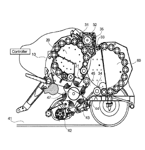
Fig. 1 shows a schematic representation of a baling machine 10 of the nonstop
type. The
baling machine 10 is provided with a prechamber 20 in which a preformed bale
is prepared
in the process of forming a bale from crop 41. There is a feeding channel 21
configured to
feed the crop 41 picked up by a crop pickup mechanism 42 to the prechamber 20.
There is a second feeding channel 45 for feeding or guiding the crop 41 into a
main baling
forming chamber 60. In the main bale forming chamber 60 a full bale of crop
material is pre-
pared.
A crop cutting device 43 is provided. A crop switching plate 44 can be pivoted
on the rear
side of the crop cutting device 43 for guiding the crop 41 to at least one of
the prechamber
20 and the main bale forming chamber 60.
The feeding of the crop 41 is conducted by a feeding mechanism 47.
While according to Fig. 1 the crop 41 is fed to the main bale forming chamber
60, the crop
41 is fed to the prechamber 20 according to Fig. 2 when the crop switching
plate 44 is in a
different position compared to Fig. 1.
A binding apparatus 31 is provided for the baling machine 10. The binding
apparatus 31 is
provided with a roll 32 of binding material. A binding material pathway 33 is
provided. A tail
end 34 of the binding materiai is on the circumference of the bale 11.
CA 03071139 2020-01-27
WO 2019/038018
PCT/EP2018/070294
19
Further, a feeding roller 35 is provided for the binding apparatus 31.
Referring to Fig. 3 to 7, further aspects are described, specifically with
respect to the binding
apparatus 31 provided in a binding unit 100.
In Fig. 3 to 6 bale chamber rollers 102 are depicted applied for forming the
bale 11.
A braking apparatus structure 111 is provided.
There are binding material guide rollers 112.
The binding unit 100 is provided with a frame 113. With respect to the binding
unit 100, a
binding apparatus grouping mechanism 114 and a binding material cutting
mechanism 115
are provided.
A part 116 of the binding material is entering the main bale forming chamber
60 between
one of the bale chamber rollers 102 and the circumference of the bale 11.
The binding material is provided by a roll of binding material 117. The
binding material is
moved along a path 118 when leaving the roll of binding material 117
A stretch roller 119 (stretching / braking roller) is provided.
A secondary force depicted by reference numeral 120 is applied to the stretch
roller 119.
There is a braking roller 121 of the braking apparatus structure 111 for
providing a braking
mechanism.
A primary force depicted by reference numeral 122 is applied to the stretch
roller 119.
There is a primary force monitoring device 123.
A connecting rod 124 is connecting an actuator for braking in the brake
mechanism.
Further, a binding material feeding roller 125 is provided.
CA 03071139 2020-01-27
WO 2019/038018 PCT/EP2018/070294
Fig. 3 shows a schematic representation of a binding apparatus, wherein the
binding appa-
ratus is provided with a braking mechanism, within the braking mechanism the
stretch roller
locates in the parked / binding roll recharge position. In this state, the
binding unit 31 is in a
switch over state, the braking mechanism 121 is lifted into a home position so
the binding
5 material roll can be recharged when the binding material 117 goes empty.
Fig. 4 shows a schematic representation of a binding apparatus, wherein the
braking mech-
anism is shown, within the braking mechanism the stretch roller locates in the
binding feed
position, located away from the binding material. The binding unit 31 is now
engaged in the
10 working mode, the roll of binding material 121 is in position and the
braking mechanism 121
is lifted from the binding materials surface so the binding material can be
pulled from the roll
and fed into the baling chamber 60. The binding material follows a path 118
from the circum-
ference of the binding material roll over the guiding rollers 112, between the
plastic grouping
sys-tem 114, through the binding systems feeding rollers and cutting mechanism
and in-to
15 .. the baling chamber 60.
Fig. 6 shows a schematic representation of the binding apparatus, wherein the
braking
mechanism is shown, within the braking mechanism the stretch roller locates in
the binding
completion position. The primary braking apparatus is removed from the
stretching roller
20 locates, the roll of binding material 117 is in position and the primary
braking mechanism 121
is lifted from the braking roller so the binding material can be cut by the
binding unit 31 knife
unit 115.
Fig. 7 shows a schematic representation of the binding apparatus, wherein the
braking
....... mechanism is shown, within the primary braking apparatus 121 is
removed from the braking
roller and the secondary braking force 120 is removed by the lifting of the
braking roller 119
from being in contact with the binding material 117.
The features disclosed in this specification, the figures and / or the claims
may be material
for the realization of various embodiments, taken in isolation or in various
combinations
thereof.
CA 03071139 2020-01-27
WO 2019/038018 PCT/EP2018/070294
21
Reference list
Baling machine of the nonstop type
11 Bale
5 20 Prechamber
21 Feeding channel entering the prechamber
31 Binding apparatus
32 Roll of binding material
33 Binding material and binding material pathway
10 34 Tail end of the binding material on the bale's circumference
35 Feeding roller and binding material cutting mechanism
42 Crop pickup mechanism
43 Crop cutting device
44 Crop switching plate pivoting on the rear side of the crop cutting
device, in this position
guides crop to the main bale forming chamber
45 Crop channel for guiding crop into the main baling chamber
46 Crop switching plate pivoting on the rear side of the crop cutting
device, in this position
guides crop to the main bale forming chamber
47 Feeding mechanism
60 Main bale forming chamber with a full bale of material
100 Binding unit
102 Bale chamber rollers
103 Bale of material
111 Braking apparatus structure
112 Binding material guide rollers
113 Frame of binding unit
114 Binding apparatus grouping mechanism
115 Binding material cutting mechanism
116 Binding material entering bale chamber between roller and bale
circumference
117 Roll of binding material
118 Path of binding material leaving from the roll of binding material
119 Stretch roller (Stretching / braking roller)
120 Secondary force applied to the braking roller
121 Braking roller braking mechanism
122 Primary force applied to braking roller mechanism
CA 03071139 2020-01-27
WO 2019/038018
PCT/EP2018/070294
22
123 Primary force monitoring device
124 Connecting rod, connecting actuator to braking roller brake mechanism
125 Binding material feeding roller