Note: Descriptions are shown in the official language in which they were submitted.
CA 03071281 2020-01-27
WO 2019/232205 PCT/US2019/034647
METHODS AND SYSTEM FOR HOMOGENEOUS DENTAL APPLIANCE
CROSS-REFERENCE TO RELATED APPLICATIONS
[0001] The present application is a non-provisional filing of, and claims
benefit under 35 U.S.C. 119(e)
from, U.S. Provisional Patent Application Serial No. 62/679,007, entitled
"Methods and System for
Homogeneous Dental Appliance," filed May 31, 2018, which is hereby
incorporated by reference in its
entirety.
BACKGROUND
[0002] Sleep apnea and obstructive sleep apnea treatments include surgery,
positive airflow machinery,
such as CPAP machines, and dental appliances. One known dental appliance is
the "Elastic Mandiblular
Advancement" (EMA ) and related appliances. The EMA appliance operates by
providing increased
airflow by forward mandibular advancement. One problem with the EMA appliance
is the risk that button
protrusions that attach to elastic bands on each side of the appliance will
detach from the appliance. One
method of attaching the button protrusions on each side of the appliance
includes cementing. However,
cementing the button protrusions can result in detachment over time and with
increased use. What is
needed is a dental appliance that has a lower risk of button protrusion
detachment.
SUMMARY
[0003] Some embodiments of a method may include receiving oral
characteristic data of a patient;
processing the oral characteristic data in a server to determine dentition
data, a vertical displacement and a
forward mandibular position to enable the patient to breathe during sleep by
opening an airway of the
patient; and forming a dental appliance via direct manufacture using the
dentition data, the vertical
displacement and the forward mandibular position, the dental appliance
including a lower dental tray and
an upper dental tray, each of the lower dental tray and the upper dental tray
being homogeneous, the lower
dental tray inclusive of the vertical displacement and a first pair of button
protrusions, the upper dental tray
inclusive of a second pair of button protrusions, the first pair of button
protrusions and the second pair of
button protrusions providing the forward mandibular position when two elastic
bands are attached to
connect the upper dental tray and the lower dental tray.
- 1 -
CA 03071281 2020-01-27
WO 2019/232205 PCT/US2019/034647
[0004] In one or more embodiments, the dental appliance is formed by three-
dimensional (3D) printing
of one or more of a light polymerizable liquid thermoset crosslinked polymer,
a polyurethane, a
methacrylate or a copolymer.
[0005] In one or more embodiments, the dental appliance is formed by three-
dimensional (3D) printing
of a polymerizable resin composition of a urethane monomer of urethane
dimethacrylate (UDMA), an acidic
monomer, and one or more hydrophobic monomers.
[0006] In one or more embodiments, the dental appliance is milled or
injection molded from one or more
of an Ethylene Propylene Copolymer and a Polyoxymethlene Copolymer.
[0007] In one or more embodiments, the dental appliance is injection molded
using one or more of
thermoplastic olefin, thermoplastic polyolefin, and olefinic thermoplastic
elastomer.
[0008] In one or more embodiments receiving oral characteristic data of the
patient includes scanning by
a scanner or camera a mold of the teeth; and transmitting the oral
characteristic data to a server.
[0009] In one or more embodiments receiving oral characteristic data of a
patient includes scanning by a
scanner of an oral cavity of the patient; imaging the oral cavity to determine
the dentition data, wherein the
oral characteristic data includes dentition data as one or more images of
teeth and a gum line of the patient
and one or more images of a soft palate of the patient; and transmitting the
oral characteristic to a server.
[0010] In one or more embodiments the method includes determining via the
oral characteristic data the
vertical displacement as a function of a shape of the soft palate of the
patient.
[0011] In one or more embodiments the determining via the oral
characteristic the vertical displacement
as a function of the shape of the soft palate of the patient includes
determining a vertical displacement of
between 5 and 7 millimeters if the soft palate has between 5 to 7 millimeters
of space between a posterior
edge of the soft palate to a posterior wall of an oral pharynx of the patient.
[0012] In one or more embodiments, the determining via the oral
characteristic data the vertical
displacement as a function of the shape of the soft palate of the patient
includes processing the oral
characteristic data to measure a distance from a gingival-tooth crown juncture
of a maxillary central to a
gingival-tooth crown juncture of a mandibular central.
[0013] In one or more embodiments the determining via the oral
characteristic data the vertical
displacement as a function of the shape of the soft palate of the patient
includes determining if a posterior
edge of the soft palate is longer than a normal soft palate with between 3 and
5 millimeters of space
between a posterior edge of the soft palate to a posterior wall of an oral
pharynx of the patient; and
providing the vertical displacement of between 8 and 10 millimeters.
- 2 -
CA 03071281 2020-01-27
WO 2019/232205 PCT/US2019/034647
[0014] In one or more embodiments the determining via the oral
characteristic data the vertical
displacement as a function of the shape of the soft palate of the patient
includes determining if a posterior
edge of the soft palate is longer than a normal soft palate and webbed and
wherein two millimeters or less
of space exists between the soft palate and a posterior wall of an oral
pharynx, providing at least 11 to 14
millimeters for the vertical displacement.
[0015] In one or more embodiments the determining via the oral
characteristic data the vertical
displacement as a function of the shape of the soft palate of the patient
includes determining whether the
soft palate is one of short, normal, and long.
[0016] In one or more embodiments the lower dental tray is inclusive of a
first vertical displacement bite
pad on a left side of the lower dental tray and a second vertical displacement
bite pad on a right side of the
lower dental tray wherein a height of each of the first and second vertical
displacement bite pads is
determined according to the oral characteristic data, the oral characteristic
data providing soft tissue data of
the patient indicative of airway function.
[0017] In one or more embodiments the vertical displacement is provided by
a thickness of the lower
dental tray.
[0018] Another embodiment is directed to a system including a processor and a
non-transitory
computer-readable storage medium storing instructions operative when executed
on the processor to
perform a method including receiving oral characteristic data of a patient;
processing the oral characteristic
data in a server to determine dentition data, a vertical displacement and a
forward mandibular position to
enable the patient to breathe during sleep by opening an airway of the
patient; and forming a dental
appliance via direct manufacture using the dentition data, the vertical
displacement and the forward
mandibular position, the dental appliance including a lower dental tray and an
upper dental tray, each of the
lower dental tray and the upper dental tray being homogeneous, the lower
dental tray inclusive of a vertical
displacement bite pad with the vertical displacement and a first pair of
button protrusions, the upper dental
tray inclusive of a second pair of button protrusions, the first pair of
button protrusions and the second pair
of button protrusions providing the forward mandibular position when two
elastic bands are attached to
connect the upper dental tray and the lower dental tray.
[0019] Another embodiment is directed to a method including receiving, by a
server, one or more data
sets associated with a patient; determining, by the server one or more
positions for placement of button
protrusions based on the received data sets from a scanner, the received data
sets including at least a
dentition pattern, a gum line, a soft palate measurement of a soft palate
shape of the patient and a uvula
placement measurement with respect to the palate shape of the patient;
communicating, by the server the
one or more positions for placement of button protrusions and a vertical
displacement, the communicating
- 3 -
CA 03071281 2020-01-27
WO 2019/232205 PCT/US2019/034647
including assigning a value associated with each of the one or more positions
for placement of button
protrusions, each value representative of a distance between an upper tray
button protrusion and a lower
tray button protrusion for mandibular advancement; transmitting the value data
to one or more of a three-
dimensional printer, a milling apparatus and an injection molding apparatus;
forming a dental appliance via
direct manufacture using the value associated with each of the one or more
positions for placement of
button protrusions, the dental appliance including a lower dental tray and an
upper dental tray, each of the
lower dental tray and the upper dental tray being homogeneous, the lower
dental tray inclusive of the
vertical displacement and a first pair of the button protrusions, the upper
dental tray inclusive of a second
pair of the button protrusions, the first pair of button protrusions and the
second pair of button protrusions
providing the forward mandibular position when two elastic bands are attached
to connect the upper dental
tray and the lower dental tray.
[0020] In one or more embodiments, the dental appliance is formed by three-
dimensional (3D) printing
of one or more of a light polymerizable liquid thermoset crosslinked polymer,
a polyurethane, a
methacrylate and a copolymer.
[0021] In one or more embodiments, the dental appliance is one or more of
milled and injection molded
using one or more of an Ethylene Propylene Copolymer and a Polyoxymethlene
Copolymer.
[0022] In one or more embodiments, the dental appliance is formed by three-
dimensional (3D) printing
of a polymerizable resin composition of a urethane monomer of urethane
dimethacrylate (UDMA), an acidic
monomer, and one or more hydrophobic monomers.
[0023] In one or more embodiments, the dental appliance is injection molded
using a thermoplastic
olefin, thermoplastic polyolefin, or olefinic thermoplastic elastomer.
[0024] In one or more embodiments, the vertical displacement is a function
of the soft palate shape of
the patient.
[0025] In one or more embodiments, the vertical displacement is provided by
one or more of a pair of
bite pads on the lower dental tray or by a thickness of the lower dental tray.
[0026] In one or more embodiments, the gum line determination identifies a
maxillary tooth crown-
gingival junction and a mandibular tooth crown-gingival junction, the upper
dental tray is formed to reach
about a three millimeter distance below the maxillary tooth crown-gingival
junction on the upper dental tray,
and the lower dental tray is formed to reach about three millimeters below the
mandibular tooth crown-
gingival junction.
[0027] Some embodiments include a processor and a non-transitory computer-
readable storage
medium storing instructions operative when executed on the processor to
perform the methods herein
described.
- 4 -
CA 03071281 2020-01-27
WO 2019/232205 PCT/US2019/034647
BRIEF DESCRIPTION OF THE DRAWINGS
[0028] FIG. 1A illustrates a system and network environment including a
computing device in
accordance with one or more embodiments of the present disclosure.
[0029] FIG. 1B illustrates a processor and a computing device in accordance
with one or more
embodiments of the present disclosure.
[0030] FIG. 2 illustrates a network environment in accordance with one or
more embodiments of the
present disclosure.
[0031] FIG. 3 illustrates a milling machine in accordance with one or more
embodiments of the present
disclosure.
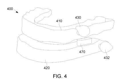
[0032] FIG. 4 illustrates a homogeneous dental appliance including button
protrusions and a vertical
displacement bite pad by direct manufacture in accordance with one or more
embodiments of the present
disclosure.
[0033] FIG. 5 illustrates an exemplary thermal injection mold for creating
a homogeneous dental tray by
direct manufacture in accordance with one or more embodiments of the present
disclosure.
[0034] FIG. 6 illustrates a negative portion of a thermal injection mold
for a bottom dental tray in
accordance with one or more embodiments of the present disclosure.
[0035] FIG. 7 illustrates a positive portion of a thermal injection mold
for a bottom dental tray to be used
with the mold of FIG. 6 in accordance with one or more embodiments of the
present disclosure.
[0036] FIG. 8 illustrates a negative portion of a thermal injection mold
for an upper dental tray in
accordance with one or more embodiments of the present disclosure.
[0037] FIG. 9 illustrates a positive portion of a thermal injection mold
for an upper dental tray to be used
with mold of FIG. 8 in accordance with one or more embodiments of the present
disclosure.
[0038] FIG. 10 illustrates a process for milling a solid material "puck"
into a dental tray by direct
manufacture in accordance with one or more embodiments of the present
disclosure.
[0039] FIG. 11 illustrates a dental appliance with elastic bands attached
in accordance with an
embodiment of the present disclosure.
[0040] FIG. 12 illustrates a profile of a patient's oral cavity
illustrating a short soft palate in accordance
with one or more embodiments of the present disclosure.
[0041] FIG. 13 illustrates an open mouth of a patient illustrating a normal
soft palate and uvula in
accordance with one or more embodiments of the present disclosure.
- 5 -
CA 03071281 2020-01-27
WO 2019/232205 PCT/US2019/034647
[0042] FIG. 14 illustrates a profile of a patient's oral cavity
illustrating a normal soft palate in accordance
with one or more embodiments of the present disclosure.
[0043] FIG. 15 illustrates an open mouth of a patient illustrating a long
soft palate and uvula in
accordance with one or more embodiments of the present disclosure.
[0044] FIG. 16 illustrates a profile of a patient's oral cavity
illustrating a long soft palate in accordance
with one or more embodiments of the present disclosure.
[0045] FIG. 17 illustrates an open mouth of a patient illustrating a long
soft palate and uvula in
accordance with one or more embodiments of the present disclosure.
[0046] FIG. 18 illustrates a dental appliance disposed on a mold of a
patient's teeth in an open position
in accordance with one or more embodiments of the present disclosure.
DETAILED DESCRIPTION
[0047] In the following detailed description, reference is made to the
accompanying drawings, which
form a part hereof. In the drawings, similar symbols typically identify
similar components, unless context
dictates otherwise. The illustrative embodiments described in the detailed
description, drawings, and
claims are not meant to be limiting. Other embodiments may be utilized, and
other changes may be made,
without departing from the spirit or scope of the subject matter presented
here.
[0048] Referring now to FIG. 1A, the figure illustrates a computing device
10 connected via a network
interface to a computer server 30 in an exemplary environment 100. As will be
further described herein the
illustrated computing device 10 and computer server 30 may employ the
computationally implemented
methods, systems, and articles of manufacture in accordance with various
embodiments. The computing
device 10 and computer server 30, in various embodiments, enable functions of
the computing device 10.
[0049] Computing device 10 illustrated in FIG. 1A can be a tablet computer,
in alternative embodiments,
the computationally implemented methods, systems, and articles of manufacture
in accordance with
various embodiments may be embodied in other types of computer systems having
other form factors
including other types of portable computing devices such as, for example,
mobile telephones, laptops,
smartphones, e-readers, and so forth. Computing devices can include
smartphones, client computers and
the like as possible computing devices. As illustrated, the computing device
10 can include a display, such
as a touchscreen as input/output of the computing device 10. Computing device
10 can further include a
keyboard, either as a touch input/output keyboard or as an attached keyboard.
As further depicted, the
computing device 10 may also be connected to a scanner 16. In one embodiment,
scanner 16 can be a
scanning camera capable of creating a 3D image of teeth.
- 6 -
CA 03071281 2020-01-27
WO 2019/232205 PCT/US2019/034647
[0050] Referring now to FIG. 1B, computing device 10 is further illustrated
with logic modules 102,
network interface 104, user interface 110, processors 116 and memory 114.
Logic modules 102 can be
implemented using circuit components such as ASIC, logic modules 102 and other
modules shown, may
be implemented using a combination of specifically designed circuitry such as
ASIC and one or more
processors 116 (or other types of circuitry such as field programmable gate
arrays or FPGAs) executing
computer readable instructions 152. For example, in some embodiments, at least
one of the logic modules
may be implemented using specially designed circuitry (e.g., ASIC) while a
second logic module may be
implemented using a processor 116 (or other types of programmable circuitry
such as an FPGA) executing
computer readable instructions 152 (e.g., software and/or firmware). System
requirements could dictate a
combination of software and firmware and circuitry to meet the embodiments
herein, for example, logic
modules could be designed to use the most efficient combination of
software/hardware/firmware in order to
quickly implement methods and systems within the scope of the present
disclosure. In some embodiments,
a Computer-Aided Design/Computer-Aided Manufacture (CAD/CAM) program operates
to implement
methods herein for forming a dental appliance from scanned images. For
example, a CAD program can
create data in a three-dimensional format and transmit the data to a
manufacturing device, such as a 3D
printer, milling machine, or injection mold creation device. Methods herein
include using patient-oriented
oral characteristic data to determine placement of button protrusions and
vertical displacement
automatically by categorizing a patient's sleep apnea needs according to soft
tissue characteristics and
dentition. Soft tissue as described herein refers to soft palate, gum line,
uvula placement as well as hyoid
tissue and the like in an oral cavity of a patient.
[0051] In various embodiments, the memory 114 of the computing device 10 may
comprise of one or
more of mass storage device, read-only memory (ROM), programmable read-only
memory (PROM),
erasable programmable read-only memory (EPROM), cache memory such as random
access memory
(RAM), flash memory, synchronous random access memory (SRAM), dynamic random
access memory
(DRAM), and/or other types of memory devices. In various embodiments, the one
or more applications 160
stored in memory 114 may include, for example, an operating system 162, a
browser(s) 163, and one or
more productivity applications 164 such as a word processing application or an
imaging application,
scanning application and one or more communication applications 166.
[0052] Computing device 10 may also include access restricting module 106.
Access restricting module
106 of the computing device 10 can be configured to restrict access via the
computing device 10 or
preventing one or more actions by computing device 10. Computing device 10 may
also include appliance
generation module 108 coupled to access restricting module 106 via a bus.
- 7 -
CA 03071281 2020-01-27
WO 2019/232205 PCT/US2019/034647
[0053] Referring to FIG. 2, appliance generation module 108 may be
configured to determine that a first
user 20 is an authorized user attempting to operate computing device 10.
Appliance generation module
108 can also be configured to determine an established authorized user based
on network received data
while computing device 10 is connected to a network connection 50. In the case
of appliance generation
module 108, existing in a cloud computing setting or computer server 30,
appliance generation module 108
may be configured to determine a network-based authorization for the first
user when first logging into
network 50 or cloud computing logging to computer server 30.
[0054] Appliance generation module 108 can be configured to receive inputs
from a scanner 16. In
some embodiments, appliance generation module 108 is coupled to a milling
device, a three-dimensional
printer, or an injection mold creation device. Appliance generation module 108
can receive CAD/CAM data
or other oral characteristic data and/or dentition data to enable creation of
a dental appliance in accordance
with one or more embodiments herein.
[0055] Computer server 30 connecting via network 50 to the computing device 10
of FIG. 1A and 1B can
establish and/or determine a vertical displacement and a forward mandibular
position for treating sleep
apnea. For example, scanner 16 and/or molds of a patient's teeth can be
examined and used to determine
the adjustment needed for treating sleep apnea. Upper and lower trays
including button protrusions can be
created from molds. For instance, a patient with malocclusion and sleep apnea
will require a determination
via scanner 16 or other method. Each patient, depending on the results of
scanned teeth and soft tissue
and patient feedback, may require a different placement of horizontal and
vertical displacement for both
treating sleep apnea. Vertical displacement can be by way of lower bite pads
or by way of the thickness of
a lower dental tray. In embodiments, the vertical displacement is part of the
mold, milled appliance or 3D
printed dental appliance.
[0056] In one embodiment, the mold(s) enables pouring of an FDA approved
material such as a
thermoplastic material or nylon to form an upper and lower tray adapted to fit
tightly but removably over
upper and lower teeth such that the lower tray creates the forward mandibular
position with respect to the
upper tray when elastic material is releasably attached to the forward and the
rearward portions of the
opposite sides of the upper and lower trays, respectively, to enable the
forward mandibular position of the
lower tray with respect to the upper tray. Button protrusions on the lower
dental tray and on the dental
upper tray are arranged to enable elastic bands to attach thereto. In one
embodiment, the button
protrusions are included as part of the mold for injection molding, milled
from a "puck" for the dental
appliance trays, or directly manufactured during 3D printing.
[0057] One embodiment includes determining a dimension and elasticity for one
or more removably
attachable elastic bands adapted to connect the upper and lower tray via
protrusions on each of the upper
- 8 -
CA 03071281 2020-01-27
WO 2019/232205 PCT/US2019/034647
and the lower trays such that the elastic bands create the forward mandibular
position of the lower tray with
respect to the upper tray.
[0058] The elastic bands can include a plurality of pairs of elastic bands,
each pair being of different
length and/or elasticity.
[0059] In one embodiment, the dental appliance is configured to be worn
during sleep. Referring now to
FIG. 3, the dental appliance can include upper and lower trays that are
manufactured using three-
dimensional (3D) technologies such as 3D printing or 3D data collection via
scanning or the like, that can
be sent to a milling device 300, as shown in FIG. 3. The resulting dental
appliance is shown in FIG. 4.
[0060] Referring now to FIG. 4, the dental appliance 400 is shown including
an upper tray 410, lower
tray 420, upper button protrusion 450, lower button protrusion 460 and bite
pad 470. Unlike other dental
appliances that include button protrusions and lower bite pads, embodiments
herein include bite pads that
are not integral with the lower button protrusion but are directly
manufactured as part of the dental tray.
Direct manufacture, as used herein refers to forming a dental appliance
homogeneously in that different
parts, such as button protrusions and vertical displacement bite pads
appropriate for a patient are
manufactured at the same time as the dental trays themselves and incorporated
into either a mold, a milled
material or printed by a three-dimensional printer.
[0061] The materials appropriate for a three-dimensional printer can be
resin-type materials and
materials described in U.S. Patent No. 9,682,018 to Sadowsky et al., June 20,
2017, "Denture Tooth and
Material" which is hereby incorporated by reference in its entirety. As one of
skill in the art will appreciate,
materials appropriate for dental appliances must be FDA approved. Appropriate
materials for resins is
further described in Tanaka J, Hashimoto T., Stansbury JW, Antonucci JM,
Suzuki K., "Polymer Properties
of Resins Composed of UDMA an Methacrylates With the Carboxyl Group" Dental
Material Journal 2001;
10:206-215, which incorporated by reference herein in its entirety.
[0062] Three-dimensional printing, as referred to herein include, but is
not limited to, stereolithography
(SLA), micro-stereolithography (pSLA), DLP projection, 2PP (two photon
polymerization), continuous liquid
interface production and material jetting. In embodiments, three-dimensional
printing includes a layer-by-
layer printing with successive layers formed in discrete layers. For example,
a surface with a build plate
immersed in a reservoir of a formulation of a polymer/resin component can be
exposed to light at
wavelengths and intensity to activate a photoinitiator to cause
photopolymerization. As one of skill in the art
will appreciate, there are other methods of three-dimensional printing such as
continuous liquid interphase
printing, in which dental trays are built up from a reservoir of
photopolymerizable resin. Continuous liquid
interphase printing is described in U.S. Patent Publication Nos. 2015/0097315,
2015/0097316, and
2015/0102532, the disclosures of each of which are incorporated herein by
reference in their entirety.
- 9 -
CA 03071281 2020-01-27
WO 2019/232205 PCT/US2019/034647
[0063] In some embodiments, the dental appliance can be formed via
injection molding. For example,
two molds such as mold 500 illustrated in FIG. 5 can be used to the upper and
lower dental trays.
[0064] Referring now to FIG. 6, a portion of a mold illustrating a negative
of a bottom dental tray 600 is
illustrated. Specifically, mold 600 includes negative teeth 640, and negative
button protrusions such as 610
and a negative for bite pads, such as 620. Referring now to FIG. 7, a positive
mold for the bottom dental
tray 700 is shown. Positive mold 700 includes button protrusions such as 710,
bite pad 720 and teeth 740.
[0065] Referring now to FIG. 8, a similar mold to FIG. 6 is illustrated,
showing a negative of an upper
dental tray. As shown, negative mold 800 includes button protrusions 810, 812
and negative teeth 840.
Referring to FIG. 9, a positive mold 900 for the upper dental tray is shown,
including button protrusions
910, 912 and teeth 940.
[0066] Referring now to FIG. 10, a milling process 1000 is shown including
a solid material, or "puck"
1010, milled for an upper dental tray made from an FDA approved material. In
one or more embodiments,
the material being milled can be an Ethylene Propylene Copolymer or a
Polyoxymethlene Copolymer. In
other embodiments, the material can be an thermoplastic olefin, thermoplastic
polyolefin, or olefinic
thermoplastic elastomer. As one of skill in the art will appreciate, different
materials can be turned into
"pucks" for milling.
[0067] During the process, the button protrusions 1010 are milled as shown
in 1020. Next, as shown in
1030, the upper dental tray of a dental appliance is milled from the puck. The
bottom dental tray can be
milled in a similar process. Thus, the dental appliance can be milled such
that the button protrusions and/or
the dental pads on the lower dental tray are part of one homogeneous dental
tray by direct manufacturing
independent of later gluing or cementing of the button protrusions and bite
pads.
[0068] Thus, as shown above, the upper and lower dental trays of a dental
appliance can be directly
manufactured using a milled process, injection molded process and/or 3D
technology. Material appropriate
for injection molding of dental appliances include thermoplastics,
thermoplastic elastomers and the like. In
one or Ethylene Propylene Copolymer or a Polyoxymethlene Copolymer. In other
embodiments, the
material can be an thermoplastic olefin, thermoplastic polyolefin, or olefinic
thermoplastic elastomer
Material appropriate for 3D printing technology include thermoset polymers
such as light polymerizable
liquid materials. In one or more embodiments, the material appropriate for 3D
printing includes a
crosslinked polymer, such as a polyurethane, a methacrylate or a copolymer. In
some embodiments, 3D
printing materials can include nylon materials.
[0069] In one or more embodiments, the materials used for milling and/or
injection molding can be
provided by Myerson Tooth, Inc., including VisiClearTM, and DuraFlexTM, which
are Ethylene Propylene
Copolymers having the following properties as shown in Table 1:
-10-
CA 03071281 2020-01-27
WO 2019/232205
PCT/US2019/034647
[0070] Table 1
Test
Physical Method Nominal Value Unit
Density-Specific Gravity (Method B) ASTM D792 .902 sp gr
23/23 C
Melt Mass-Flow Rate
ASTM D1238 40 g/10 min
(MFR)
Mechanical
Tensile Strength @ Yield ASTM D638 4060 psi
Tensile Elongation @ Yld ASTM D638 12.00%
1% Secant: 145000
Flexural Modulus (Procedure A) ASTM D790
psi
Impact
Notched lzod Impact
ASTM D256 .0899 ft lb/in
Thermal
DTUL @66p5i ¨
ASTM D648 194 F
Unannealed
Optical
Haze ASTM D1003 6.00%
[0071] In another embodiment, the milled or the injection molding material
can be provided by
DuraCetalTM, also available from Myerson Tooth, Inc., which is a
Polyoxymethlene Copolymer with the
following properties shown in Table 2:
TABLE 2
Test
Physical Nominal Value Unit
Method
Specific Gravity ASTM D792 1.41
Melt Mass-Flow Rate ASTM
(MFR) D1238
Mechanical
Tensile Strength ASTM D638 8800 psi
Tensile Elongation ASTM D638 60.00%
Flexural Modulus ASTM D790 .38 psi x 106
Impact
Impact Strength, lzod, ASTM D256 1 ft-lb/in
notched 1/8 in (3.18 mm) section
Thermal
Deflection
Temperature
ASTM 648
@ 264 psi
(1.82 Mpa)
-11-
CA 03071281 2020-01-27
WO 2019/232205 PCT/US2019/034647
Deflection
Temperature
ASTM D648 315 fC
@ 66psi
(0.45 Mpa)
[0072] Referring now to FIG. 11, dental appliance 1100 is illustrated with
an upper dental tray 1102 and
lower dental tray 1104 with elastic bands connecting either side of the dental
appliance. As shown, on a left
side of the dental appliance, an elastic band 1108 is shown connecting button
protrusion button 1110 and
1120.
[0073] The resulting dental appliance, from injection molding, milling, or
3D printing beneficially does not
require added components other than elastic bands as shown in FIG. 11 because
dental appliance is direct
manufactured such that the button protrusions and mandibular bite pads do not
have to be added later, but
homogeneously included in molds, milled pucks or via a 3D generation machine.
Prior to the direct
manufacturing as disclosed herein, dental trays required different components
such as button protrusions
and bite pads to be added by gluing or the like or encased in a thermoforming
(nonmilled) method.
[0074] Because direct manufacturing requires placement of button
protrusions and bite pads during
manufacture of the dental appliance as a whole, the measurements for
determining where the button
protrusions and the bite pads for each patient are determined prior to the
making of the homogeneous
dental trays. Referring back to FIG. 1A, scanner/camera 16, in one embodiment,
includes a determination
of the necessary oral characteristic data, including dentition data, which can
include teeth data and soft
palate data, to determine proper placement of button protrusions and bite
pads.
[0075] In one or more embodiments, a method includes determining the amount
of vertical component,
or height of bite pads for the dental appliance as a function of the shape of
the soft palate. In other
embodiments, the vertical displacement is determined by the soft tissue of the
patient, such as the hyoid
shape. In one or more embodiments, a scanner and/or camera such as
scanner/camera 16 detects shape
of soft palate. The data is collected as oral characteristic data and provided
to a processor which operates
to classify the oral characteristics for fabrication of the homogeneous
appliance.
[0076] In one or more embodiments, there are three classifications for a
soft palate: short, normal or
long. Thus, in one or more embodiments, a method includes determining if the
posterior edge of the soft
palate is short. For example, if there is about 5 to 7 mm of space between the
posterior edge of the soft
palate to the posterior wall of the oral pharynx, the soft palate is
determined to be short, and a dental
appliance will need about 5 to 7mm of vertical displacement. In some
embodiments, to determine the
vertical displacement, a scanner can measure the distance from the gingival-
tooth crown juncture of the
maxillary central to the gingival-tooth crown juncture of the mandibular
central. If this distance is, for
-12-
CA 03071281 2020-01-27
WO 2019/232205 PCT/US2019/034647
example, 20mm and, thus, 7mm of vertical is desired, in some embodiments, a
vertical displacement can
be determined such that the bite will have 7mm of vertical displacement.
[0077] In some embodiments, a method includes determining if the posterior
edge of the soft palate is
longer than a normal soft palate. If the soft palate is longer such that the
posterior edge of the soft palate
has 3 to 4mm of space between it and the posterior wall of the oral pharynx,
in some embodiments, a
dental appliance can be made to provide 8 to lOmm of vertical displacement to
keep the soft palate from
closing the airway when the patient in a supine position.
[0078] If the soft palate is very long and webbed shaped with just 2mm or less
of space between the
soft palate and the posterior wall of the oral pharynx, the appliance will
likely require 11 to 14mm of vertical.
displacement.
[0079] In one or more embodiments, a scanner determines whether a soft
palate is short, long or normal
and determines the placement of the uvula with respect to the palate. FIGs. 12-
17 illustrate possible
scanned illustrations of patient soft palates.
[0080] Referring to FIGs. 12 and 13, a profile of a patient's head 1200 and
an open mouth of a patient
1300 are illustrated. FIG. 12 illustrates a short palate 1210. FIG. 13
illustrates the same short palate 1310
from a front perspective.
[0081] FIG. 14 illustrates profile 1400 and a normal palate 1410 of a
patient. FIG. 15 illustrates an open
mouth 1500 of a patient and a front perspective of a normal palate 1510.
[0082] FIG. 16 illustrates profile 1600 and a long palate 1610 of a
patient. FIG. 17 illustrates an open
mouth 1700 of a patient and a front perspective of a long palate 1710.
[0083] The determination of whether a palate is short, normal or long can be
made by a dental
professional through examination, or, in accordance with an embodiment, via
scanner/camera 16 collecting
data related to the patient.
[0084] Determining the placement and size of the lower dental tray bite
pads is a function of the length
of the palate of a patient. Additionally, in some embodiments, maxillary
button protrusions on an upper
dental tray are placed on each incisal edge, in the embrasure between the
right and left cuspids and first
bicuspids.
[0085] The placement of the mandibular button protrusions can be determined by
determining a
patient's range of motion. In some embodiments, a scanner detects maximal
range of motion by measuring
before and after extension of the lower jaw. For example, if the patient has
only 5-7mm of potential
advancement, the buttons are placed 23mm apart with the patient's teeth in
centric. If the patient has 7-
- 13 -
CA 03071281 2020-01-27
WO 2019/232205 PCT/US2019/034647
10MM of potential advancement, the buttons are placed 25mm apart, and if the
patient has 10-17mm of
potential advancement, the buttons are placed 27mm apart.
[0086] In one or more embodiments, a method includes determining the
location of the buttons on the
mandibular arch by occluding the patient's models in centric and placing the
center of the mandibular
button 23, 25, or 27mm from the center of the maxillary button.
[0087] As described above, a scanner/camera takes images/scans of a patient's
mouth to determine
dentition data and soft tissue data, such as soft palate data and a computer
system coupled to the scanner
or processor incorporated into a scanner/camera determines the placement of
the button protrusions and
bite pads as described above.
[0088] Referring now to FIG. 18, an illustration of a dental appliance in
accordance with embodiments
herein is shown. More particularly, dental appliance 1800 includes an upper
dental tray 1802, a lower
dental tray 1804, four button protrusions 1810, 1820 disposed on the upper
dental tray 1802, and button
protrusions 1830, 1849 disposed on the lower dental tray 1804. Lower dental
tray 1804 also is shown
including vertical displacement bite pads 1850 and 1860. In one embodiment,
the dental appliance includes
elastic bands 1870 and 1880 disposed on either side of the dental appliance to
couple the upper dental
tray 1802 to the lower dental tray 1804.
[0089] Also illustrated in FIG. 18 is a model 1890 which includes a
patient's teeth. The model can be
formed from a scan of a patient and 3D printed or from molds of a patient's
teeth.
[0090] In one or more embodiments, the dentition data includes gum line
data to enable retention of the
dental appliance for the patient. More specifically, an appliance can be
better retained if the trays are
designed to fit at the gum line. Thus, in some embodiments, a method includes
determining a 3 millimeter
distance below a tooth crown-gingival junction on the upper dental tray unless
there is a protrusive axial
inclination of the incisors. For protrusive axial inclinations of incisor
patients, the upper dental tray is formed
to reach one third to one half the way up on the anterior teeth. The lower
dental tray is formed to reach 3
millimeters below a tooth crown-gingival juncture unless a patient's
mandibular incisors also have a
protrusive axial inclination. For protrusive axial inclination of mandibular
incisor patients, the lower dental
tray is formed to reach above the tooth crown-gingival area at the anterior
incisors. The gum line data is
provided to form the dental trays in 3D model prior to using either milling
process or prior to use of mold.
[0091] As described above, a dental appliance as shown in FIG. 18 is formed
by, in one or more
embodiments, a method including receiving oral characteristic data of a
patient; processing the oral
characteristic data in a server to determine dentition data, a vertical
displacement and a forward
mandibular position to enable the patient to breathe during sleep by opening
an airway of the patient; and
-14-
CA 03071281 2020-01-27
WO 2019/232205 PCT/US2019/034647
forming a dental appliance via direct manufacture using the dentition data,
the vertical displacement and
the forward mandibular position, the dental appliance including a lower dental
tray and an upper dental
tray, each of the lower dental tray and the upper dental tray being
homogeneous, the lower dental tray
inclusive of a vertical displacement bite pad with the vertical displacement
and a first pair of button
protrusions, the upper dental tray inclusive of a second pair of button
protrusions, the first pair of button
protrusions and the second pair of button protrusions providing the forward
mandibular position when two
elastic bands are attached to connect the upper dental tray and the lower
dental tray.
[0092] In one or more embodiments, the dental appliance is formed by three-
dimensional (3D) printing
of one or more of a light polymerizable liquid thermoset crosslinked polymer,
a polyurethane, a
methacrylate or a copolymer.
[0093] In one or more embodiments, the dental appliance is formed by three-
dimensional (3D) printing
of a polymerizable resin composition of a urethane monomer of urethane
dimethacrylate (UDMA), an acidic
monomer, and one or more hydrophobic monomers.
[0094] In one or more embodiments, the dental appliance is milled or
injection molded from one or more
of an Ethylene Propylene Copolymer and a Polyoxymethlene Copolymer.
[0095] In one or more embodiments, the dental appliance is injection molded
using a thermoplastic
olefin, thermoplastic polyolefin, or olefinic thermoplastic elastomer.
[0096] In one or more embodiments receiving oral characteristic data of the
patient includes scanning by
a scanner or camera a mold of the teeth; and transmitting the oral
characteristic data to a server.
[0097] In one or more embodiments receiving oral characteristic data of a
patient includes scanning by a
scanner of an oral cavity of the patient; imaging the oral cavity to determine
the dentition data, wherein the
oral characteristic data includes dentition data as one or more images of
teeth and a gum line of the patient
and one or more images of a soft palate of the patient; and transmitting the
oral characteristic to a server.
[0098] In one or more embodiments the method includes determining via the
oral characteristic data the
vertical displacement as a function of a shape of the soft palate of the
patient.
[0099] In one or more embodiments the determining via the oral
characteristic the vertical displacement
as a function of the shape of the soft palate of the patient includes
determining a vertical displacement of
between 5 and 7 millimeters if the soft palate has between 5 to 7 millimeters
of space between a posterior
edge of the soft palate to a posterior wall of an oral pharynx of the patient.
[0100] In one or more embodiments, the determining via the oral
characteristic data the vertical
displacement as a function of the shape of the soft palate of the patient
includes processing the oral
-15-
CA 03071281 2020-01-27
WO 2019/232205 PCT/US2019/034647
characteristic data to measure a distance from a gingival-tooth crown juncture
of a maxillary central to a
gingival-tooth crown juncture of a mandibular central.
[0101] In one or more embodiments the determining via the oral
characteristic data the vertical
displacement as a function of the shape of the soft palate of the patient
includes determining if a posterior
edge of the soft palate is longer than a normal soft palate with between 3 and
5 millimeters of space
between a posterior edge of the soft palate to a posterior wall of an oral
pharynx of the patient; and
providing the vertical displacement of between 8 and 10 millimeters.
[0102] In one or more embodiments the determining via the oral
characteristic data the vertical
displacement as a function of the shape of the soft palate of the patient
includes determining if a posterior
edge of the soft palate is longer than a normal soft palate and webbed and
wherein two millimeters or less
of space exists between the soft palate and a posterior wall of an oral
pharynx, providing at least 11 to 14
millimeters for the vertical displacement.
[0103] In one or more embodiments the determining via the oral
characteristic data the vertical
displacement as a function of the shape of the soft palate of the patient
includes determining whether the
soft palate is one of short, normal, and long.
[0104] In one or more embodiments the lower dental tray is inclusive of a
first vertical displacement bite
pad on a left side of the lower dental tray and a second vertical displacement
bite pad on a right side of the
lower dental tray wherein a height of each of the first and second vertical
displacement bite pads is
determined according to the oral characteristic data, the oral characteristic
data providing soft tissue data of
the patient indicative of airway function.
[0105] In one or more embodiments the vertical displacement is provided by
a thickness of the lower
dental tray.
[0106] Another embodiment is directed to a system including a processor and a
non-transitory
computer-readable storage medium storing instructions operative when executed
on the processor to
perform a method including receiving oral characteristic data of a patient;
processing the oral characteristic
data in a server to determine dentition data, a vertical displacement and a
forward mandibular position to
enable the patient to breathe during sleep by opening an airway of the
patient; and forming a dental
appliance via direct manufacture using the dentition data, the vertical
displacement and the forward
mandibular position, the dental appliance including a lower dental tray and an
upper dental tray, each of the
lower dental tray and the upper dental tray being homogeneous, the lower
dental tray inclusive of the
vertical displacement and a first pair of button protrusions, the upper dental
tray inclusive of a second pair
of button protrusions, the first pair of button protrusions and the second
pair of button protrusions providing
-16-
CA 03071281 2020-01-27
WO 2019/232205 PCT/US2019/034647
the forward mandibular position when two elastic bands are attached to connect
the upper dental tray and
the lower dental tray.
[0107] Another embodiment is directed to a method including receiving, by a
server, one or more data
sets associated with a patient; determining, by the server one or more
positions for placement of button
protrusions based on the received data sets from a scanner, the received data
sets including at least a
dentition pattern, a gum line measurement, a palate measurement of a soft
palate shape of the patient and
a uvula placement measurement with respect to the palate shape of the patient;
communicating, by the
server the one or more positions for placement of button protrusions and a
vertical displacement, the
communicating including assigning a value associated with each of the one or
more positions for
placement of button protrusions, each value representative of a distance
between an upper tray button
protrusion and a lower tray button protrusion for mandibular advancement;
transmitting the value data to
one or more of a three-dimensional printer, a milling apparatus and an
injection molding apparatus; forming
a dental appliance via direct manufacture using the value associated with each
of the one or more positions
for placement of button protrusions, the dental appliance including a lower
dental tray and an upper dental
tray, each of the lower dental tray and the upper dental tray being
homogeneous, the lower dental tray
inclusive of the vertical displacement and a first pair of the button
protrusions, the upper dental tray
inclusive of a second pair of the button protrusions, the first pair of button
protrusions and the second pair
of button protrusions providing the forward mandibular position when two
elastic bands are attached to
connect the upper dental tray and the lower dental tray.
[0108] In one or more embodiments, the dental appliance is formed by three-
dimensional (3D) printing
of one or more of a light polymerizable liquid thermoset crosslinked polymer,
a polyurethane, a
methacrylate and a copolymer.
[0109] In one or more embodiments, the dental appliance is one or more of
milled and injection molded
using one or more of an Ethylene Propylene Copolymer and a Polyoxymethlene
Copolymer.
[0110] In one or more embodiments, the dental appliance is formed by three-
dimensional (3D) printing
of a polymerizable resin composition of a urethane monomer of urethane
dimethacrylate (UDMA), an acidic
monomer, and one or more hydrophobic monomers.
[0111] In one or more embodiments, the dental appliance is injection molded
using a thermoplastic
olefin, thermoplastic polyolefin, or olefinic thermoplastic elastomer.
[0112] In one or more embodiments, the vertical displacement is a function
of the soft palate shape of
the patient.
[0113] In one or more embodiments, the vertical displacement is provided by
one or more of a pair of
bite pads on the lower dental tray or by a thickness of the lower dental tray.
-17-
CA 03071281 2020-01-27
WO 2019/232205 PCT/US2019/034647
[0114] In one or more embodiments, the gum line determination identifies a
maxillary tooth crown-
gingival junction and a mandibular tooth crown-gingival junction, the upper
dental tray is formed to reach
about a three millimeter distance below the maxillary tooth crown-gingival
junction on the upper dental tray,
and the lower dental tray is formed to reach about three millimeters below the
mandibular tooth crown-
gingival junction.
[0115] Another embodiment is directed to a system including a processor and a
non-transitory
computer-readable storage medium storing instructions operative when executed
on the processor to
perform a method including receiving, by a server, one or more data sets
associated with a patient;
determining, by the server one or more positions for placement of button
protrusions based on the received
data sets from a scanner, the received data sets including at least a
dentition pattern, a palate
measurement of a soft palate shape of the patient and a uvula placement
measurement with respect to the
palate shape of the patient; communicating, by the server the one or more
positions for placement of button
protrusions and a vertical displacement, the communicating including assigning
a value associated with
each of the one or more positions for placement of button protrusions, each
value representative of a
distance between an upper tray button protrusion and a lower tray button
protrusion for mandibular
advancement; transmitting the value data to one or more of a three-dimensional
printer, a milling apparatus
and an injection molding apparatus; forming a dental appliance via direct
manufacture using the value
associated with each of the one or more positions for placement of button
protrusions, the dental appliance
including a lower dental tray and an upper dental tray, each of the lower
dental tray and the upper dental
tray being homogeneous, the lower dental tray inclusive of the vertical
displacement and a first pair of the
button protrusions, the upper dental tray inclusive of a second pair of the
button protrusions, the first pair of
button protrusions and the second pair of button protrusions providing the
forward mandibular position
when two elastic bands are attached to connect the upper dental tray and the
lower dental tray.
[0116] Those having skill in the art will recognize that the state of the
art has progressed to the point
where there is little distinction left between hardware and software
implementations of aspects of systems;
the use of hardware or software is generally (but not always, in that in
certain contexts the choice between
hardware and software can become significant) a design choice representing
cost vs. efficiency tradeoffs.
Those having skill in the art will appreciate that there are various vehicles
by which processes and/or
systems and/or other technologies described herein can be effected (e.g.,
hardware, software, and/or
firmware in one or more machines or articles of manufacture), and that the
preferred vehicle will vary with
the context in which the processes and/or systems and/or other technologies
are deployed. For example, if
an implementer determines that speed and accuracy are paramount, the
implementer may opt for a mainly
hardware and/or firmware vehicle; alternatively, if flexibility is paramount,
the implementer may opt for a
-18-
CA 03071281 2020-01-27
WO 2019/232205
PCT/US2019/034647
mainly software implementation that is implemented in one or more machines or
articles of manufacture;
or, yet again alternatively, the implementer may opt for some combination of
hardware, software, and/or
firmware in one or more machines or articles of manufacture. Hence, there are
several possible vehicles by
which the processes and/or devices and/or other technologies described herein
may be effected, none of
which is inherently superior to the other in that any vehicle to be utilized
is a choice dependent upon the
context in which the vehicle will be deployed and the specific concerns (e.g.,
speed, flexibility, or
predictability) of the implementer, any of which may vary. Those skilled in
the art will recognize that optical
aspects of implementations will typically employ optically-oriented hardware,
software, and or firmware in
one or more machines or articles of manufacture.
[0117] The foregoing detailed description has set forth various embodiments of
the devices and/or
processes via the use of block diagrams, flowcharts, and/or examples. Insofar
as such block diagrams,
flowcharts, and/or examples contain one or more functions and/or operations,
it will be understood by those
within the art that each function and/or operation within such block diagrams,
flowcharts, or examples can
be implemented, individually and/or collectively, by a wide range of hardware,
software, firmware, or
virtually any combination thereof. In one embodiment, several portions of the
subject matter described
herein may be implemented via Application Specific Integrated Circuitry
(ASICs), Field Programmable Gate
Arrays (FPGAs), digital signal processors (DSPs), or other integrated formats.
However, those skilled in the
art will recognize that some aspects of the embodiments disclosed herein, in
whole or in part, can be
equivalently implemented in integrated circuitry, as one or more computer
programs running on one or
more computers (e.g., as one or more programs running on one or more computer
systems), as one or
more programs running on one or more processors (e.g., as one or more programs
running on one or more
microprocessors), as firmware, or as virtually any combination thereof, and
that designing the circuitry
and/or writing the code for the software and or firmware would be well within
the skill of one of skill in the
art in light of this disclosure. In addition, those skilled in the art will
appreciate that the mechanisms of the
subject matter described herein are capable of being distributed as a program
product in a variety of forms,
and that an illustrative embodiment of the subject matter described herein
applies regardless of the
particular type of signal bearing medium used to actually carry out the
distribution. Examples of a signal
bearing medium include, but are not limited to, the following: a recordable
type medium such as a floppy
disk, a hard disk drive, a Compact Disc (CD), a Digital Video Disk (DVD), a
digital tape, a computer
memory, etc.; and a transmission type medium such as a digital and/or an
analog communication medium
(e.g., a fiber optic cable, a waveguide, a wired communications link, a
wireless communication link, etc.).
[0118] In a
general sense, those skilled in the art will recognize that the various
aspects described
herein which can be implemented, individually and/or collectively, by a wide
range of hardware, software,
-19-
CA 03071281 2020-01-27
WO 2019/232205 PCT/US2019/034647
firmware, or any combination thereof can be viewed as being composed of
various types of "electrical
circuitry." Consequently, as used herein "electrical circuitry" includes, but
is not limited to, electrical circuitry
having at least one discrete electrical circuit, electrical circuitry having
at least one integrated circuit,
electrical circuitry having at least one application specific integrated
circuit, electrical circuitry forming a
general purpose computing device configured by a computer program (e.g., a
general purpose computer
configured by a computer program which at least partially carries out
processes and/or devices described
herein, or a microprocessor configured by a computer program which at least
partially carries out
processes and/or devices described herein), electrical circuitry forming a
memory device (e.g., forms of
random access memory), and/or electrical circuitry forming a communications
device (e.g., a modem,
communications switch, or optical-electrical equipment). Those having skill in
the art will recognize that the
subject matter described herein may be implemented in an analog or digital
fashion or some combination
thereof.
[0119] Those having skill in the art will recognize that it is common
within the art to describe devices
and/or processes in the fashion set forth herein, and thereafter use
engineering practices to integrate such
described devices and/or processes into data processing systems. That is, at
least a portion of the devices
and/or processes described herein can be integrated into a data processing
system via a reasonable
amount of experimentation. Those having skill in the art will recognize that a
typical data processing system
generally includes one or more of a system unit housing, a video display
device, a memory such as volatile
and non-volatile memory, processors such as microprocessors and digital signal
processors, computational
entities such as operating systems, drivers, graphical user interfaces, and
applications programs, one or
more interaction devices, such as a touch pad or screen, and/or control
systems including feedback loops
and control motors (e.g., feedback for sensing position and/or velocity;
control motors for moving and/or
adjusting components and/or quantities). A typical data processing system may
be implemented utilizing
any suitable commercially available components, such as those typically found
in data
computing/communication and/or network computing/communication systems.
[0120] While particular aspects of the present subject matter described herein
have been shown and
described, it will be apparent to those skilled in the art that, based upon
the teachings herein, changes and
modifications may be made without departing from the subject matter described
herein and its broader
aspects and, therefore, the appended claims are to encompass within their
scope all such changes and
modifications as are within the true spirit and scope of the subject matter
described herein. Furthermore, it
is to be understood that the invention is defined by the appended claims.
- 20 -