Note: Descriptions are shown in the official language in which they were submitted.
CA 03071335 2020-01-28
WO 2019/030624
PCT/IB2018/055825
DRILLING DEPTH GAUGE
CROSS REFERENCE TO RELATED APPLICATIONS
[0001] This present application claims priority to U.S. Provisional Patent
Application Serial No.
62/541,832 filed on August 7, 2017 the entire disclosure is expressly
incorporated herein by
reference.
Back2round
[0002] It is often necessary to exactly assess the depth of a hole drilled
within bone, for example,
to determine the required length of a bone screw. Trauma implants today use
multiple measuring
devices to determine the length of a screw necessary to fit within a drilled
hole. These
measuring devices vary dependent on the implant and the anatomical region,
requiring multiple
different measuring devices to fit to different drill bits. Furthermore, many
of the current
measuring devices employing mechanical, electromechanical, and/or
electrical/electronic
techniques for sensing or determining relative distances may be inaccurate,
resulting in the
selection of screws of the wrong length. Using a screw that is too long may
increase the risk of
soft tissue irritation while using a screw that is too short may risk the loss
of primary stability.
Thus, there is need for a new depth-measuring instrument that is compatible
with a variety of
drill bits and provides a fast and accurate measurement.
Summary
[0003] The present disclosure relates to a depth gauge device, comprising a
body extending a
central longitudinal axis and including a channel and a light-passing hole,
the light passing hole
open to the channel, a light source mounted in the body for generating a first
light beam, the first
light beam passing through the light-passing hole toward a surface of a drill-
bit extending
through the channel, the first light beam forming an incident light beam when
reflected away
from the drill-bit surface, an image sensor mounted in the body for sensing
the incident light
beam and generating a plurality of successive images of the drill-bit surface
to detect variations
in the position of the drill-bit moving through the channel and a clamp
coupled to the body, the
1
CA 03071335 2020-01-28
WO 2019/030624
PCT/IB2018/055825
clamp including a plurality of adjustable arms configured to clamp the device
to a protection
sleeve. In an embodiment, the clamp further comprises a rotatable clamp
adjustment
mechanism, wherein rotating the adjustment mechanism in a first direction
moves the plurality of
arms toward the central longitudinal axis and rotating the adjustment
mechanism in a second
direction moves the plurality of arms away from the central longitudinal axis.
In another
embodiment, the device includes a processing unit coupled to the image sensor,
the processing
unit comparing the movement of identifiable points within the plurality of
successive images to
calculate the distance the drill-bit moves through the channel. In an
embodiment, the light
source is an infrared laser source. In a further embodiment, the light-passing
hole is sized and
shaped for the passing of the first light beam from the light source and the
incident light beam
reflected from the drill-bit surface. In another embodiment, the device
further comprises a
display screen coupled to the processing unit, the display screen displaying
the distance the drill-
bit moves through the channel. In a further embodiment, the processing unit
includes Bluetooth
capabilities. In another embodiment, the device is clamped to the protection
sleeve, the channel
is aligned with a channel extending through the protection sleeve.
[0004] The present disclosure also relates to a system for measuring the depth
of a hole
comprising a depth gauge having a depth gauge channel extending therethrough,
the depth gauge
including a laser source disposed therein for emitting a laser light beam
toward a target drill-bit
surface within the depth gauge channel and a light sensor for sensing an
incident laser beam
reflected from the drill-bit surface, a protection sleeve coupled to the depth
gauge, the protection
sleeve including a protection sleeve channel aligned with the depth gauge
channel when the
protection sleeve is coupled to the depth gauge, and a drill-bit configured to
extend into the depth
gauge channel and the protection sleeve channel to drill a target portion of
bone, wherein the
image sensor generates a plurality of successive images of the drill-bit
surface to detect
variations in the position of the drill-bit. In an embodiment, the depth gauge
further comprises a
clamping portion, the clamping portion including a plurality of adjustable
arms configured to
clamp the depth gauge to the protection sleeve. In another embodiment, the
depth gauge further
comprises a rotatable clamp adjustment mechanism, wherein rotating the
adjustment mechanism
2
CA 03071335 2020-01-28
WO 2019/030624
PCT/IB2018/055825
in a first direction moves the plurality of arms toward a central longitudinal
axis of the depth
gauge and rotating the adjustment mechanism in a second direction moves the
plurality of arms
away from the central longitudinal axis. In another embodiment, the system
further comprises a
processing unit coupled to the image sensor, the processing unit comparing the
movement of
identifiable points within the plurality of successive images to calculate the
distance the drill-bit
moves through the depth gauge channel. In a further embodiment, the depth
gauge further
comprises a display screen coupled to the processing unit, the display screen
displaying the
distance the drill-bit moves through the channel.
[0005] The present disclosure also relates to a method for measuring the depth
of a hole
comprising positioning a depth gauge on a protection sleeve, the depth gauge
comprising a body
extending a central longitudinal axis and including a channel and a light-
passing hole, the light-
passing hole open to the channel, a light source mounted in the body, an image
sensor mounted
in the body, and a clamp coupled to the body, the clamp including a plurality
of adjustable arms
configured to clamp the device to a protection sleeve, inserting a drill-bit
through the channel
and the protection sleeve, passing a first light beam generated by the light
source through the
light-passing hole toward a surface of the drill-bit extending through the
channel, the first light
beam forming an incident light beam when reflected from the drill-bit surface
and generating a
plurality of successive images of the drill-bit surface, via the image sensor,
to detect variations in
the position of the drill-bit moving through the channel. In an embodiment,
the depth gauge
further comprises a rotatable clamp adjustment mechanism, wherein rotating the
adjustment
mechanism in a first direction moves the plurality of arms toward the central
longitudinal axis
and rotating the adjustment mechanism in a second direction moves the
plurality of arms away
from the central longitudinal axis. In another embodiment, the method further
includes
comparing, via processing unit coupled to the image sensor, the movement of
identifiable points
within the plurality of successive images to calculate the distance the drill-
bit moves through the
channel. In an embodiment, the light source is an infrared laser source. In a
further
embodiment, the method comprises displaying the distance the drill-bit moves
through the
channel on a display screen coupled to the processing unit. In another
embodiment, the method
3
CA 03071335 2020-01-28
WO 2019/030624
PCT/IB2018/055825
includes tracking the relative change in linear acceleration, via the
processing unit, to identify
when the drill-bit has exited a second cortex of the target bone. In a further
embodiment, the
method includes providing an indication signal to the user when the drill-bit
is exiting the second
cortex.
Brief Description
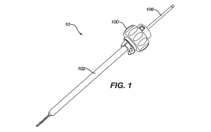
[0006] Fig. 1 shows a side view of a depth gauge system according to an
exemplary embodiment
of the present disclosure;
[0007] Fig. 2 shows a side view of the depth gauge of the system of Fig. 1
according to an
exemplary embodiment;
[0008] Fig. 3 shows a perspective view of the depth gauge of the system of
Fig. 1;
[0009] Fig. 4 shows a cross-sectional view of the system of Fig. 1;
[0010] Fig. 5 shows the path of an infrared light beam emitted by the light
source of the system
of Fig. 1 according to an exemplary embodiment;
[0011] Fig. 6 shows two exemplary frames captured by an image sensor of the
system of Fig. 1
according to an exemplary embodiment; and
[0012] Fig. 7 shows a graph of the acceleration pattern of a drill of the
system of Fig. 1 passing
through a long bone.
Detailed Description
[0013] The present disclosure may be understood with reference to the
following description and
the appended drawings, wherein like elements are referred to with the same
reference numerals.
The present disclosure relates to a method and device for measuring the
required length of a bone
4
CA 03071335 2020-01-28
WO 2019/030624
PCT/IB2018/055825
screw using an infrared laser diode. In an exemplary embodiment, the measuring
device
includes an adjustable universal clamp interface for mounting the device on a
drill sleeve or soft
tissue protection sleeve. Those skilled in the art will appreciate that the
principles of the
invention apply to any distance measurement that may be necessary in a patient
during a surgical
procedure. It should be noted that the terms "proximal" and "distal" as used
herein are intended
to refer to a direction toward (proximal) and away from (distal) a user of the
device.
[0014] Figure 1 illustrates an exemplary depth measuring system 10 including a
depth gauge
device 100 positioned on a protection sleeve 102 during a surgical procedure
to measure drill-bit
linear movement (depth) through a bone 104 within the patient's body. For
example, during an
operation, the device 100 may be used to measure the movement of a drill-bit
106 extending
through the depth gauge device 100 and the protection sleeve 102. The depth
gauge device 100,
as shown in Figs. 2-4, includes a depth gauge body 108, an adjustable clamp
110 with a clamp
adjustment mechanism 112 and an infrared (IR) laser imaging system 114. The
body 108
extends from a proximal end 116 to a distal end 118 and includes a channel 120
extending
therethrough. In this embodiment, the channel 120 is substantially cylindrical
in shape and
adapted for insertion of the drill-bit 106 therethrough. However, it will be
understood that the
channel 120 may be any shape suitable for insertion of a drill-bit 106. The
body 108 includes, in
this embodiment, a mounting portion 122 open to the channel 120 for mounting
of the IR laser
imaging system 114. The mounting portion 122 may be, for example, a hollowed
space within
the body 108. In another embodiment, the channel 120 may include a lateral
cutout (not shown)
within the wall of the channel 120 into the body 108 so that the IR imaging
system 114 may be
mounted within the cutout without protruding into the channel 120 or coming
into contact with
the drill-bit 106. In the present embodiment, the mounting portion 122 is open
to the channel
120 via a light-passing hole 124 in the channel 120 wall. The light-passing
hole 124 is sized and
shaped for the passing of a first light beam 148 from the light source 142
within the mounting
portion 122 and a second incident light beam 154 reflected off of the surface
150 of the drill-bit
106 to the image sensor 144 (as discussed in further detail below). The light-
passing hole 124
protects the light source 142 from detecting any outside light other than the
second incident light
5
CA 03071335 2020-01-28
WO 2019/030624
PCT/IB2018/055825
beam 154.
[0015] In an exemplary embodiment, the depth gauge body 108 includes an
adjustable universal
clamp 110, including an adjustment mechanism 112, coupled to the distal end
118. The clamp
110 may include a plurality of arms 128 extending from a proximal end 130
coupled to the body
108 to a free distal end 132 adapted for clamping the device 100 to the
protection sleeve 102, as
can be seen in Figs. 3-4. The proximal ends 130 of the clamp arms 128 are
distributed about a
circumference of the distal end of the body 108 to provide stable engagement
between the device
100 and the protection sleeve 102. In an embodiment, the distal ends 132 of
the arms 128
include a hook feature 134 to hook about a head 136 of the protection sleeve
102. However, it
will be understood that the distal ends 132 may be shaped in any way that
provides a stable
clamp connection between the device 100 and the protection sleeve 102. The
arms 128 may be
tightened about the protection sleeve 102 via rotation of the clamp adjustment
mechanism 112.
The clamp adjustment mechanism 112 comprises a rotating member 138 coupled to
the arms 128
for adjustment thereof. For example, in this embodiment rotation of the
rotating member 138 in
a first direction moves the arms 120 inwardly toward the central longitudinal
axis, L, of the
device 100 while rotation of the rotating member 138 in a second opposing
direction moves the
arms 128 outwardly away from the longitudinal axis. Thus, the clamp 110 can be
adjusted to
size of the protection sleeve 102 to which it is being coupled. In this
embodiment, the clamp
adjustment mechanism 112 is disposed about the outer circumference of the body
108.
However, it will be understood that the adjustment mechanism 112 may be
positioned anywhere
on the body 108 so long as rotation of the adjustment mechanism 112
facilitates movement of the
arms 128 as described. As shown in Fig. 3, the adjustment mechanism 112 may
include
markings 140 indicating a protection sleeve diameter around which the clamp
110 will fit when
the adjustment mechanism 112 is aligned with a specified marking 140. As
shown, in this
embodiment, the body 102 includes markings 140 numbered at 0.5 intervals
(indicating the size
of the drill bit to be used), but any type of marking at any interval
indicating the varying
sizes is sufficient.
6
CA 03071335 2020-01-28
WO 2019/030624
PCT/IB2018/055825
[0016] The IR laser imaging system 114, as shown in Figs. 4-5, is mounted
within the mounting
portion 122 of the body 108. The imaging system 114 uses digital image
correlation to
determine relative position between the device 100 and the drill-bit 106,
which may be in motion
(as represented by arrows 164, 166) in any direction in a two-dimensional
plane relative to the
device 100. The imaging system 114 includes a light source 142, an image
sensor 144 and a
processing unit 146 all of which are, in this embodiment, mounted inside the
body 108. In an
exemplary embodiment, the light source 142 provides an infrared (IR) laser
beam 148 to increase
the resolution of images taken by the image sensor 144 and thus, more
accurately measure the
depth of holes drilled. In the present embodiment, an IR laser beam 148 is
directed linearly from
the light source 142 through the light-passing hole 124 directly to the
surface 150 of the drill-bit
106 and a surface image 152 is then generated from the incident light 154
reflected from the
drill-bit surface 150. However, it will be understood by those skilled in the
art that the IR
imaging system 114 may include one or more interfaces (not shown) to reflect
and direct the IR
laser beam 148 along a specified path to or from the drill-bit surface 150 so
long as the incident
light reflected by the drill-bit surface 150 generates a surface image. In
this embodiment, the IR
laser beam 148 travels at an incident angle of, for example, about 45 degrees
from the light
source 142. However, any incident angle may be used to direct the IR laser
beam 148 to the
drill-bit surface 150. The light source 142 may be any infrared laser, such as
an infrared laser
diode, emitting an infrared light beam.
[0017] The image sensor 144 is also mounted in the mounting portion 122 and
includes image
sensing cells (not shown) facing the drill-bit surface 150 for sensing the
reflected incident laser
beam 154 from the drill-bit surface 150 and generating a detected image 152.
As would be
understood by those skilled in the art, existing sensors are capable of taking
more than 12,000
frames per second (fps), with a resolution up to 12,000 dots per inch (dpi)
and may sense
acceleration of up to 40G, and speeds up to 7 meters per second (m/s). In the
present
embodiment, the image sensor captures up to 12000 successive frames or more
per second. The
image sensor 144 images the naturally occurring texture in the material of the
drill-bit 106 so that
no gradations or markings are necessary on the drill bit 106.
7
CA 03071335 2020-01-28
WO 2019/030624
PCT/IB2018/055825
[0018] The processing unit 146 is coupled to the image sensor 144 to generate
electrical signals
from the detected images 152 generated by the image sensor 144. Specifically,
in this
embodiment, the image sensor 144 takes successive images of the drill-bit
surface 150. This
surface 150, when lit at a grazing angle by the light source 142, casts
distinct shadows that
resemble hilly terrain. Images 152 of these surface features are captured in
succession and
compared to each other to determine an amount of movement of the drill bit
represented by the
differences between successive images. The processing unit 146 processes these
images 152
using cross correlation to calculate an offset between successive image in
both the x-direction
and the y-directions. For example, the processing unit 146 may detect drill-
bit axial translation
as well as rotational motion. By comparing successive stored images 152a,
152b, as represented
in Fig. 6, relative motion can be determined such that a correlation
calculation of the patterns
within the images 152a, 152b can be used to determine the distance and
direction of the
movement represented by the difference between the successive images. For
example, a first
captured image overlaps partially with a prior captured imaged so that a
single portion of the drill
bit is represented in both images. Thus, software algorithms of the processing
unit 146 may
look, for example, at specific identifiable points in each image 152 and then
calculate the
distance and direction of the relative movement by noting the movement of such
identifiable
points. Depending on how fast the drill-bit 106 is moving, each image 152a,
152b may be offset
from the previous one by a fraction of a pixel or as many as several pixels.
By storing successive
image pairs, these characteristics that "overlap" can be identified, yielding
direction and
magnitude of translation in both the x-direction and the y-direction. In the
present embodiment,
the detected rotational movement of the drill-bit 106 is discarded and only
linear translation up
and down (y-direction) is recorded by the processing unit 146. However, in
another
embodiment, the rotational movement (x-direction) of the drill-bit 106 may
also be stored for
informational purposes. In an embodiment, the processing unit 146 may be
coupled to a display
screen 156 located on the device 100 for displaying the recorded linear
movement (depth). In an
exemplary embodiment, the processing unit 146 includes network communication
capabilities
such as Wi-Fi or Bluetooth through which the device 100 may be connected to,
for example, a
8
CA 03071335 2020-01-28
WO 2019/030624
PCT/IB2018/055825
computer device or a power-driven drilling tool (for example to trigger the
power-tool off
when passing the second cortex).
[0019] In an embodiment, the device software may recognize the acceleration or
deceleration
patterns of the drill-bit to indicate what portion of the bone the drill-bit
106 is passing through.
For example, as can be seen in Fig. 7, a typical long bone 10 (i.e., femur or
tibia) includes a hard
outer-layer, cortical bone 160a, 160b (zones 1 and 3), and a softer inner core
of spongious bone
162 (zone 2). A drill bit entering the spongious core 162 will accelerate from
its speed in the
harder first cortex 160a, as shown in the graph of Fig. 7. Contrarily, the
drill-bit 106 will
decelerate when entering the second cortex 160b of the bone from the spongious
core 162. The
device software according to this embodiment detects and tracks these changes
in linear
acceleration to recognize and indicate to the user when the drill-bit 106 is
passing from one
portion of bone to another (e.g., exiting the spongious core 162 and entering
the second cortex
(zone 2) 160b (zone 3)). The indicator may be either audio or visual. For
example, in an
embodiment, the device 100 may provide an audible beep or ping when the drill-
bit 106 is
exiting the second cortex 106b. In another embodiment, the device 100 may
provide a visible
blinking light when the drill-bit 106 is exiting the second cortex 106b. This
indication signal
may prevent unnecessary drilling past the second cortex 106b and thus, prevent
unnecessary
trauma to surrounding tissue.
[0020] In use, the depth gauge device 100 is attached to the proximal end of a
protection sleeve
102. The clamp arms 128 are sized to the diameter of the protection sleeve
head 136 by rotation
of the adjustment mechanism 112. When the device 100 is attached to the
protection sleeve 102,
both the device 100 and the protection sleeve 102 are held stationary relative
to one another and
the target bone 104. The drill-bit 106 may then be inserted through the
central channel 120 and
the channel of the protection sleeve 102. When drilling begins, the light
source 142 projects an
IR laser beam 148 through the light-passing hole 124 and on to the drill-bit
surface 150. The
incident light beam 154 reflected from the drill-bit surface 150 to the image
sensor 144 is
captured in successive image frames 152 which are processed by the processing
unit 146 to
9
CA 03071335 2020-01-28
WO 2019/030624
PCT/IB2018/055825
calculate the linear motion of the drill-bit 106 relative to the depth gauge
device 100. The linear
movement may be displayed to the user on a display screen 156 or otherwise
communicated to a
user. In an embodiment, the linear movement is updated in real time. In
another embodiment,
the linear movement is provided after drilling has been completed.
[0021] It will be appreciated by those skilled in the art that changes may be
made to the
embodiments described above without departing from the inventive concept
thereof. It should be
further appreciated that structural features and method associated with one of
the embodiments
can be incorporated into other embodiments. It is understood, therefore, that
this invention is not
limited to the particular embodiments discloses, but rather modifications are
also covered within
the scope of the present invention as defined by the appended claims.