Note: Descriptions are shown in the official language in which they were submitted.
CA 03071555 2020-01-29
WO 2019/032507 PCT/US2018/045499
FLEXIBLE GLASS RUN PROFILE WITH MULTIPLE MATERIALS FOR DIFFERENT
FUNCTIONAL BENEFITS
Background
[0001] The application claims the priority benefit of US provisional
application
Serial No. 62/542,072, filed August 7, 2017, the entire disclosure of which is
expressly
incorporated herein by reference.
[0002] This application is directed to a weatherstrip or weatherseal, and
more
particularly to a glass run such as used in an automotive vehicle.
[0003] A common cross-sectional construction or profile of a glass run is
a U-
shaped body having a base portion with first and second walls or legs
extending from
ends of the base portion to collectively define a cavity that receives an edge
of a
window. Typically, first and second seal lips extend from outer ends of the
first and
second legs, respectively, where the seal lips extend into the cavity for
sealing
engagement with opposite faces of the window.
[0004] Early glass run profiles were a single durometer material. As
profiles
increased in complexity, different materials were incorporated into the body
where the
goal was to improve installation. That is, prior arrangements typically used a
soft
material in the hinge area, conducive to folding for purposes of installation,
and capable
of opening and flexing to accommodate desired positioning of the seal lips
relative to
the window surfaces when installed in the automotive vehicle.
[0005] It has been generally taught to use different materials in the
glass run
profile, for example coextruding different portions of the glass run profile
from different
materials; however, the prior emphasis has primarily centered on forming the
seal lips of
a first material and forming the U-shaped body of a different, second
material.
Alternatively, or additionally, those surfaces of the seal lips that contact
the window are
sometimes coated (e.g., co-extrusion) with a material that has low friction or
good
sliding qualities.
[0006] Another issue relating to use of multiple materials such as a co-
extruded
assembly is that the interface between the different materials can adversely
impact the
1
CA 03071555 2020-01-29
WO 2019/032507 PCT/US2018/045499
aesthetics of the final assembly. Specifically, knit lines formed between
adjacent,
different materials are undesirable.
[0007] Analysis of the functional aspects of the glass run profile
illustrate that a
key to a high-quality seal relates to the hinge area formed at the interface
of the legs
with the seal lips. Generally, it is believed that the effectiveness of the
seal lips primarily
relates to the operation of the hinge, and the profile and material of the
seal lips is
secondary. Consequently, a need exists for a glass run assembly that focuses
on these
attributes in a manner that is flexible, durable, and highly functional in
design and that
addresses manufacturability, complexity, effectiveness and functionality in a
cost-
efficient manner.
Summary
[0008] A flexible glass run is provided that uses multiple materials to
address
different functional benefits.
[0009] A preferred glass run includes a body having a generally U-shaped
conformation that includes a base portion, and first and second legs extending
from the
base portion to define a cavity. First and second seal lips extend from the
first and
second legs, respectively. First and second hinges are interposed between the
first leg
and first seal lip, and the second leg and second seal lip, respectively. The
hinges are
formed of a first material different than a second material of the seal lips
where the first
material has high elasticity, and low compression set properties.
[0010] The body is formed of a different, third material than the first
material of
the hinges.
[0011] A coating is received over at least portions of the first and
second seal lips
that face the associated window edge.
[0012] The coating preferably extends over first and second junctions
formed
between the first and second seal lips and the first and second hinges in
order to cover
a transition between the first and second materials.
2
CA 03071555 2020-01-29
WO 2019/032507 PCT/US2018/045499
[0013] The first material extends over distal ends of the first and
second legs in
order to cover a transition between the first and third materials i.e.,
between the hinges
and the body (legs).
[0014] A preferred arrangement has a high elasticity, low compression
set, first
material, the second material is a low durometer material, and the third
material is a
high durometer, dense or microdense material.
[0015] In one preferred arrangement, the first material has a Shore
hardness of
about 55A to about 75A, the second material has a Shore hardness of about 55A
to
about 75A, and the third material has a Shore hardness of about 70A to about
45D.
[0016] A method of forming a glass run assembly includes forming a
generally U-
shaped body that includes a base portion and first and second legs extending
from the
base portion to define a cavity. The method further includes providing first
and second
seal lips that extend from the first and second legs, respectively, and
incorporating a
first hinge between the first leg and first seal lip, and a second hinge
between the
second leg and second seal lip, respectively, where the first and second
hinges are
formed of a first material different than a second material of the seal lips,
and the first
material has high elasticity and low compression set properties.
[0017] The method can preferably include covering an interface of the
first and
second hinges with the first and second seal lips, respectively.
[0018] Further, the method may include forming the first and second
hinges on
outer ends of the first and second legs of the body to cover an interface
therebetween.
[0019] A primary benefit is the ability to use desired materials at
preselected
locations in the profile of the glass run in order to provide different
functional benefits.
[0020] Another advantage resides in the ability to minimize cost of
manufacture
while providing desired performance characteristics.
[0021] Still another feature is that the performance of seal lips are
associated
with the high performance material used for the hinges, and thereby allow the
seal lips
to be formed of a less expensive material without any loss in functionality,
and similarly
the body of the glass run can be formed a less expensive material, i.e., due
to the
3
CA 03071555 2020-01-29
WO 2019/032507 PCT/US2018/045499
importance of the hinge portions with respect to sealing performance, the
hinge portions
are formed of a more expensive material and the overall cost of the glass run
assembly
is cost effective due to limiting the higher cost material to the hinge
portions only.
[0022] Other benefits and advantages of the present disclosure will
become more
apparent from reading and understanding the following detailed description.
Brief Description of the Drawings
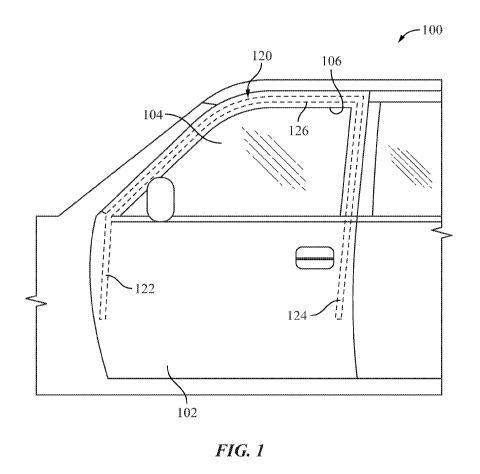
[0023] Figure 1 shows a door of an automotive vehicle.
[0024] Figure 2 is a cross-sectional illustration of a finite element
analysis
undertaken on a glass run.
[0025] Figure 3 is a cross-sectional view of a portion of the glass run
of the
present disclosure.
Detailed Description
[0026] Turning to Figure 1, a portion of an automotive vehicle 100 is
illustrated,
and more particularly an automotive door 102 that includes a movable window
104 that
is selectively raised and lowered relative to an opening 106 in the door. A
weatherstrip
assembly such as a glass run assembly (or sometimes referred to as a glass
run) 120 is
mounted to the door 102. The weatherstrip assembly described and shown herein
is
representative of and likewise could also refer to and be used in connection
with other
vehicle weatherstrips or seals such as a belt seal, cutline seal, etc., used
on an
automotive vehicle that seals between adjacent vehicle surfaces. One skilled
in the art
will recognize how the features of the present disclosure could be used in
alternative
weatherstrips. The glass run 120 includes first and second pillar portions
122, 124 that
extend in a generally vertical direction from header portion 126. The first
and second
pillar portions 122, 124 receive vertical edges of the window 104 as the
window is
raised and lowered relative to the window opening 106 in the door, while the
header
portion 126 of the glass run 120 receives an upper edge of the window when the
window is in the raised position.
4
CA 03071555 2020-01-29
WO 2019/032507 PCT/US2018/045499
[0027] Figure 2 is a cross-sectional representation of the strains
imposed on the
glass run 120. Specifically, a conventional glass run 120 has a generally U-
shaped
body 130 that includes a base portion 132 and first and second sidewalls or
legs 134,
136 that extend outwardly from opposite edges of the base portion. The U-
shaped body
130 forms an internal cavity 138 that receives an edge of the window 104. In a
manner
well known in the art, the door 102 includes a structure forming a cavity 140
that
receives the glass run 120. Legs 134, 136 of the glass run 120 preferably
include at
least one seal lip, namely first seal lip 144, and second seal lip 146
extending from the
first leg 134 and the second leg 136, respectively, at a location spaced from
the base
portion 132. The seal lips 144, 146, and an additional or third seal lip 148
provided on
the second leg 136, for example, are connected to the first and second legs
134, 136
via respective hinges 154, 156, 158. The seal lips 144, 146, 148 extend
inwardly into
the cavity 138 of the glass run 120 so that surfaces of the seal lips are
contoured and
the hinges urge the surfaces of the seal lips that face the window 104 to
slidingly and
sealingly engage opposite faces of the window. In some instances, a coating
(e.g., a
low friction coating) 160, 162, 164 is provided on the window engaging
surfaces of the
respective seal lips 144, 146, 148 that face and selectively engage the
opposite
surfaces of the window 104.
[0028] As illustrated in Figure 2, different strains are imposed on the
material of
the glass run 120 that forms the body 130 (base portion 132, first and second
legs 134,
136, and first, second, and third hinges 154, 156, 158) and the first, second,
and third
seal lips 144, 146, 148 during engagement with the window 104. This analysis
(e.g.,
finite element analysis or FEA) evidences that the hinges 154, 156, 158 carry
the bulk of
the strain, i.e., are the areas of high strain, and that the energy or force
is transferred
through the seal lips 144, 146, 148 at the hinges 154, 156, 158.
[0029] In the past, a glass run was typically formed of a single
durometer
material. Subsequent developments began to use different materials at
different
locations (i.e., throughout the cross-sectional profile) of the glass run. For
example, the
industry generally preferred to use a harder material for the U-shaped body of
the glass
run while the seal lips were formed of a softer material. This manufacture
typically
made the hinges of the softer material used to form the seal lips and softer
than the
CA 03071555 2020-01-29
WO 2019/032507 PCT/US2018/045499
hard material of the U-shaped body that included the base and legs, because a
common method of manufacture and assembly was to extrude or coextrude the
glass
run profile. As a part of that manufacturing process, the softer material used
at the
hinge allowed the legs of the glass run to be deployed from a splayed or open
orientation and easily fold for mounting the glass run in the channel of the
door, and
thereby secure the glass run to the door. Thus, it was common to either
manufacture
the entire cross-sectional profile (base portion, legs, hinges, seal lips,
etc.) of a single
material, or alternatively manufacture the entire seal lip and hinge from the
same, softer
material and manufacture the body of the hard material.
[0030] The present disclosure, however, uniquely forms only the hinge
areas
154, 156, 158 of a high elasticity, low compression set, functional material.
The term
"functional" is intended to generally mean portions or areas of the assembly
where the
strains are high and important or necessary to the seal function of the glass
run 120.
This functional material is a higher cost and thus it would not be
contemplated to use
the higher cost material for the entire cross-section or for major portions
thereof since
the overall cost of the glass run 120 would undesirably increase. As shown and
described in this disclosure, using the higher cost, higher elasticity, lower
compression
set material only in those areas (i.e., seal lip hinge areas 154, 156, 158)
where the
desired engineered value is needed, obtains an improved glass run 120 that
advantageously and judiciously (i.e., carefully and sparingly) uses this more
expensive
material in select areas only of the glass run profile where the value is
needed, and that
results in a glass run that is practical, efficient, and cost effective.
[0031] More specifically, and with reference to Figure 3, like reference
numerals
in the "200" series will be used to describe like components for purposes of
brevity and
understanding (e.g., in Figure 1, the glass run was referenced as 120 and in
Figure 3
the glass run will be referred to as 220). The generally U-shaped body 230
includes
base portion 232 and first and second legs 234, 236. Each of the base portion
232 and
the legs 234, 236 is preferably formed of a low-cost, high durometer, non-
functional
dense or microdense material, for example having a hardness of about 75 Shore
A
hardness to about 45 Shore D hardness (also referred to herein as the third
material).
An exemplary material that meets these parameters in association with the
6
CA 03071555 2020-01-29
WO 2019/032507 PCT/US2018/045499
embodiments of Figures 2 or 3 includes thermoplastic and thermoset elastomers
such
as EPDM and TPE, or another equivalent material that meets these desired
parameters.
[0032] Each leg 234, 236 is interconnected to the base portion 232 with a
low-
cost, low durometer, non-functional material, for example possibly a dense or
microdense material having a hardness of about 55 to about 75 Shore A hardness
(also
referred to herein as the second material). An exemplary material that meets
these
parameters is TPE or EPDM rubber or an equivalent material that meets these
desired
parameters.
[0033] In addition, the seal lips 244, 246 are also preferably formed of
the low-
cost, low durometer, non-functional material, for example possibly a dense or
microdense material having a hardness of about 55 to about 75 Shore A
hardness.
Although it need not be the same material as is used to interconnect the base
portion
and legs, the seal lips could be formed of the same material, and is most
notable
because it need not be a highly functional material.
[0034] The hinges 254, 256 interposed between the respective first and
second
legs 234, 236 and the first and second seal lips 244, 246 are preferably a
high elasticity,
low compression set, functional material having a hardness of about 55 to
about 75
Shore A hardness (also referred to herein as the first material). An exemplary
material
that meets these parameters is an EPDM rubber, a TPE, or equivalent material
that
meets these desired specifications. The material used to form the hinges 254,
256 is
substantially more expensive than those materials that form the remainder of
the cross-
sectional profile of the glass run 220. It is evident that the high
elasticity, low
compression set material is used in that area of the hinges 254, 256 subject
to
increased flexure and increased forces of the glass run 220 (those hinge areas
as
illustrated and encircled in Figure 2).
[0035] Being formed of a highly functional material, it will be
appreciated,
therefore, that due to the increased cost, the amount of this material used in
the profile
will be minimized. Thus, even though there is a general desire to minimize the
amount
of this material used in the cross-section profile of the glass run due to
cost, this
7
CA 03071555 2020-01-29
WO 2019/032507 PCT/US2018/045499
material that forms the hinges 254, 256 also advantageously extends over an
entirety of
a distal end of each of the first and second legs 234, 236. The distal end of
each leg
234, 236 is that portion of the legs spaced furthest from the base portion
232. In this
manner, and in part for aesthetic reasons, the material that forms the hinges
254, 256
entirely covers the distal end of the first and second legs 234, 236 so that
the transitions
(knit lines) between the different materials forming the legs and the hinges
254, 256 are
not evident, i.e., the interfaces between the legs and the hinges is
completely covered
by the hinge material. It is for this reason that the material extends into
the region
denoted by reference numerals 254a, 256a even though the functionality of the
material
is not required in these regions.
[0036] Similarly, the interface/knit lines 254b, 256b between the hinges
254, 256
and the seal lips 244, 246, respectively, would otherwise be evident and
detract from
the aesthetics. However, the low friction coating 260, 262 on the first and
second seal
lips 244, 246, respectively covers the interface/knit line 254b, 256b between
the low-
cost material of the seal lips and the high cost material of the hinges 254,
256. Thus,
the low friction coating 260, 262 extends over those surfaces of the seal lips
244, 246
that are designed for sliding, sealing engagement with opposite surfaces of
the window
204 in a manner similar to that of the conventional glass run of Figure 1.
Further, low
friction coating 264, 266, 268 is preferably provided along select regions of
the first and
second legs 234, 236 and the base portion 232 that are designed for engagement
with
the window 204. A preferred material for the coextruded low friction coating
or slip coat
260, 262, 264, 266, 268 is silicone impregnated TPE or an equivalent material
that
satisfies the material parameters.
[0037] It will also be appreciated that interconnecting regions 270, 272
that
connect the base portion 232 with the respective legs 234, 236 may be formed
of the
same material that is used to form the legs, or could be a softer material
such as used
to form the seal lips 244, 246.
[0038] This written description uses examples to describe the disclosure,
including the best mode, and also to enable any person skilled in the art to
make and
use the disclosure. The patentable scope of the disclosure is defined by the
claims, and
8
CA 03071555 2020-01-29
WO 2019/032507 PCT/US2018/045499
may include other examples that occur to those skilled in the art. Such other
examples
are intended to be within the scope of the claims if they have structural
elements that do
not differ from the literal language of the claims, or if they include
equivalent structural
elements with insubstantial differences from the literal language of the
claims. For
example, other vehicle weatherstrip or seal applications may employ the
features and
make use of the advantages achieved with the present disclosure (e.g., in a
belt seal,
or outline seal) or a greater or lesser number of seal lips could be used in
various
applications without departing from the scope and intent of the present
disclosure.
Moreover, this disclosure is intended to seek protection for a combination of
components and/or steps and a combination of claims as originally presented
for
examination, as well as seek potential protection for other combinations of
components
and/or steps and combinations of claims during prosecution.
9