Note: Descriptions are shown in the official language in which they were submitted.
1
IMPROVED MEDICAL DEVICE WITH RESILIENTLY RETRACTING
SAFETY NEEDLE
The present invention relates to a medical device as
defined herein.
Many medical devices for percutaneous or venous
access for administering fluids to a patient or withdrawing
them from one are known. Examples of these medical devices
are micro infusion needles, fistula needles and catheter
needles.
Medical devices of this type comprise a rigid
component having a free cutting end, usually a metal
cannula, attached to a first end of a cannula holder. The
latter is inserted into a body of the device and has a
second end to which a (plastics) tube is attached, through
which the fluid administered to the patient or drawn
therefrom flows. The tube (and a connector connected to
it) allows body fluids to be transferred to and from
suitable accessories, for example, test tubes for sampling
under vacuum.
The cannula passes through the patient's skin and
places the other components of the device, which are
usually of plastics, in fluid communication with the
sampling or infusion site.
In some of these devices, for example, in fistula and
micro infusion needles, there are very flexible plastics
components (such as soft plastics wings) which help the
cannula to be properly and easily inserted into the
injection site. Normally the flexible wings are associated
with the body of the device and can be joined together in
a vertical position to aid insertion of the cannula into
the patient.
Wings are also provided with a specific surface
Date recue / Date received 2021-12-02
GA 03071621 2020-01-30
WO 2019/053568
PCT/IB2018/056808
2
finish which makes it easier for them to be gripped, and
improves the ability of the skin to transpire when these
wings, which are wider than the cannula, are attached to
the patient by means of suitable removable attachment
elements.
With these devices there is the problem associated
with possible contact between the cannula (cutting at the
tip) and a health operator after the device has been used
in the patient. This may give rise to the transmission of
infectious diseases, including very serious and
debilitating ones, such as, for example, AIDS and types
of viral hepatitis. For this reason, medical devices of
the above-mentioned type provided with safety systems to
prevent accidental punctures are known.
For example, the use of a tubular protective body in
sufficiently rigid plastics material which is manually
moved forward over the cannula after use into an
immobilising position protecting the tip of the metal
cannula is known. These systems are classified as being
of the active type (because they use a specific operation
in addition to the normal procedure of using the device
to activate the safety).
Other devices provide that movement of the plastics
protection body or, vice versa, retraction of the cannula
is brought about by a suitable automatic system which can
deliberately be activated by the user. Often these
systems use a preloaded resilient element such as a
resilient compression or tension spring as a motor for
the movement.
One such device provided with a safety system is
described in EP1306097. This known solution provides for
a projecting flexible arm on the cannula holder which
emerges from an opening in the body of the device when
3
the latter is in a position in which the cannula is
inserted into the patient's body. This arm has one end
close to the cannula holder in the form of a step which
bears against an edge of the opening of the body of the
device.
The cannula holder experiences the thrust of a
compression spring that tends to move the cannula holder
into the body of the device. This movement is however
impeded by the joint action of the step end of the above-
mentioned projecting flexible arm so that, as a result of
suitably shaped means, it is pressed in a direction at
right angles to the axis of the cannula towards the
interior or said aperture. In this case the step end is
pressed into the body of the device, separating itself
from the edge of the opening, thus enabling the spring to
displace the cannula holder within the body of the device
with consequent total re-entry of the cannula within said
body.
A similar solution is described in W02016007438.
Although offering protection for the health operator
using the medical device, these known solutions have a
disadvantage linked to the fact that re-entry of the
cannula into the body of the device can be activated in an
undesired and accidental way, and this can give rise to
obvious problems when the cannula is being introduced into
the patient's body or at any other time when this action
is unintentional.
The object of the present invention is to provide a
medical device with a resiliently retracting safety needle
that is improved in comparison with corresponding known
solutions.
According to a broad aspect, there is provided a
medical device for percutaneous or venous access for
Date Recue/Date Received 2021-09-08
3a
administering a fluid to a patient or sampling from the
patient, comprising a tubular body from which there
projects a cannula supported at a distal end of a cannula
holder, a proximal end of said cannula holder being
attached to a tube configured to circulate said fluid,
said cannula holder being configured to move within said
body of the medical device under a force of a resilient
thrust element; a stop member of one piece with said body
and configured to impede said movement of the cannula
holder being provided and activating means being provided
to allow such movement associated with the body of the
medical device acting together with activating counter-
means of one piece with said cannula holder; wherein said
cannula holder has a yielding part positioned between and
coaxially joined to its said distal end and to said
proximal end, whereby said yielding part is in fluid
communication with said distal end and with said proximal
end, said yielding part being configured to allow said
cannula holder, at the proximal end, to flex within the
body of the medical device when said activating means are
activated so as to separate said cannula holder from said
stop member to allow axial movement of the cannula holder
in the body of the medical device and disappearing
retraction of the cannula needle into this body.
Other possible aspect(s), object(s), embodiment(s),
variant(s) and/or advantage(s) of the present invention,
all being preferred and/or optional, are briefly
summarized hereinbelow.
For instance, an object of the invention is to provide
a medical device of the type indicated which is ____________________
Date Recue/Date Received 2021-09-08
CA 03071621 2020-01-30
WO 2019/053568
PCT/IB2018/056808
4
easy and safe to use, making it possible to avoid
accidental retraction of the needle during normal use.
Another object is to offer a medical device of the
above-mentioned type which ensures complete and stable
retraction of the cannula within the body of the device,
at the same time making it impossible for it to
subsequently emerge from that body and prcviding absolute
protection against accidental contacts between such
needle or cannula and a user or health operator.
Another object is that of providing a device of the
type mentioned which is ergonomic and easy to hold and
intuitive to use.
A further object is to provide a device of the
above-mentioned type which is compact, of solid
75 construction and free from any parts which are difficult
to construct and/or which may suffer possible and likely
deformation and breakage during transport or storage
throughout the service life of the device.
Another object is to provide a device of the above-
mentioned type which does not give rise to any problems
for the patient or causes body fluids to splash during
retraction during the stage when the needle or cannula is
withdrawn into the body of the device.
These and other objects which will be apparent to
those skilled in the art are accomplished by a medical
device according to the appended claims.
For a better understanding of the present invention
the following drawings are attached merely by way of a
non-limiting example, in which:
Figure 1 shows a perspective view of a device
according to the invention before it is used in a
patient;
Figure 2 shows a cross-section along the line 2-2 in
CA 03071621 2020-01-30
WO 2019/053568 PCT/IB2018/056808
-
Figure 1;
Figure 3 shows a perspective view of a component of
the device in Figure 1;
Figure 4 shows a cross-section along the line 4-4 in
Figure 3;
Figures 5A-53 and 5C show side views of variants of
the component in Figure 3;
Figure 6 shows a perspective view of another
component of the device in Figure 1 from one side;
Figure 7 shows a cross-section along the line 7-7 in
Figure 6;
Figure 8 shows a perspective view of another
component of the device according to the invention;
Figure 9 shows a cross-section along the line 9-9 in
Figure 8;
Figure 10 shows a perspective view of a further
component of the device according to the invention;
Figure 11 shows a cross-section along the line 11-11
in Figure 10;
Figure 12 shows a perspective view of the device in
Figure 1 after use;
Figures 13A, 13B and 13C show various stages in the
re-entry of a cannula of the device within the body of
the latter, the device being shown in longitudinal cross-
section in the various figures;
Figure 14 shows a perspective view of the device in
Figure 1 from one side;
Figures 15 and 16 respectively show a variant of the
device according to the invention, in longitudinal cross-
section, in position of use and after such use;
Figure 17 shows a perspective view of one component
of the variant of the device in Figures 15 and 16;
Figures 18, 19 and 20 show longitudinal cross-
CA 03071621 2020-01-30
WO 2019/053568
PCT/IB2018/056808
6
sectional views of different variants of the device
according to the invention in the position of use;
Figure 21 shows a perspective view of a further
variant of the device according to the invention;
Figure 22 shows a perspective view of a component of
the device in Figure 21;
Figures 23A and 23B show longitudinal cross-sections
of the device in Figure 21 during use with a patient and
after such use respectively;
Figure 24 shows a perspective view of a further
embodiment of a device according to the invention;
Figure 25 shows an exploded perspective view of one
component of the device in Figure 24;
Figure 26 shows a cross-section along the line 26-26
75 in Figure 25;
Figures 27 and 28 show longitudinal cross-sectional
views of the device in Figure 24 in a stage when it is
ready for use with a patient and in a stage after such
use, respectively;
Figure 29 shows a longitudinal cross-section of one
variant of part of the device according to the invention;
Figure 30 shows the part in Figure 29 in perspective
view from another angle and in longitudinal cross-
section;
Figure 31 shows a cross-section along the line 31-31
in Figure 29; and
Figures 32 and 33 show a perspective view and a
lateral view respectively of longitudinal cross-sections
of the terminal portion of the device according to the
invention, where the part shown in Figure 29 is present.
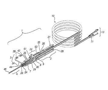
With reference to the figures mentioned, a medical
device according to the invention is generically
indicated by 1 and comprises a tubular body 2 acting
CA 03071621 2020-01-30
WO 2019/053568
PCT/IB2018/056808
7
together with wings 3 (which can be separated from body 2
or are of one piece with such body) and from which there
projects a cannula 4 (at a first extremity 2A thereof).
When the device is not in use the latter is covered by a
removable protection element 5. As will be described,
cannula 4 can be retracted into body 2 after use.
In a manner which is in itself known, cannula 4 is
attached to a (distal) flat end portion 7 of a cannula
holder 8 (which can move in body 2 when the cannula
retracts) having a second (proximal) end or end portion 9
which is of one piece with a normal tube 10. At one free
end 11 of such tube 10 there is a connector 13 of the
Luer Lock type, which is in itself known.
Body 2 may in a first version be of one piece and
75 have a second end 2B, a clip-closure cover (not shown) to
prevent cannula holder 8 emerging from such second end 2B
when the cannula retracts into body 2. This cover may be
replaced by a suitable restriction or permanent
deformation in second end 2B obtained during assembly of
device 1 and after cannula holder 8 has been inserted
into body 2.
In the embodiment in the figures, body 2 is
constructed using two sleeves 20 and 21, that is a sleeve
20 which is internal (or, better, partly internal) to an
outer sleeve 21. On this body 2, and in particular
internal sleeve 20 projecting from outer sleeve 21, there
is a cursor 24 capable of activating the re-entry
movement of cannula 4 into body 2 (in the case in the
figures, into inner sleeve 20). This movement is brought
about by compression spring 26 located between the first
end 2A of inner sleeve 20 (from a hole 28 in which
cannula 4 emerges) and a collar 29 made on first end 7 of
cannula holder 8.
8
More particularly, wings 3 are made of soft plastics
(for example, soft PVC or TPE) and can be easily folded
back onto each other in a vertical position and can be
easily grasped thanks to projections (not shown and in
themselves known) present on an under surface 3A of the
wings. The wings remain paired thanks to suitable
protrusions 3B which insert into corresponding recesses 30
when the wings are vertical.
Figures 3 and 4 show inner sleeve 20 which is tubular
and comprises the protection for cannula 4 after it has
re-entered within body 20. Figures 5A-5C show some possible
variants of this inner sleeve.
Inner sleeve 20 is made of rigid plastics material
(for example, polycarbonate) and may also be transparent.
Inner sleeve 20 has an inner guide 30, preferably of
variable cross-section, close to first end 2A of that
sleeve. Guide 30 enables cannula holder 8 to retract in a
guided manner above all during the initial stage of the
movement. Inner sleeve 20 also has a window 31 having a
side 32 defined by an inclined plane. This inclined side
or plane 32 (acting as a member stopping the cannula
holder) projects into window or cavity 31 and interferes
with an immobilising tooth 35 of cannula holder 8, as will
be described. As may be seen from Figures 4, 10 and 11,
inclined plane or side 32 and the immobilising tooth act
together alternately to impede or allow activation and
retraction of cannula holder 8 following movement of cursor
24.
Inner sleeve 20 has a channel 36 close to second end
2B (coinciding with that of body 2) which with guide 30
enables cannula holder 8 to move back in line and prevents
it from rotating. In addition to this, sleeve 20 has
lateral guides 40 housing suitable projections 30 of
CA 3071621 2020-04-02
GA 03071621 2020-01-30
WO 2019/053568
PCT/IB2018/056808
9
cursor 24 and guiding them along body 2 and a shaped
frontal recess 41 to house a coupling member 42 for soft
plastics wings 4 in an orientated manner.
Finally, inner sleeve 20 has a cylindrical frontal
projection 44 capable of housing protected element 5 of
cannula 4 and ensuring that tip 4K of the cannula is
covered after the mechanism for withdrawal into body 2
(or the safety mechanism) has been activated with
consequent re-entry of the cannula into body 2, said
return mechanism incorporating spring 26.
Another groove 46 is provided in the embodiments in
Figures 4, 5B and 5C and facilitates assembly of the
cannula holder within sleeve 20.
Inner sleeve 20 also comprises a portion 47 of
75 cavity 34 which is of wider cross-section than the
remaining part of aforesaid cavity 34. In addition to
this, on the outside, inner sleeve 20 has an outer flange
or collar 49 and second end 2B is preferably of oval
cross-section to ensure correctly orientated assembly
with outer sleeve 21. The oval section can increase the
ergonomics of the device by aiding a secure and correctly
orientated grip on the body of the device in comparison
with a cylindrical cross-section.
Figures 6 and 7 show outer jacket 21 comprising a
tubular terminal portion 54 from which a lower extension
55 capable of closing off groove 46 of inner sleeve 20
projects. A hole 56 is provided in terminal portion 54
for the passage of tube 10, and shaped lateral holes 57
(as in portion 54) or shaped elements are provided on the
sides of portion 54 itself in order to assist grip on
device 1.
Sleeves 20 and 21 are coupled together and nested
through the insertion of outer collar 49 of sleeve 20
GA 03071621 2020-01-30
WO 2019/053568
PCT/IB2018/056808
into an annular recess 58 provided internally in terminal
portion 54 of outer sleeve 21. This coupling may
alternatively be constructed or strengthened using
welding (for example, thermal or ultrasound welding) or
5 by means of adhesive bonding, or any other known system.
Figures 8 and 9 show activation cursor 24 for the
"retraction mechanism" for cannula 4 in body 2 (that is,
in the example, into inner sleeve 20). This mechanism
comprises spring 26 and cannula holder 8 which because of
10 its shape (as will be described) and acting together with
said cursor 24, can take up a displaced position with
respect to first end 2A of body 2 (or inner sleeve 20) or
towards second end 2B of such body. In the latter
position cannula 4 is within the body and protected from
75 accidental contacts.
As illustrated, one possible configuration of the
cursor comprises a hemicylindrical (or substantially
hemicylindrical) body 60 which can be positioned and move
along inner sleeve 20. This body 60 has externally a
shaped projection 61 capable of receiving the finger of
an operator using device 1 and surface ribs 62 enabling
the operator to have a direct grip on the cursor.
Internally there is a protuberance 63 having an
inclined wall 65 which is capable of acting together with
immobilising tooth 35 of cannula holder 8. This joint
action results in initial relative movement of cursor 24
over said tooth 35 without any immediate consequent
movement of cannula holder 8 in sleeve 20. It will be
noted that, as illustrated in Figures 10 and 11 in
particular, this immobilising tooth 35 has an inclined
wall 66 over which wall 65 of cursor 24 can move,
cooperation between said inclined walls 66 and 65
converting the axial displacement force of the cursor on
GA 03071621 2020-01-30
WO 2019/053568
PCT/IB2018/056808
11
sleeve 20 into a vertical component which detaches such
immobilising tooth 35 from inclined side 32 of sleeve 20
(acting as the stop member for body 2 capable of
preventing movement of cannula holder 8 until it is
required). As described above, before immobilising tooth
35 is released, cursor 24 has to travel a few
millimetres, which together with the joint action of the
inclined planes, the materials used and the friction
obtained help to reduce the risk of accidental activation
(because accidental contact with the cursor would make it
difficult to cause activation of the retraction
mechanism), while at the same time maintaining easy and
comfortable activation. It will be noted that the problem
of accidental activation is frequent in known medical
75 devices, in which it is only necessary to press the
button lightly to activate retraction; some known
solutions have attempted to eliminate this risk by, for
example, protection devices which have to be removed in
order to gain access to the button, but this has
introduced additional operations for the use which are
not very practical. One example of such known embodiments
is described in the prior art cited in the introductory
part of this text. It will be noted that activation of
the retraction mechanism is very intuitive and easy, in
that movement of cursor 24 takes place in the same
direction in which cannula 4 is extracted from the
patient's vein, reducing the difficulty perceived by the
user.
Figures 10 and 11 show cannula holder 8 which
ensures hydraulic continuity between cannula 4 and tube
10 and enables the cannula to remain exposed until the
user deliberately activates the retraction mechanism.
Cannula holder 8 comprises first (distal) part 7 and
GA 03071621 2020-01-30
WO 2019/053568
PCT/IB2018/056808
12
second part 9 (which is proximal with respect to tube
10).
Part 9 which is proximal to the tube is
characterised by a specific shape and incorporates
immobilising tooth 35 enabling rigid attachment to sleeve
20. The distal part of the tube comprises a housing 69
for the cannula and surface ribs 70 (possible ribs, but
these may or may not he present) capable of acting
together with spring 26 to hold the spring back, but
lo which are capable of moving without rotation within the
inner sleeve.
In the embodiment illustrated in the figures,
between distal part 7 and proximal part 9 there is a
yielding part 80 which permits relative movement between
75 distal part 7 and proximal part 9 of cannula holder 8. In
the figures this yielding part is illustrated as a
portion 80 of reduced cross-section ("thinned" or of
varied cross-section) capable of ensuring deformability
of cannula holder 8 and allowing rigid immobilising tooth
20 35 to move downwards under the action of cursor 24 within
portion 47 of cavity 34 of sleeve 20. Unlike known
solutions (for example, EP 1306097 and WO 2016007438), in
the present invention there is no resilient arm
projecting from the cannula holder, but it is a whole
25 portion of the cannula holder which moves downwards
within inner sleeve 20 so as to release rigid
immobilising tooth 35 (which is non-elastic and non-
resilient) under the force of cursor 24.
Yielding portion 80 may also be obtained by
30 constructing it as an area of different cross-section
from that of parts 7 and 8, through a portion obtained
from a yielding material which is in itself known or in
any other manner which permits relative movement between
GA 03071621 2020-01-30
WO 2019/053568
PCT/IB2018/056808
13
parts 7 and 9 of cannula holder 8.
In addition, and contrary to the known solutions
described above, activation of the retraction mechanism
does not take place through pressure in a radial
direction, directly on the flexible arm, or through the
interposition of a button which has to be pressed, but
occurs indirectly through cursor 24 (which runs with
sleeve 20).
The invention is used as follows: after sterile
device 1 has been removed from its container, if it is
not already present, connector 13 on tube 10 is connected
with a suitable accessory (which is in itself known, for
example, a syringe or connector for sampling under
vacuum) depending upon the medical procedure being
75 engaged in. Wings 3 are folded, and protected element 5
is removed, preventing damage to tip 4K of cannula 4
before use. Metal cannula 4 is Inserted into a vein or
into another suitable site depending upon the medical
procedure engaged in and the wings are released after
they have been positioned on the patient's skin and taped
with 5uitab1e medication to ntabilise the medical device
in the event of prolonged sampling/infusion. After the
fluids have been administered to and/or withdrawn from
the patient, and the stabilising device may have been
removed, a folded bandage (or equivalent) is positioned
on the injection site close to cannula 4 to prevent the
release of body fluids following retraction of the
cannula. The retraction mechanism is activated through
moving cursor 24 axially along body 2, in a linear
movement parallel to longitudinal axis K of the cannula.
This brings about initial displacement of protuberance or
projection 63 of cursor 24 towards inclined wall 66 of
cannula holder 8 (see Figure 13A), but this displacement
CA 03071621 2020-01-30
WO 2019/053568
PCT/IB2018/056808
14
of a few millimetres does not give rise to any thrust
force on immobilising tooth 35 of cannula holder 8 itself
and therefore such tooth does not move with respect to
inclined side 32 of first sleeve 20 of body 2 of the
device.
Continuing with the movement, protuberance 63 slides
on wall 66 of tooth 35 and begins to press that tooth and
distal portion 9 of cannula holder S. This movement of
the cursor then causes cannula holder 8 to bend in its
portion of reduced or different cross-section 80 (as
previously described) (which acts as a "hinge" between
distal portion 7 and proximal portion 8 of the cannula
holder), bending which causes immobilising tooth 35 to
detach from inclined side 32 (see Figure 13B).
At this point, as there is no stop to the movement
of cannula holder 8, spring 26 presses such cannula
holder 8 towards end 2B of body 2 causing tip 4K of
cannula 4 to retract and disappear into body 2 of the
device. Furthermore (see Figure 14), cannula holder 8 is
completely within body 2 (see Figure 13C).
Thanks to groove 36, proximal portion 9 of the
cannula holder is displaced from the K axis, stably
folding itself within body 2.
It is known that, as usual, spring 26 has the task
of storing the resilient energy necessary for generating
a force which when released through deliberate activation
is such that it fully retracts cannula 4 into inner
sleeve 20. However, spring 4 does not extend completely
as a result of activation and therefore helps to hold
cannula holder 8 within inner sleeve 20 and prevent the
tip 4K of the cannula from being exposed following
accidental impacts which, in the invention described
here, can only act on the tube, which being flexible can
GA 03071621 2020-01-30
WO 2019/053568
PCT/IB2018/056808
compensate for the effects of the impact without
generating translational movement of the cannula holder.
In the known solutions mentioned above (EP 1306097 and WO
2016007438) the rigid cannula holder projects from the
5 rear of the body of the device after activation and it is
therefore necessary to use resilient immobilising means
to prevent the cannula from again being exposed following
accidental impacts which might act on this rigid part
which is inherently unable to compensate for any
10 deformation.
Figure 15 and 16 show a variant of the invention in
which body 2 has a closure element 90 for end 2B; said
element comprises a body 91 with an open annular portion
92 which engages end 2B of body 2 and with a projecting
75 portion 93 having a part 94 capable of coming into
contact with cannula holder 8 when retracted into body 2
of the device. This part 94 is wedge-shaped so as to move
proximal end 9 of the cannula holder in a direction at
right angles to it. This causes immobilising tooth 35 to
project from an opening 97 made in end 2B of body 2 when
cannula holder 8 reaches the end of its travel. This
provides evidence that cannula 4 has safely re-entered
body 2, that is, the retraction mechanism of device 1 has
been correctly activated.
In this position, the cannula holder can no longer
be made to enter body 2.
In Figures 18-20, device 1 (always connected to a
tube 10 which is inherently not part of the inventive
device) provides for the use of braking members 100
associated with cannula holder 8 in Figure 18, an
elastomer ring being inserted into portion 80 of reduced
cross-section of the cannula holder. During retraction
this ring touches inner wall 101 of sleeve 20, slowing
GA 03071621 2020-01-30
WO 2019/053568
PCT/IB2018/056808
16
the movement of cannula holder 8.
In Figure 19, the elastomer ring is replaced by a
foam ring (made of or soaked with a material or substance
having high viscosity/viscoelasticity such as, for
example, high viscosity silicone grease); in Figure 20,
this ring is replaced by braking wings of deformable
plastics material. The action of the wings in combination
with wall 101 provides a braking effect, this effect
being greater at the start of the cannula holder's
movement when the wings deform against wall 101 of sleeve
following movement of proximal end 9 of cannula holder
8 pushed by cursor 24 into such sleeve.
Figures 21-23B show a further variant of the
invention in which closure element 90 has a portion 93
75 constructed in a resiliently deformable manner: this
portion comprises a tongue 110 which is inclined with
respect to a base 111 and rises from such base with an
end 112. The resilient tongue presses proximal portion 9
of cannula holder 8 towards opening 97 in such a way that
20 the immobilising tooth (which may be coloured) can emerge
from it.
In addition, cursor 24 has an indicator 117 of the
direction of translational movement on body 2.
Figures 24-28 illustrate a further variant of the
invention.
In the figures, device 1 is optimised for automatic
or semi-manual assembly; such a device comprises body 2
divided into two portion 2W and 2X so as to make cannula
holder 8 more accessible for assembly tools (such as, for
example, shaped supports). The two portions of the body
2W and 2X are lined up and assembled axially using, for
example, a snap joint. This joint is defined by one end
120 of first part 2W (or distal portion of body 2) having
GA 03071621 2020-01-30
WO 2019/053568
PCT/IB2018/056808
17
at least one recess 121 capable of receiving an end 122
of the second part (or proximal portion of body 2 with
reference to tube 10) having a collar 123 capable of
making a snap connection with such recess 121 in order to
make the joint between parts 2W and 2X.
Proximal portion 2X of body 2 (of tubular shape,
like distal portion 2W) has an inner wall 125 from which
project one or more resilient arms 126 capable of acting
together with portion 80 of the cannula holder when the
latter is retracted within body 2 of the device in order
to prevent movement towards first end 2A of such body.
The resilient arms are inclined with respect to wall 125
and face second end 2B of body 2 and their immobilising
effect can be increased through the presence of an
75 opposing inclined plane 139 which displaces cannula
holder 9 towards arms 126.
If present, arms 126 also act as a brake on movement
of cannula holder 8 when the mechanism for retracting
cannula 4 in body 2 is activated.
Finally, proximal portion 2X has projections 130
projecting from wall 125 at end 2B of body 2 to block
retraction movement of the catheter holder under the
thrust of spring 26.
Figures 29-33 illustrate a further variant of the
invention. This variant is similar to that in Figures 24
and 29 and therein part 2X comprises a resilient arm 126
projecting from inner wall 125 substantially opposite to
inclined planes 150 and 151 again located on that inner
part 125. Arm 126 always acts as a member immobilising
the cannula holder when it is completely retracted within
body 2 and acts together with inclined planes 150 and 151
(rigid undeformable elements) to retain cannula holder 8
in an immobilised position when it is in the completely
CA 03071621 2020-01-30
WO 2019/053568
PCT/IB2018/056808
18
retracted position. The cooperation between said arm 126
and inclined planes 150 and 151 maximises the
immobilising effect of resilient arm 126.
Various embodiments of the invention have been
described. Yet others are possible in order to obtain a
medical device falling within the scope of the invention
defined by the following claims.