Note: Descriptions are shown in the official language in which they were submitted.
CA 03071691 2020-01-30
WO 2019/028083
PCT/US2018/044707
INJECTION FLUIDS COMPRISING AN ANIONIC SURFACTANT FOR
TREATING UNCONVENTIONAL FORMATIONS
CROSS REFERENCE TO RELATED APPLICATIONS
[0001] This application claims the benefit of priority to U.S. Provisional
Application 62/538,883, filed July 31, 2017, which is incorporated by
reference herein in
its entirety.
TECHNICAL FIELD
[0002] The present disclosure relates generally to unconventional reservoirs,
and
more specifically to using low particle size injection fluids for treating
unconventional
subterranean formations.
BACKGROUND
[0003] Wells in unconventional or "tight" formations typically undergo
multiple
fracture stages which are completed in series during fracturing operations. To
prop open
fractures during such operations, specific cocktails of injection fluid are
employed to
viscosify the injection fluid and help transport proppant to the far reaches
of the fracture,
thereby establishing a larger propped fracture network and increased
stimulated reservoir
volume.
[0004] Typical injection fluids can include over a dozen chemical components
.. which are mixed into a surface water, typically brackish or recycled
production water.
During fracturing operations (completions stage) of an unconventional
horizontal well, the
injection fluids with these additive chemicals are pumped down the well in
large quantities
(-10,000 bbls) and the injection fluid contacts the surfaces of the fracture
network (Figure
1A prior to fluid injection; Figure 1B during fluid injection). Current
injection fluids
contain dirty water, unfiltered surface water, and/or oil carry-over in
surface water. The
condition of the injection fluid is such that it can be unstable when exposed
to reservoir
conditions, such as high temperature, high formation brine salinity, high
divalent ion
concentrations, etc. The unstable injection fluid can cause a loss in well
productivity due
to formation damage (Figure 1C). The term "formation damage" in this context
is used to
refer to plugging off matrix permeability (which can be on the order of 100's
of nano-
1
CA 03071691 2020-01-30
WO 2019/028083
PCT/US2018/044707
Darcies) in the formation thus obstructing or hindering fluid flow, for
example, due to the
suspended particles in the injection fluid precipitating out of solution and
causing the
plugging.
[0005] Embodiments of the disclosure include compositions and methods that
stabilize the injection fluid when exposed to reservoir conditions, reducing
formation
damage and increasing the amount of hydrocarbon recovered.
SUMMARY
[0006] Described herein are methods for treating unconventional subterranean
formations with fluids. The methods described herein can comprise combining a
single-
phase liquid surfactant package comprising a primary surfactant with an
aqueous-based
injection fluid to form a low particle size injection fluid; and introducing
the low particle
size injection fluid into the unconventional subterranean formation. The
primary
surfactant can comprise an anionic surfactant comprising a hydrophobic tail
comprising
from 6 to 60 carbon atoms. The low particle size injection fluid can have a
maximum
particle size of less than 0.1 micrometers in diameter in particle size
distribution
measurements performed at a temperature and salinity of the unconventional
subterranean
formation.
[0007] In some embodiments, the low particle size injection fluid can further
comprise a proppant. In these embodiments, the maximum particle size of less
than 0.1
micrometers can be measured exclusive of the proppant.
[0008] In some embodiments, the primary surfactant can comprise from 10% to
90% by weight of the single-phase liquid surfactant package. The primary
surfactant can
comprise, for example a sulfonate, a disulfonate, a polysulfonate, a sulfate,
a disulfate, a
polysulfate, a sulfosuccinate, a disulfosuccinate, a polysulfosuccinate, a
carboxylate, a
dicarboxylate, a polycarboxylate, or any combination thereof In some examples,
the
primary surfactant can comprise a C10-C30 internal olefin sulfonate, a C10-C30
isomerized olefin sulfonate, a C10-C30 alfa olefin sulfonate, a C8-C30 alkyl
benzene
sulfonate (ABS), a sulfosuccinate surfactant, or any combination thereof In
some
examples, the primary surfactant can comprise a branched or unbranched C6-
C32:P0(0-
.. 65):E0(0-100)-carboxylate (e.g., a branched or unbranched C6-C30:P0(30-
40):E0(25-
35)-carboxylate, a branched or unbranched C6-C12:P0(30-40):E0(25-35)-
carboxylate, a
branched or unbranched C6-C30:E0(8-30)-carboxylate, or any combination
thereof). In
2
CA 03071691 2020-01-30
WO 2019/028083
PCT/US2018/044707
some examples, the primary surfactant can comprise a surfactant defined by the
formula
below
IV¨R2¨R3
wherein IV comprises a branched or unbranched, saturated or unsaturated,
cyclic or non-
.. cyclic, hydrophobic carbon chain having 6-32 carbon atoms and an oxygen
atom linking
IV and R2; R2 comprises an alkoxylated chain comprising at least one oxide
group selected
from the group consisting of ethylene oxide, propylene oxide, butylene oxide,
and
combinations thereof and R3 comprises a branched or unbranched hydrocarbon
chain
comprising 2-12 carbon atoms and from 2 to 5 carboxylate groups. In some
examples, the
primary surfactant can comprise a surfactant defined by the formula below
SO3M SO3M
0
R4
wherein R4 is a branched or unbranched, saturated or unsaturated, cyclic or
non-cyclic,
hydrophobic carbon chain having 6-32 carbon atoms; and M represents a
counterion (e.g.,
Nat, 10.
[0009] In some embodiments, the single-phase liquid surfactant package can
optionally further comprise one or more secondary surfactants. The one or more
secondary surfactants can comprise from 10% to 90% by weight of the single-
phase liquid
surfactant package. The one or more secondary surfactants can comprise one or
more
non-ionic surfactants, one or more additional anionic surfactants, one or more
cationic
surfactants, one or more zwitterionic surfactants, or any combination thereof
In some
embodiments, the one or more secondary surfactants can comprise a non-ionic
surfactant.
In some examples, the non-ionic surfactant can comprise a branched or
unbranched C6-
C32:P0(0-65):E0(0-100) (e.g., a branched or unbranched C6-C30:P0(30-40):E0(25-
35),
a branched or unbranched C6-C12:P0(30-40):E0(25-35), a branched or unbranched
C6-
30:E0(8-30), or any combination thereof).
[0010] The aqueous-based injection fluid can comprise any type of water,
treated
or untreated, and can vary in salt content. For example, the aqueous-based
injection fluid
can comprise sea water, brackish water, fresh water, flowback or produced
water,
wastewater (e.g., reclaimed or recycled), river water, lake or pond water,
aquifer water,
brine (e.g., reservoir or synthetic brine), or any combination thereof In some
3
CA 03071691 2020-01-30
WO 2019/028083
PCT/US2018/044707
embodiments, the aqueous-based injection fluid can comprise slickwater.
100111 In some embodiments, the mean particle size distribution of the low
particle size injection fluid can be less than an average pore size of a rock
matrix in the
unconventional subterranean formation. In some embodiments, the mean particle
size
distribution of the low particle size injection fluid can be less than 0.05
micrometer in
diameter when measured at a temperature and salinity of the unconventional
subterranean
formation. In some embodiments, the aqueous-based injection fluid can have a
mean
particle size distribution of greater than 10 micrometers prior to the
addition of the single-
phase liquid surfactant package. In some embodiments, the mean particle size
distribution
of the low particle size injection fluid can be at least 10 p.m smaller than a
mean particle
size distribution of the aqueous-based injection fluid. In some embodiments,
the low
particle size injection fluid precipitates out fewer solid particles than the
aqueous-based
injection fluid when introduced into the rock matrix.
[0012] Combination of the single-phase liquid surfactant package with the
aqueous-based injection fluid can lower the particle size distribution of the
aqueous-based
injection fluid when measured at the temperature and salinity of the
unconventional
subterranean formation.
[0013] In some embodiments, the low particle size injection fluid can be
introduced at a wellhead pressure of from 0 PSI to 30,000 PSI (e.g., from
6,000 PSI to
30,000 PSI, or from 5,000 PSI to 10,000 PSI). The unconventional subterranean
formation can have a temperature of from 75 F to 350 F (e.g., from 150 F to
250 F), a
salinity of at least 5,000 ppm TDS (e.g., at least 100,000 ppm TDS, such as
from 100,000
ppm to 300,000 ppm TDS), a permeability of less than 25 mD (e.g., from 10 to
0.1
millidarcy (mD)), or any combination thereof
[0014] Optionally, the single-phase liquid surfactant package, the low
particle size
injection fluid, the aqueous-based injection fluid, or any combination thereof
can include
one or more additional components. For example, the single-phase liquid
surfactant
package, the low particle size injection fluid, the aqueous-based injection
fluid, or any
combination thereof can further comprise an acid, a polymer, a friction
reducer, a gelling
agent, a crosslinker, a scale inhibitor, a breaker, a pH adjusting agent, a
non-emulsifier
agent, an iron control agent, a corrosion inhibitor, a biocide, a clay
stabilizing agent, a
proppant, a wettability alteration chemical, a co-solvent (e.g., a Cl-05
alcohol, or an
alkoxylated Cl-05 alcohol), or any combination thereof In certain embodiments,
the
4
CA 03071691 2020-01-30
WO 2019/028083
PCT/US2018/044707
aqueous-based injection fluid can comprise an acid (e.g., at least 10% acid,
such as from
10% to 20% by weight acid).
[0015] Also provided are methods for treating an unconventional subterranean
formation with a fluid that comprise providing an aqueous-based injection
fluid for
treating the unconventional subterranean formation, the unconventional
subterranean
formation having a rock matrix with an average pore size less than 0.1
micrometer; and
adding an anionic surfactant to the aqueous-based injection fluid to form a
low particle
size injection fluid; and introducing the low particle size injection fluid
into the rock
matrix of the unconventional subterranean formation. The low particle size
injection fluid
can have a maximum particle size of less than 0.1 micrometer in diameter
particle size
distribution measurement when measured at a temperature and salinity of the
unconventional subterranean formation.
[0016] Also provided are methods for fracturing an unconventional subterranean
formation with a fluid. These methods can comprise combining a single-phase
liquid
surfactant package comprising a primary surfactant with an aqueous-based
injection fluid
to form a low particle size injection fluid; and injecting the low particle
size injection fluid
through a wellbore and into the unconventional subterranean formation at a
sufficient
pressure and at a sufficient rate to fracture the unconventional subterranean
formation.
The primary surfactant can comprise an anionic surfactant comprising a
hydrophobic tail
comprising from 6 to 60 carbon atoms. The low particle size injection fluid
can have a
maximum particle size of less than 0.1 micrometers in diameter in particle
size distribution
measurements performed at a temperature and salinity of the unconventional
subterranean
formation.
[0017] The wellbore can comprise a vertical trajectory, a horizontal
trajectory, or
any combination thereof In some embodiments, the method can comprise
performing a
fracturing operation on a region of the unconventional subterranean formation
proximate
to a new wellbore. In some embodiments, the method can comprise performing a
fracturing operation on a region of the unconventional subterranean formation
proximate
to an existing wellbore. In some embodiments, the method can comprise
performing a
refracturing operation on a previously fractured region of the unconventional
subterranean
formation proximate to a new wellbore. In some embodiments, the method can
comprise
performing a refracturing operation on a previously fractured region of the
unconventional
subterranean formation proximate to an existing wellbore. In some embodiments,
the
5
CA 03071691 2020-01-30
WO 2019/028083
PCT/US2018/044707
method can comprise performing a fracturing operation on a naturally fractured
region of
the unconventional subterranean formation proximate to a new wellbore. In some
embodiments, the method can comprise performing a fracturing operation on a
naturally
fractured region of the unconventional subterranean formation proximate to an
existing
wellbore.
BRIEF DESCRIPTION OF THE DRAWINGS
[0018] The drawings illustrate only example embodiments of methods, systems,
and devices for stabilizing injection fluids and are therefore not to be
considered limiting
of its scope, as aspects of the disclosure may admit to other equally
effective
embodiments. The elements and features shown in the drawings are not
necessarily to
scale, emphasis instead being placed upon clearly illustrating the principles
of the example
embodiments. Additionally, certain dimensions or positionings may be
exaggerated to
help visually convey such principles. In the drawings, reference numerals
designate like
or corresponding, but not necessarily identical, elements.
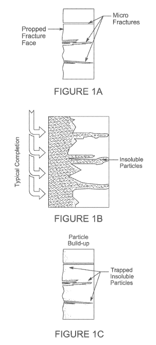
[0019] Figures 1A-1C illustrate some steps of a typical fracturing process
using
conventional injection fluids in an unconventional reservoir. Figure 1A shows
a portion of
the unconventional reservoir prior to injection of conventional injection
fluids. Figure 1B
illustrates conventional injection fluids being injected into the portion of
the
unconventional reservoir shown in Figure 1A. Figure 1C shows trapped particles
which
plug off matrix permeability in the portion of the unconventional reservoir,
left by
conventional injection fluids after the injection fluid is released from the
reservoir.
[0020] Figures 2A-2C illustrate injection of low particle size injection
fluids in a
portion of an unconventional reservoir. Figure 2A shows a portion of the
unconventional
reservoir prior to the injection of low particle size injection fluids. Figure
2B illustrates
the injection of low particle size injection fluids into the portion of the
unconventional
reservoir shown in Figure 2A where the insoluble particles are minimized and
the
chemicals penetrate the rock matrix. Figure 2C shows the unconventional
reservoir after
the low particle size injection fluid is released from the reservoir leaving
an increased
transmissibility and improved productivity compared to use of conventional
injection
fluids.
[0021] Figure 3A is a schematic illustration of methods of preparing low
particle
size injection fluids using the single-phase liquid surfactant packages
described herein.
6
CA 03071691 2020-01-30
WO 2019/028083
PCT/US2018/044707
The system includes a conventional surface blending system to accommodate the
preparation of low particle size injection fluids for use in a variety of
operations, including
fracturing operations (e.g., fracturing a formation that was not previously
fractured such as
hydraulically fracturing a formation for the first time) and refracturing
operations (e.g.,
fracturing a formation that was previously fractured such as hydraulically
fracturing a
formation a subsequent time). The system may also be used for completion of
new wells.
[0022] Figure 3B is a schematic illustration of alternative methods of
preparing
low particle size injection fluids using the single-phase liquid surfactant
packages
described herein. The system is simplified for use in the stimulation of a
fractured
formation with low particle size injection fluids (e.g., naturally fractured
formation or
formation that has undergone a fracturing operation or formation that has
undergone a
refracturing operation).
[0023] Figure 4 is a photograph of four containers with, from left to right,
slickwater and a single-phase liquid surfactant package (SPLC1), slickwater
and a second
single-phase liquid surfactant package (SPLC2), slickwater and a third single-
phase liquid
surfactant package (SPLC3), and slickwater only.
[0024] Figure 5 is a photograph of containers with increasing salinity over
background brine using slickwater and a single-phase liquid surfactant package
(SPLC1)
in, from left to right, SPLC1 only, +1% NaCl, +2.5% NaCl, +5% NaCl, +10% NaCl,
+15% NaCl, and slickwater only.
[0025] Figure 6 is a photograph of three containers comprising different
concentrations of a single-phase liquid surfactant package (SPLC1), from left
to right, 0.75
wt% SPLC1, 0.375 wt% SPLC1, and slickwater only tested at 75 C (167 F).
[0026] Figure 7 is a photograph of two containers, from left to right,
comprising a
mixture of a single-phase liquid surfactant package (SPLC1) and an injection
fluid
comprising sand at 75 C (167 F), and an injection fluid comprising sand only
tested at
75 C (167 F).
[0027] Figure 8 is the particle size distribution of slickwater only (solid
line) and
slickwater plus a C9-11 ethoxylated alcohol surfactant (dashed line), and
slickwater plus
benzenesulfonic acid, decyl(sulfophenoxy)-disodium salt (dotted line).
[0028] Figure 9 is the particle size distribution of slickwater only (solid
curved
line), slickwater plus benzenesulfonic acid, decyl(sulfophenoxy)-disodium salt
and a
Guerbet C10 ethoxylated alcohol surfactant (dotted straight line), and
slickwater plus
7
CA 03071691 2020-01-30
WO 2019/028083
PCT/US2018/044707
benzenesulfonic acid, decyl(sulfophenoxy)-disodium salt and a C9-11
ethoxylated alcohol
surfactant (dashed straight line having the same frequency value and being
coincident with
the dashed straight line for the version with the Guerbet non-ionic
surfactant).
[0029] Figure 10 is the particle size distribution of slickwater only (solid
curved
line), slickwater plus a Guerbet C10 ethoxylated alcohol surfactant (dashed
line), and
slickwater plus benzenesulfonic acid, decyl(sulfophenoxy)-disodium salt
surfactant
(dotted straight line).
[0030] Figure 11 is a photograph of three containers with, from left to right,
slickwater only, slickwater and a single-phase liquid surfactant package
(SPLC4), and
slickwater and internal olefin sulfonate (I0S).
[0031] Figure 12 is the particle size distribution of slickwater only (solid
curved
line), slickwater plus isomerized olefin sulfonate (I0S) and a Guerbet C10
ethoxylated
alcohol surfactant (dashed straight line), slickwater plus isomerized olefin
sulfonate
(dashed straight line having the same frequency value and being coincident
with the
dashed straight line for the version with the Guerbet non-ionic surfactant).
[0032] Figure 13 is an overlay profile of high-performance liquid
chromatography
(HPLC) for ethoxylated alcohol in deionized (DI) water and 15% hydrochloric
acid (HCL)
after being heated 3 days at 75 C (167 F).
[0033] Figure 14 a graph of fluid production at a tank battery level, which
encompasses five horizontal wells, four of which were stimulated using an
example LPS
injection fluid. The dots represent crude oil flow production and the solid
line represents a
decline curve extrapolation fit that was performed for the tank battery prior
to injection of
the LPS injection fluid.
[0034] Figure 15 shows tracer response curves for five horizontal wells, four
of
which were stimulated using an example LPS injection fluid. Injection fluid
for each well
was traced with a different chemical tracer in efforts to diagnose and
interpret fluid
production results. Tracer concentrations were measured from produced fluid
samples.
The quantity of tracer chemicals recovered compared to the total quantity
injected for the
comparison well with brine injection was much higher compared to the four
wells injected
with LPS fluid.
8
CA 03071691 2020-01-30
WO 2019/028083
PCT/US2018/044707
DETAILED DESCRIPTION OF EXAMPLE EMBODIMENTS
[0035] The example embodiments discussed herein are directed to compositions
and methods of stabilizing injection fluids.
[0036] As used in this specification and the following claims, the terms
"comprise" (as well as forms, derivatives, or variations thereof, such as
"comprising" and
"comprises") and "include" (as well as forms, derivatives, or variations
thereof, such as
"including" and "includes") are inclusive (i.e., open-ended) and do not
exclude additional
elements or steps. For example, the terms "comprise" and/or "comprising," when
used in
this specification, specify the presence of stated features, integers, steps,
operations,
elements, and/or components, but do not preclude the presence or addition of
one or more
other features, integers, steps, operations, elements, components, and/or
groups thereof
Accordingly, these terms are intended to not only cover the recited element(s)
or step(s),
but may also include other elements or steps not expressly recited.
Furthermore, as used
herein, the use of the terms "a" or "an" when used in conjunction with an
element may
mean "one," but it is also consistent with the meaning of "one or more," "at
least one,"
and "one or more than one." Therefore, an element preceded by "a" or "an" does
not,
without more constraints, preclude the existence of additional identical
elements.
[0037] The use of the term "about" applies to all numeric values, whether or
not
explicitly indicated. This term generally refers to a range of numbers that
one of ordinary
skill in the art would consider as a reasonable amount of deviation to the
recited numeric
values (i.e., having the equivalent function or result). For example, this
term can be
construed as including a deviation of 10 percent of the given numeric value
provided
such a deviation does not alter the end function or result of the value.
Therefore, a value
of about 1% can be construed to be a range from 0.9% to 1.1%. Furthermore, a
range may
be construed to include the start and the end of the range. For example, a
range of 10% to
20% (i.e., range of 10%-20%) can includes 10% and also includes 20%, and
includes
percentages in between 10% and 20%, unless explicitly stated otherwise herein.
[0038] It is understood that when combinations, subsets, groups, etc. of
elements
are disclosed (e.g., combinations of components in a composition, or
combinations of
steps in a method), that while specific reference of each of the various
individual and
collective combinations and permutations of these elements may not be
explicitly
disclosed, each is specifically contemplated and described herein. By way of
example, if
an item is described herein as including a component of type A, a component of
type B, a
9
CA 03071691 2020-01-30
WO 2019/028083
PCT/US2018/044707
component of type C, or any combination thereof, it is understood that this
phrase
describes all of the various individual and collective combinations and
permutations of
these components. For example, in some embodiments, the item described by this
phrase
could include only a component of type A. In some embodiments, the item
described by
this phrase could include only a component of type B. In some embodiments, the
item
described by this phrase could include only a component of type C. In some
embodiments, the item described by this phrase could include a component of
type A and
a component of type B. In some embodiments, the item described by this phrase
could
include a component of type A and a component of type C. In some embodiments,
the
item described by this phrase could include a component of type B and a
component of
type C. In some embodiments, the item described by this phrase could include a
component of type A, a component of type B, and a component of type C. In some
embodiments, the item described by this phrase could include two or more
components of
type A (e.g., Al and A2). In some embodiments, the item described by this
phrase could
include two or more components of type B (e.g., B1 and B2). In some
embodiments, the
item described by this phrase could include two or more components of type C
(e.g., Cl
and C2). In some embodiments, the item described by this phrase could include
two or
more of a first component (e.g., two or more components of type A (Al and
A2)),
optionally one or more of a second component (e.g., optionally one or more
components
of type B), and optionally one or more of a third component (e.g., optionally
one or more
components of type C). In some embodiments, the item described by this phrase
could
include two or more of a first component (e.g., two or more components of type
B (B1 and
B2)), optionally one or more of a second component (e.g., optionally one or
more
components of type A), and optionally one or more of a third component (e.g.,
optionally
one or more components of type C). In some embodiments, the item described by
this
phrase could include two or more of a first component (e.g., two or more
components of
type C (Cl and C2)), optionally one or more of a second component (e.g.,
optionally one
or more components of type A), and optionally one or more of a third component
(e.g.,
optionally one or more components of type B).
[0039] "Hydrocarbon-bearing formation" or simply "formation" refers to the
rock
matrix in which a wellbore may be drilled. For example, a formation refers to
a body of
rock that is sufficiently distinctive and continuous such that it can be
mapped. It should be
appreciated that while the term "formation" generally refers to geologic
formations of
CA 03071691 2020-01-30
WO 2019/028083
PCT/US2018/044707
interest, that the term "formation," as used herein, may, in some instances,
include any
geologic points or volumes of interest (such as a survey area).
[0040] "Unconventional formation" is a subterranean hydrocarbon-bearing
formation that requires intervention in order to recover hydrocarbons from the
reservoir at
economic flow rates or volumes. For example, an unconventional formation
includes
reservoirs having an unconventional microstructure, such as having submicron
pore size (a
rock matrix with an average pore size less than 1 micrometer), in which
fractures are used
to recover hydrocarbons from the reservoir at sufficient flow rates or volumes
(e.g., an
unconventional reservoir must be fractured under pressure or have naturally
occurring
fractures in order to recover hydrocarbons from the reservoir at sufficient
flow rates or
volumes).
[0041] In some embodiments, the unconventional formation can include a
reservoir having a permeability of less than 25 millidarcy (mD) (e.g., 20 mD
or less, 15
mD or less, 10 mD or less, 5 mD or less, 1 mD or less, 0.5 mD or less, 0.1 mD
or less,
0.05 mD or less, 0.01 mD or less, 0.005 mD or less, or 0.001 mD or less). In
some
embodiments, the unconventional formation can include a reservoir having a
permeability
of at least 0.001 mD (e.g., at least 0.005 mD, at least 0.01 mD, at least 0.05
mD, at least
0.1 mD, at least 0.5 mD, at least 1 mD, at least 5 mD, at least 10 mD, at
least 15 mD, or at
least 20 mD).
[0042] The unconventional formation can include a reservoir having a
permeability ranging from any of the minimum values described above to any of
the
maximum values described above. For example, in some embodiments, the
unconventional formation can include a reservoir having a permeability of from
0.001 mD
to 25 mD (e.g., from 0.001 mD to 10 mD, from 0.01 mD to 10 mD, from 0.1 mD to
10
mD, from 0.001 mD to 5 mD, from 0.01 mD to 5 mD, or from 0.1 mD to 5 mD).
[0043] The formation may include faults, fractures (e.g., naturally occurring
fractures, fractures created through hydraulic fracturing, etc.), geobodies,
overburdens,
underburdens, horizons, salts, salt welds, etc. The formation may be onshore,
offshore
(e.g., shallow water, deep water, etc.), etc. Furthermore, the formation may
include
hydrocarbons, such as liquid hydrocarbons (also known as oil or petroleum),
gas
hydrocarbons, a combination of liquid hydrocarbons and gas hydrocarbons (e.g.
including
gas condensate), etc.
11
CA 03071691 2020-01-30
WO 2019/028083
PCT/US2018/044707
[0044] The formation, the hydrocarbons, or both may also include non-
hydrocarbon items, such as pore space, connate water, brine, fluids from
enhanced oil
recovery, etc. The formation may also be divided up into one or more
hydrocarbon zones,
and hydrocarbons can be produced from each desired hydrocarbon zone.
[0045] The term formation may be used synonymously with the term reservoir.
For example, in some embodiments, the reservoir may be, but is not limited to,
a shale
reservoir, a carbonate reservoir, a tight sandstone reservoir, a tight
siltstone reservoir, a gas
hydrate reservoir, a coalbed methane reservoir, etc. Indeed, the terms
"formation,"
"reservoir," "hydrocarbon," and the like are not limited to any description or
configuration
described herein.
[0046] "Wellbore" refers to a continuous hole for use in hydrocarbon recovery,
including any openhole or uncased portion of the wellbore. For example, a
wellbore may
be a cylindrical hole drilled into the formation such that the wellbore is
surrounded by the
formation, including rocks, sands, sediments, etc. A wellbore may be used for
injection.
A wellbore may be used for production. A wellbore may be used for hydraulic
fracturing
of the formation. A wellbore even may be used for multiple purposes, such as
injection
and production. The wellbore may have vertical, inclined, horizontal, or a
combination of
trajectories. For example, the wellbore may be a vertical wellbore, a
horizontal wellbore,
a multilateral wellbore, or slanted wellbore. The wellbore may include a
"build section."
.. "Build section" refers to practically any section of a wellbore where the
deviation is
changing. As an example, the deviation is changing when the wellbore is
curving. The
wellbore may include a plurality of components, such as, but not limited to, a
casing, a
liner, a tubing string, a heating element, a sensor, a packer, a screen, a
gravel pack, etc.
The wellbore may also include equipment to control fluid flow into the
wellbore, control
fluid flow out of the wellbore, or any combination thereof For example, each
wellbore
may include a wellhead, a BOP, chokes, valves, or other control devices. These
control
devices may be located on the surface, under the surface (e.g., downhole in
the wellbore),
or any combination thereof The wellbore may also include at least one
artificial lift
device, such as, but not limited to, an electrical submersible pump (ESP) or
gas lift. Some
non-limiting examples of wellbores may be found in U.S. Patent Application
Publication
No. 2014/0288909 (Attorney Dkt. No. T-9407) and U.S. Patent Application
Publication
No. 2016/0281494A1 (Attorney Dkt. No. T-10089), each of which is incorporated
by
reference in its entirety. The term wellbore is not limited to any description
or
12
CA 03071691 2020-01-30
WO 2019/028083
PCT/US2018/044707
configuration described herein. The term wellbore may be used synonymously
with the
terms borehole or well.
[0047] "Single-phase liquid or fluid," as used herein, refers to a fluid which
only
has a single-phase, i.e. only a water phase. A single-phase fluid is not an
emulsion. A
single-phase fluid is in a thermodynamically stable state such that it does
not
macroscopically separate into distinct layers or precipitate out solid
particles. In some
embodiments, the single-phase liquid comprises a single-phase liquid
surfactant package
including one or more anionic and/or non-ionic surfactants.
[0048] "Aqueous stable," as used herein, refers to a solution whose soluble
components remain dissolved and is a single phase as opposed to precipitating
as
particulates or phase separating into 2 or more phases. As such, aqueous
stable solutions
are clear and transparent statically and when agitated. Conversely, solutions
may be
described as "aqueous unstable" when components precipitate from solution as
particulates or phase separates into 2 or more phases. The aqueous stability
of solutions
can be assessed by evaluating whether the Tyndall Effect (light scattering by
suspended
particulates) is observed when monochromatic light is directed through the
solution. If a
sample exhibits the Tyndall effect, the solution may be characterized as
"aqueous
unstable." Conversely, if a sample does not exhibit the Tyndall effect, the
solution may
be characterized as "aqueous stable."
[0049] "Slickwater," as used herein, refers to water-based injection fluid
comprising a friction reducer which is typically pumped at high rates to
fracture a
reservoir. Optionally when employing slickwater, smaller sized proppant
particles (e.g.,
40/70 or 50/140 mesh size) are used due to the fluid having a relatively low
viscosity (and
therefore a diminished ability to transport sizable proppants relative to more
viscous
fluids). In some embodiments, proppants are added to some stages of
completion/stimulation during production of an unconventional reservoir. In
some
embodiments, slickwater is injected with a small quantity of proppant.
[0050] "Friction reducer," as used herein, refers to a chemical additive that
alters
fluid rheological properties to reduce friction created within the fluid as it
flows through
small-diameter tubulars or similar restrictions (e.g., valves, pumps).
Generally polymers,
or similar friction reducing agents, add viscosity to the fluid, which reduces
the turbulence
induced as the fluid flows. Reductions in fluid friction of greater than 50%
are possible
depending on the friction reducer utilized, which allows the injection fluid
to be injected
13
CA 03071691 2020-01-30
WO 2019/028083
PCT/US2018/044707
into a wellbore at a much higher injection rate (e.g., between 60 to 100
barrels per minute)
and also lower pumping pressure during proppant injection.
[0051] "Injection fluid" or "LPS injection fluid," as used herein, refers to
any fluid
which is injected into a reservoir via a well. The injection fluid may include
one or more
of an acid, a polymer, a friction reducer, a gelling agent, a crosslinker, a
scale inhibitor, a
breaker, a pH adjusting agent, a non-emulsifier agent, an iron control agent,
a corrosion
inhibitor, a biocide, a clay stabilizing agent, a proppant, a wettability
alteration chemical, a
co-solvent (e.g., a Cl-05 alcohol, or an alkoxylated Cl-05 alcohol), or any
combination
thereof, to increase the efficacy of the injection fluid.
[0052] "Low particle size injection fluid" refers to an injection fluid having
a
maximum particle size of less than 0.1 micrometers in diameter in particle
size distribution
measurements performed at a temperature and salinity of the unconventional
formation for
which injection is to occur. For example, the low particle size injection
fluid can be
formed by mixing an aqueous-based injection fluid with a single-phase fluid
comprising a
single-phase liquid surfactant package. Prior to being dosed with the anionic
or non-ionic
surfactant to form the low particle size injection fluid, the aqueous based
fluid may have
been used as the injection fluid.
[0053] "Fracturing fluid," as used herein, refers to an injection fluid that
is injected
into the well under pressure in order to cause fracturing within a portion of
the reservoir.
[0054] The term "interfacial tension" or "IFT" as used herein refers to the
surface
tension between test oil and water of different salinities containing a
surfactant
formulation at different concentrations. Typically, interfacial tensions are
measured using
a spinning drop tensiometer or calculated from phase behavior experiments.
[0055] The term "proximate" is defined as "near". If item A is proximate to
item
B, then item A is near item B. For example, in some embodiments, item A may be
in
contact with item B. For example, in some embodiments, there may be at least
one barrier
between item A and item B such that item A and item B are near each other, but
not in
contact with each other. The barrier may be a fluid barrier, a non-fluid
barrier (e.g., a
structural barrier), or any combination thereof Both scenarios are
contemplated within
the meaning of the term "proximate."
[0056] Unless defined otherwise, all technical and scientific terms used
herein
have the same meanings as commonly understood by one of skill in the art to
which the
14
CA 03071691 2020-01-30
WO 2019/028083
PCT/US2018/044707
disclosed invention belongs. Unless otherwise specified, all percentages are
in weight
percent and the pressure is in atmospheres.
[0057] The compositions and methods described herein relate to compositions
and
methods described in PCT/ __________ , filed July 31, 2018 (Attorney Docket
No.
10467-028W01 (CVX Ref: T-10666B), filed July 31, 2018 entitled "Injection
Fluids
Comprising Non-Ionic Surfactants for Treating Unconventional Formations"); and
PCT/
______________ , filed July 31, 2018 (Attorney Docket No. 10467-030W01 (CVX
Ref: T-
10666C), filed July 31, 2018 entitled "Injection Fluids for Stimulating
Fractured
Formations"), all of which are hereby incorporated by reference.
COMPOSITIONS
[0058] An embodiment of the disclosure is a single-phase liquid surfactant
package which decreases the particle size distribution when combined with an
aqueous-
based injection fluid to create a low particle size (LPS) injection fluid. The
low particle
size injection fluid can have a maximum particle size of less than 0.1
micrometers in
diameter in particle size distribution measurements performed at a temperature
and salinity
of the unconventional subterranean formation. In specific embodiments, after
injection
into a reservoir, the LPS injection fluid retains the lowered particle size
distribution within
the reservoir. In certain embodiments, the LPS injection fluid lowers the
particle size
distribution of the reservoir fluid after being injected into the reservoir
and mixing with
the reservoir fluid. In embodiments, the aqueous-based injection fluid when
combined
with the single-phase liquid surfactant package maintains itself as a single-
phase, that is,
as the LPS injection fluid is pumped downhole it remains a homogenous single-
phase
solution within the reservoir, even when mixed with the native reservoir
fluid.
[0059] The single-phase liquid surfactant package can comprise a primary
surfactant and optionally one or more secondary surfactants. The primary
surfactant can
comprise an anionic surfactant. The one or more secondary surfactants can
comprise one
or more non-ionic surfactants, one or more additional anionic surfactants, one
or more
cationic surfactants, one or more zwitterionic surfactants, or any combination
thereof
[0060] In some embodiments, the primary surfactant can comprise at least 10%
by
weight (e.g., at least 15% by weight, at least 20% by weight, at least 25% by
weight, at
least 30% by weight, at least 35% by weight, at least 40% by weight, at least
45% by
weight, at least 50% by weight, at least 55% by weight, at least 60% by
weight, at least
CA 03071691 2020-01-30
WO 2019/028083
PCT/US2018/044707
65% by weight, at least 70% by weight, at least 75% by weight, at least 80% by
weight, or
at least 85% by weight) of the single-phase liquid surfactant package, based
on the total
weight of the single-phase liquid surfactant package. In some embodiments, the
primary
surfactant can comprise 90% by weight or less (e.g., 85% by weight or less,
80% by
weight or less, 75% by weight or less, 70% by weight or less, 65% by weight or
less, 60%
by weight or less, 55% by weight or less, 50% by weight or less, 45% by weight
or less,
40% by weight or less, 35% by weight or less, 30% by weight or less, 25% by
weight or
less, 20% by weight or less, or 15% by weight or less) of the single-phase
liquid surfactant
package, based on the total weight of the single-phase liquid surfactant
package.
[0061] The primary surfactant can be present in the single-phase liquid
surfactant
package in an amount ranging from any of the minimum values described above to
any of
the maximum values described above. For example, in some embodiments, the
primary
surfactant can comprise from 10% to 90% by weight (e.g., from 10% to 50% by
weight) of
the single-phase liquid surfactant package, based on the total weight of the
single-phase
liquid surfactant package.
[0062] In some embodiments, the one or more secondary surfactants can comprise
at least 10% by weight (e.g., at least 15% by weight, at least 20% by weight,
at least 25%
by weight, at least 30% by weight, at least 35% by weight, at least 40% by
weight, at least
45% by weight, at least 50% by weight, at least 55% by weight, at least 60% by
weight, at
least 65% by weight, at least 70% by weight, at least 75% by weight, at least
80% by
weight, or at least 85% by weight) of the single-phase liquid surfactant
package, based on
the total weight of the single-phase liquid surfactant package. In some
embodiments, the
one or more secondary surfactants can comprise 90% by weight or less (e.g.,
85% by
weight or less, 80% by weight or less, 75% by weight or less, 70% by weight or
less, 65%
by weight or less, 60% by weight or less, 55% by weight or less, 50% by weight
or less,
45% by weight or less, 40% by weight or less, 35% by weight or less, 30% by
weight or
less, 25% by weight or less, 20% by weight or less, or 15% by weight or less)
of the
single-phase liquid surfactant package, based on the total weight of the
single-phase liquid
surfactant package.
[0063] The one or more secondary surfactants can be present in the single-
phase
liquid surfactant package in an amount ranging from any of the minimum values
described
above to any of the maximum values described above. For example, in some
embodiments, the one or more secondary surfactants can comprise from 10% to
90% by
16
CA 03071691 2020-01-30
WO 2019/028083
PCT/US2018/044707
weight (e.g., from 10% to 50% by weight) of the single-phase liquid surfactant
package,
based on the total weight of the single-phase liquid surfactant package.
[0064] In some embodiments, the single-phase liquid surfactant package can
comprise an anionic surfactant. In other embodiments, the single-phase liquid
surfactant
package can consist essentially of an anionic surfactant (i.e., the anionic
surfactant is the
only surfactant present in the single-phase liquid surfactant package). In
other
embodiments, the single-phase liquid surfactant package can consist of an
anionic
surfactant. In some of these embodiments, the single-phase liquid surfactant
package
further includes water. In some of these embodiments, the single-phase liquid
surfactant
package does not comprise a hydrocarbon.
[0065] In some embodiments, the single-phase liquid surfactant package can
comprise an anionic surfactant and a non-ionic surfactant. In other
embodiments, the
single-phase liquid surfactant package can consist essentially of an anionic
surfactant and
a non-ionic surfactant (i.e., the anionic surfactant and the non-ionic
surfactant are the only
surfactants present in the single-phase liquid surfactant package). In other
embodiments,
the single-phase liquid surfactant package can consist of an anionic
surfactant and a non-
ionic surfactant. In some of these embodiments, the single-phase liquid
surfactant package
further includes water. In some of these embodiments, the single-phase liquid
surfactant
package does not comprise a hydrocarbon.
[0066] In some embodiments, the single-phase liquid surfactant package can
comprise an anionic surfactant, a second anionic surfactant, and a non-ionic
surfactant. In
other embodiments, the single-phase liquid surfactant package can consist
essentially of an
anionic surfactant, a second anionic surfactant, and a non-ionic surfactant
(i.e., the anionic
surfactant, the second anionic surfactant, and the non-ionic surfactant are
the only
surfactants present in the single-phase liquid surfactant package). In other
embodiments,
the single-phase liquid surfactant package can consist of an anionic
surfactant, a second
anionic surfactant, and a non-ionic surfactant. In some of these embodiments,
the single-
phase liquid surfactant package further includes water. In some of these
embodiments, the
single-phase liquid surfactant package does not comprise a hydrocarbon.
[0067] Suitable anionic surfactants for use as a primary surfactant and/or a
secondary surfactant include a hydrophobic tail that comprises from 6 to 60
carbon atoms.
In some embodiments, the anionic surfactant can include a hydrophobic tail
that comprises
at least 6 carbon atoms (e.g., at least 7 carbon atoms, at least 8 carbon
atoms, at least 9
17
CA 03071691 2020-01-30
WO 2019/028083
PCT/US2018/044707
carbon atoms, at least 10 carbon atoms, at least 11 carbon atoms, at least 12
carbon atoms,
at least 13 carbon atoms, at least 14 carbon atoms, at least 15 carbon atoms,
at least 16
carbon atoms, at least 17 carbon atoms, at least 18 carbon atoms, at least 19
carbon atoms,
at least 20 carbon atoms, at least 21 carbon atoms, at least 22 carbon atoms,
at least 23
carbon atoms, at least 24 carbon atoms, at least 25 carbon atoms, at least 26
carbon atoms,
at least 27 carbon atoms, at least 28 carbon atoms, at least 29 carbon atoms,
at least 30
carbon atoms, at least 31 carbon atoms, at least 32 carbon atoms, at least 33
carbon atoms,
at least 34 carbon atoms, at least 35 carbon atoms, at least 36 carbon atoms,
at least 37
carbon atoms, at least 38 carbon atoms, at least 39 carbon atoms, at least 40
carbon atoms,
at least 41 carbon atoms, at least 42 carbon atoms, at least 43 carbon atoms,
at least 44
carbon atoms, at least 45 carbon atoms, at least 46 carbon atoms, at least 47
carbon atoms,
at least 48 carbon atoms, at least 49 carbon atoms, at least 50 carbon atoms,
at least 51
carbon atoms, at least 52 carbon atoms, at least 53 carbon atoms, at least 54
carbon atoms,
at least 55 carbon atoms, at least 56 carbon atoms, at least 57 carbon atoms,
at least 58
carbon atoms, or at least 59 carbon atoms). In some embodiments, the anionic
surfactant
can include a hydrophobic tail that comprises 60 carbon atoms or less (e.g.,
59 carbon
atoms or less, 58 carbon atoms or less, 57 carbon atoms or less, 56 carbon
atoms or less,
55 carbon atoms or less, 54 carbon atoms or less, 53 carbon atoms or less, 52
carbon
atoms or less, 51 carbon atoms or less, 50 carbon atoms or less, 49 carbon
atoms or less,
48 carbon atoms or less, 47 carbon atoms or less, 46 carbon atoms or less, 45
carbon
atoms or less, 44 carbon atoms or less, 43 carbon atoms or less, 42 carbon
atoms or less,
41 carbon atoms or less, 40 carbon atoms or less, 39 carbon atoms or less, 38
carbon
atoms or less, 37 carbon atoms or less, 36 carbon atoms or less, 35 carbon
atoms or less,
34 carbon atoms or less, 33 carbon atoms or less, 32 carbon atoms or less, 31
carbon
atoms or less, 30 carbon atoms or less, 29 carbon atoms or less, 28 carbon
atoms or less,
27 carbon atoms or less, 26 carbon atoms or less, 25 carbon atoms or less, 24
carbon
atoms or less, 23 carbon atoms or less, 22 carbon atoms or less, 21 carbon
atoms or less,
20 carbon atoms or less, 19 carbon atoms or less, 18 carbon atoms or less, 17
carbon
atoms or less, 16 carbon atoms or less, 15 carbon atoms or less, 14 carbon
atoms or less,
13 carbon atoms or less, 12 carbon atoms or less, 11 carbon atoms or less, 10
carbon
atoms or less, 9 carbon atoms or less, 8 carbon atoms or less, or 7 carbon
atoms or less).
[0068] The anionic surfactant can include a hydrophobic tail that comprises a
number of carbon atoms ranging from any of the minimum values described above
to any
18
CA 03071691 2020-01-30
WO 2019/028083
PCT/US2018/044707
of the maximum values described above. For example, in some embodiments, the
anionic
surfactant can comprise a hydrophobic tail comprising from 6 to 15, from 16 to
30, from
31 to 45, from 46 to 60, from 6 to 25, from 26 to 60, from 6 to 30, from 31 to
60, from 6 to
32, from 33 to 60, from 6 to 12, from 13 to 22, from 23 to 32, from 33 to 42,
from 43 to
52, from 53 to 60, from 6 to 10, from 10 to 15, from 16 to 25, from 26 to 35,
or from 36 to
45 carbon atoms. The hydrophobic (lipophilic) carbon tail may be a straight
chain,
branched chain, and/or may comprise cyclic structures. The hydrophobic carbon
tail may
comprise single bonds, double bonds, triple bonds, or any combination thereof
In some
embodiments, the anionic surfactant can include a branched hydrophobic tail
derived from
Guerbet alcohols. The hydrophilic portion of the anionic surfactant can
comprise, for
example, one or more sulfate moieties (e.g., one, two, or three sulfate
moieties), one or
more sulfonate moieties (e.g., one, two, or three sulfonate moieties), one or
more
sulfosuccinate moieties (e.g., one, two, or three sulfosuccinate moieties),
one or more
carboxylate moieties (e.g., one, two, or three carboxylate moieties), or any
combination
thereof
[0069] In some embodiments, the anionic surfactant can comprise, for example a
sulfonate, a disulfonate, a polysulfonate, a sulfate, a disulfate, a
polysulfate, a
sulfosuccinate, a disulfosuccinate, a polysulfosuccinate, a carboxylate, a
dicarboxylate, a
polycarboxylate, or any combination thereof In some examples, the anionic
surfactant
can comprise an internal olefin sulfonate (I0S), an isomerized olefin
sulfonate, an alfa
olefin sulfonate (AOS), an alkyl aryl sulfonate (AAS), a xylene sulfonate, an
alkane
sulfonate, a petroleum sulfonate, an alkyl diphenyl oxide (di)sulfonate, an
alcohol sulfate,
an alkoxy sulfate, an alkoxy sulfonate, an alkoxy carboxylate, an alcohol
phosphate, or an
alkoxy phosphate. In some embodiments, the anionic surfactant can comprise an
alkoxy
carboxylate surfactant, an alkoxy sulfate surfactant, an alkoxy sulfonate
surfactant, an
alkyl sulfonate surfactant, an aryl sulfonate surfactant, or an olefin
sulfonate surfactant.
[0070] An "alkoxy carboxylate surfactant" or "alkoxy carboxylate" refers to a
compound having an alkyl or aryl attached to one or more alkoxylene groups
(typically ¨
CH2-CH(ethyl)-0-, ¨CH2-CH(methyl)-0-, or ¨CH2-CH2-0-) which, in turn is
attached to
¨COO- or acid or salt thereof including metal cations such as sodium. In
embodiments,
19
CA 03071691 2020-01-30
WO 2019/028083
PCT/US2018/044707
the alkoxy carboxylate surfactant can be defined by the formulae below:
\f )-0 \/
-( 0
R1-0 CH2-CH-OCH 18-0H R1-0 cH2-CH-0--cH '-c)- A4+
1 1 1 1
R2 , \R3
n z R2 jn\ R3 z
or
wherein Rl is substituted or unsubstituted C6-C36 alkyl or substituted or
unsubstituted aryl; R2 is, independently for each occurrence within the
compound,
hydrogen or unsubstituted C1-C6 alkyl; R3 is independently hydrogen or
unsubstituted
C1-C6 alkyl, n is an integer from 0 to 175, z is an integer from 1 to 6 and
WI+ is a
monovalent, divalent or trivalent cation. In some of these embodiments, Rl can
be an
unsubstituted linear or branched C6-C36 alkyl.
[0071] In certain embodiments, the alkoxy carboxylate can be a C6-C32:P0(0-
65):E0(0-100)-carboxylate (i.e., a C6-C32 hydrophobic tail, such as a branched
or
unbranched C6-C32 alkyl group, attached to from 0 to 65 propyleneoxy groups (-
CH2-
CH(methyl)-0- linkers), attached in turn to from 0 to 100 ethyleneoxy groups (-
CH2-CH2-0- linkers), attached in turn to -COO- or an acid or salt thereof
including metal
cations such as sodium). In certain embodiments, the alkoxy carboxylate can be
a
branched or unbranched C6-C30:P0(30-40):E0(25-35)-carboxylate. In certain
embodiments, the alkoxy carboxylate can be a branched or unbranched C6-
C12:P0(30-
40):E0(25-35)-carboxylate. In certain embodiments, the alkoxy carboxylate can
be a
branched or unbranched C6-C30:E0(8-30)-carboxylate.
[0072] An "alkoxy sulfate surfactant" or "alkoxy sulfate" refers to a
surfactant
having an alkyl or aryl attached to one or more alkoxylene groups (typically -
CH2-
CH(ethyl)-0-, -CH2-CH(methyl)-0-, or -CH2-CH2-0-) which, in turn is attached
to -S03-
or acid or salt thereof including metal cations such as sodium. In some
embodiment, the
alkoxy sulfate surfactant has the formula R-(B0)e-(PO)f-(E0)g-S03- or acid or
salt
(including metal cations such as sodium) thereof, wherein R is C6-C32 alkyl,
BO
is -CH2-CH(ethyl)-0-, PO is -CH2-CH(methyl)-0-, and EO is -CH2-CH2-0-. The
symbols e, f and g are integers from 0 to 50 wherein at least one is not zero.
[0073] In embodiments, the alkoxy sulfate surfactant can be an aryl alkoxy
sulfate
surfactant. The aryl alkoxy surfactant can be an alkoxy surfactant having an
aryl attached
to one or more alkoxylene groups (typically -CH2-CH(ethyl)-0-, -CH2-CH(methyl)-
0-,
or -CH2-CH2-0-) which, in turn is attached to -S03- or acid or salt thereof
including metal
cations such as sodium.
CA 03071691 2020-01-30
WO 2019/028083
PCT/US2018/044707
[0074] An "alkyl sulfonate surfactant" or "alkyl sulfonate" refers to a
compound
that includes an alkyl group (e.g., a branched or unbranched C6-C32 alkyl
group) attached
to -S03- or acid or salt thereof including metal cations such as sodium.
[0075] An "aryl sulfate surfactant" or "aryl sulfate" refers to a compound
having
an aryl group attached to -0-S03- or acid or salt thereof including metal
cations such as
sodium. An "aryl sulfonate surfactant" or "aryl sulfonate" refers to a
compound having an
aryl group attached to -S03- or acid or salt thereof including metal cations
such as sodium.
In some cases, the aryl group can be substituted, for example, with an alkyl
group (an
alkyl aryl sulfonate).
[0076] An "internal olefin sulfonate," "isomerized olefin sulfonate," or "IOS"
refers to an unsaturated hydrocarbon compound comprising at least one carbon-
carbon
double bond and at least one S03- group, or a salt thereof As used herein, a
"C20-
C28 internal olefin sulfonate," "a C20-C28 isomerized olefin sulfonate," or
"C20-C28
IOS" refers to an IOS, or a mixture of IOSs with an average carbon number of
20 to 28, or
of 23 to 25. The C20-C28 IOS may comprise at least 80% of IOS with carbon
numbers of
to 28, at least 90% of IOS with carbon numbers of 20 to 28, or at least 99% of
IOS with
carbon numbers of 20 to 28. As used herein, a "C15-C18 internal olefin
sulfonate," "C15-
C18 isomerized olefin sulfonate," or "C15-C18 IOS" refers to an IOS or a
mixture of IOSs
with an average carbon number of 15 to 18, or of 16 to 17. The C15-C18 105 may
20 comprise at least 80% of IOS with carbon numbers of 15 to 18, at least
90% of IOS with
carbon numbers of 15 to 18, or at least 99% of IOS with carbon numbers of 15
to 18. The
internal olefin sulfonates or isomerized olefin sulfonates may be alpha olefin
sulfonates,
such as an isomerized alpha olefin sulfonate. The internal olefin sulfonates
or isomerized
olefin sulfonates may also comprise branching. In certain embodiments, C15-18
IOS may
be added to the single-phase liquid surfactant package when the LPS injection
fluid is
intended for use in high temperature unconventional subterranean formations,
such as
formations above 130 F (approximately 55 C). The IOS may be at least 20%
branching,
30% branching, 40% branching, 50% branching, 60% branching, or 65% branching.
In
some embodiments, the branching is between 20-98%, 30-90%, 40-80%, or around
65%.
Examples of internal olefin sulfonates and the methods to make them are found
in U.S.
Pat. No. 5,488,148, U.S. Patent Application Publication 2009/0112014, and SPE
129766,
all incorporated herein by reference.
21
CA 03071691 2020-01-30
WO 2019/028083
PCT/US2018/044707
[0077] In embodiments, the anionic surfactant can be a disulfonate,
alkyldiphenyloxide disulfonate, mono alkyldiphenyloxide disulfonate, di
alkyldiphenyloxide disulfonate, or a di alkyldiphenyloxide monosulfonate,
where the alkyl
group can be a C6-C36 linear or branched alkyl group. In embodiments, the
anionic
.. surfactant can be an alkylbenzene sulfonate or a dibenzene disufonate. In
embodiments,
the anionic surfactant can be benzenesulfonic acid, decyl(sulfophenoxy)-
disodium salt;
linear or branched C6-C36 alkyl:P0(0-65):E0(0-100) sulfate; or linear or
branched C6-
C36 alkyl:P0(0-65):E0(0-100) carboxylate. In embodiments, the anionic
surfactant is an
isomerized olefin sulfonate (C6-C30), internal olefin sulfonate (C6-C30) or
internal olefin
disulfonate (C6-C30). In some embodiments, the anionic surfactant is a Guerbet-
P0(0-
65)-E0(0-100) sulfate (Guerbet portion can be C6-C36). In some embodiments,
the
anionic surfactant is a Guerbet-P0(0-65)-E0(0-100) carboxylate (Guerbet
portion can be
C6-C36). In some embodiments, the anionic surfactant is alkyl P0(0-65) and
E0(0-100)
sulfonate: where the alkyl group is linear or branched C6-C36. In some
embodiments, the
anionic surfactant is a sulfosuccinate, such as a dialkylsulfosuccinate. In
some
embodiments, the anionic surfactant is an alkyl aryl sulfonate (AAS) (e.g. an
alkyl
benzene sulfonate (ABS)), a C10-C30 internal olefin sulfate (I0S), a petroleum
sulfonate,
or an alkyl diphenyl oxide (di)sulfonate.
[0078] In some examples, the anionic surfactant can comprise a surfactant
defined
by the formula below:
R'¨R2--R3
wherein Rl comprises a branched or unbranched, saturated or unsaturated,
cyclic or
non-cyclic, hydrophobic carbon chain having 6-32 carbon atoms and an oxygen
atom
linking Rl and R2; R2 comprises an alkoxylated chain comprising at least one
oxide group
selected from the group consisting of ethylene oxide, propylene oxide,
butylene oxide, and
combinations thereof; and R3 comprises a branched or unbranched hydrocarbon
chain
comprising 2-12 carbon atoms and from 2 to 5 carboxylate groups.
[0079] In some examples, the anionic surfactant can comprise a surfactant
defined
by the formula below:
SO3M SO3M
se 0 41
R4
22
CA 03071691 2020-01-30
WO 2019/028083
PCT/US2018/044707
wherein IV is a branched or unbranched, saturated or unsaturated, cyclic or
non-
cyclic, hydrophobic carbon chain having 6-32 carbon atoms; and M represents a
counterion (e.g., Nat, ICE). In some embodiments, IV is a branched or
unbranched,
saturated or unsaturated, cyclic or non-cyclic, hydrophobic carbon chain
having 6-16
carbon atoms.
[0080] Suitable non-ionic surfactants for use as a secondary surfactant
include
compounds that can be added to increase wettability. In embodiments, the
hydrophilic-
lipophilic balance (HLB) of the non-ionic surfactant is greater than 10 (e.g.,
greater than 9,
greater than 8, or greater than 7). In some embodiments, the HLB of the non-
ionic
surfactant is from 7 to 10.
[0081] The non-ionic surfactant can comprise a hydrophobic tail comprising
from
6 to 60 carbon atoms. In some embodiments, the non-ionic surfactant can
include a
hydrophobic tail that comprises at least 6 carbon atoms (e.g., at least 7
carbon atoms, at
least 8 carbon atoms, at least 9 carbon atoms, at least 10 carbon atoms, at
least 11 carbon
atoms, at least 12 carbon atoms, at least 13 carbon atoms, at least 14 carbon
atoms, at least
15 carbon atoms, at least 16 carbon atoms, at least 17 carbon atoms, at least
18 carbon
atoms, at least 19 carbon atoms, at least 20 carbon atoms, at least 21 carbon
atoms, at least
22 carbon atoms, at least 23 carbon atoms, at least 24 carbon atoms, at least
25 carbon
atoms, at least 26 carbon atoms, at least 27 carbon atoms, at least 28 carbon
atoms, at least
29 carbon atoms, at least 30 carbon atoms, at least 31 carbon atoms, at least
32 carbon
atoms, at least 33 carbon atoms, at least 34 carbon atoms, at least 35 carbon
atoms, at least
36 carbon atoms, at least 37 carbon atoms, at least 38 carbon atoms, at least
39 carbon
atoms, at least 40 carbon atoms, at least 41 carbon atoms, at least 42 carbon
atoms, at least
43 carbon atoms, at least 44 carbon atoms, at least 45 carbon atoms, at least
46 carbon
atoms, at least 47 carbon atoms, at least 48 carbon atoms, at least 49 carbon
atoms, at least
50 carbon atoms, at least 51 carbon atoms, at least 52 carbon atoms, at least
53 carbon
atoms, at least 54 carbon atoms, at least 55 carbon atoms, at least 56 carbon
atoms, at least
57 carbon atoms, at least 58 carbon atoms, or at least 59 carbon atoms). In
some
embodiments, the non-ionic surfactant can include a hydrophobic tail that
comprises 60
carbon atoms or less (e.g., 59 carbon atoms or less, 58 carbon atoms or less,
57 carbon
atoms or less, 56 carbon atoms or less, 55 carbon atoms or less, 54 carbon
atoms or less,
53 carbon atoms or less, 52 carbon atoms or less, 51 carbon atoms or less, 50
carbon
atoms or less, 49 carbon atoms or less, 48 carbon atoms or less, 47 carbon
atoms or less,
23
CA 03071691 2020-01-30
WO 2019/028083
PCT/US2018/044707
46 carbon atoms or less, 45 carbon atoms or less, 44 carbon atoms or less, 43
carbon
atoms or less, 42 carbon atoms or less, 41 carbon atoms or less, 40 carbon
atoms or less,
39 carbon atoms or less, 38 carbon atoms or less, 37 carbon atoms or less, 36
carbon
atoms or less, 35 carbon atoms or less, 34 carbon atoms or less, 33 carbon
atoms or less,
32 carbon atoms or less, 31 carbon atoms or less, 30 carbon atoms or less, 29
carbon
atoms or less, 28 carbon atoms or less, 27 carbon atoms or less, 26 carbon
atoms or less,
25 carbon atoms or less, 24 carbon atoms or less, 23 carbon atoms or less, 22
carbon
atoms or less, 21 carbon atoms or less, 20 carbon atoms or less, 19 carbon
atoms or less,
18 carbon atoms or less, 17 carbon atoms or less, 16 carbon atoms or less, 15
carbon
atoms or less, 14 carbon atoms or less, 13 carbon atoms or less, 12 carbon
atoms or less,
11 carbon atoms or less, 10 carbon atoms or less, 9 carbon atoms or less, 8
carbon atoms
or less, or 7 carbon atoms or less).
[0082] The non-ionic surfactant can include a hydrophobic tail that comprises
a
number of carbon atoms ranging from any of the minimum values described above
to any
of the maximum values described above. For example, in some embodiments, the
non-
ionic surfactant can comprise a hydrophobic tail comprising from 6 to 15, from
16 to 30,
from 31 to 45, from 46 to 60, from 6 to 25, from 26 to 60, from 6 to 30, from
31 to 60,
from 6 to 32, from 33 to 60, from 6 to 12, from 13 to 22, from 23 to 32, from
33 to 42,
from 43 to 52, from 53 to 60, from 6 to 10, from 10 to 15, from 16 to 25, from
26 to 35, or
from 36 to 45 carbon atoms. In some cases, the hydrophobic tail may be a
straight chain,
branched chain, and/or may comprise cyclic structures. The hydrophobic carbon
tail may
comprise single bonds, double bonds, triple bonds, or any combination thereof
In some
cases, the hydrophobic tail can comprise an alkyl group, with or without an
aromatic ring
(e.g., a phenyl ring) attached to it. In some embodiments, the hydrophobic
tail can
comprise a branched hydrophobic tail derived from Guerbet alcohols.
[0083] Example non-ionic surfactants include alkyl aryl alkoxy alcohols, alkyl
alkoxy alcohols, or any combination thereof In embodiments, the non-ionic
surfactant
may be a mix of surfactants with different length lipophilic tail chain
lengths. For
example, the non-ionic surfactant may be C9-C11:9E0, which indicates a mixture
of non-
ionic surfactants that have a lipophilic tail length of 9 carbon to 11 carbon,
which is
followed by a chain of 9 E0s. The hydrophilic moiety is an alkyleneoxy chain
(e.g., an
ethoxy (EO), butoxy (BO) and/or propoxy (PO) chain with two or more repeating
units of
EO, BO, and/or PO). In some embodiments, 1-100 repeating units of EO are
present. In
24
CA 03071691 2020-01-30
WO 2019/028083
PCT/US2018/044707
some embodiments, 0-65 repeating units of PO are present. In some embodiments,
0-25
repeating units of BO are present. For example, the non-ionic surfactant could
comprise
10E0:5P0 or 5E0. In embodiments, the non-ionic surfactant may be a mix of
surfactants
with different length lipophilic tail chain lengths. For example, the non-
ionic surfactant
may be C9-C11:P09:E02, which indicates a mixture of non-ionic surfactants that
have a
lipophilic tail length of 9 carbon to 11 carbon, which is followed by a chain
of 9 POs and 2
E0s. In specific embodiments, the non-ionic surfactant is linear C9-C11:9E0.
In some
embodiments, the non-ionic surfactant is a Guerbet P0(0-65) and E0(0-100)
(Guerbet can
be C6-C36); or alkyl P0(0-65) and E0(0-100): where the alkyl group is linear
or branched
C1-C36. In some examples, the non-ionic surfactant can comprise a branched or
unbranched C6-C32:P0(0-65):E0(0-100) (e.g., a branched or unbranched C6-
C30:P0(30-
40):E0(25-35), a branched or unbranched C6-C12:P0(30-40):E0(25-35), a branched
or
unbranched C6-30:E0(8-30), or any combination thereof). In some embodiments,
the
non-ionic surfactant is one or more alkyl polyglucosides.
[0084] Example cationic surfactants include surfactant analogous to those
described above, except bearing primary, secondary, or tertiary amines, or
quaternary
ammonium cations, as a hydrophilic head group. "Zwitterionic" or "zwitterion"
as used
herein refers to a neutral molecule with a positive (or cationic) and a
negative (or anionic)
electrical charge at different locations within the same molecule. Example
zwitterionic
surfactants include betains and sultains.
[0085] Examples of suitable surfactants are disclosed, for example, in U.S.
Patent
Nos. 3,811,504, 3,811,505, 3,811,507, 3,890,239, 4,463,806, 6,022,843,
6,225,267,
7,629,299, 7,770,641, 9,976,072, 8,211, 837, 9,422,469, 9,605,198, and
9,617,464; WIPO
Patent Application Nos. WO/2008/079855, WO/2012/027757 and WO /2011/094442; as
well as U.S. Patent Application Nos. 2005/0199395, 2006/0185845, 2006/0189486,
2009/0270281, 2011/0046024, 2011/0100402, 2011/0190175, 2007/0191633,
2010/004843. 2011/0201531, 2011/0190174, 2011/0071057, 2011/0059873,
2011/0059872, 2011/0048721, 2010/0319920, 2010/0292110, and 2017/0198202, each
of
which is hereby incorporated by reference herein in its entirety for its
description of
example surfactants.
[0086] Optionally, the single-phase liquid surfactant package can include one
or
more additional components. For example, the single-phase liquid surfactant
package can
further comprise an acid, a polymer, a friction reducer, a gelling agent, a
crosslinker, a
CA 03071691 2020-01-30
WO 2019/028083
PCT/US2018/044707
scale inhibitor, a breaker, a pH adjusting agent, a non-emulsifier agent, an
iron control
agent, a corrosion inhibitor, a biocide, a clay stabilizing agent, a proppant,
a wettability
alteration chemical, a co-solvent (e.g., a Cl-05 alcohol, or an alkoxylated Cl-
05 alcohol),
or any combination thereof
[0087] In some embodiments, the single-phase liquid surfactant package can
further include one or more co-solvents. Suitable co-solvents include
alcohols, such as
lower carbon chain alcohols such as isopropyl alcohol, ethanol, n-propyl
alcohol, n-butyl
alcohol, sec-butyl alcohol, n-amyl alcohol, sec-amyl alcohol, n-hexyl alcohol,
sec-hexyl
alcohol and the like; alcohol ethers, polyalkylene alcohol ethers,
polyalkylene glycols,
poly(oxyalkylene)glycols, poly(oxyalkylene)glycol ethers, ethoxylated phenol,
or any
other common organic co-solvent or combinations of any two or more co-
solvents. In one
embodiment, the co-solvent can comprise alkyl ethoxylate (C1-C6)-XE0 X=1-30 -
linear
or branched. In some embodiments, the co-solvent can comprise ethylene glycol
butyl
ether (EGBE), diethylene glycol monobutyl ether (DGBE), triethylene glycol
monobutyl
ether (TEGBE), ethylene glycol dibutyl ether (EGDE), polyethylene glycol
monomethyl
ether (mPEG), or any combination thereof
[0088] Prior to injection into a well, the single-phase liquid surfactant
package is
combined with an aqueous-based injection fluid to form an LPS injection fluid.
The
single-phase liquid surfactant package may be added directly into the aqueous-
based
injection fluid, or the single-phase liquid surfactant package may be diluted
(e.g., with
water or an aqueous-based injection fluid) prior to being added to the
injection fluid. In
embodiments, the aqueous-based injection fluid prior to addition of the single-
phase liquid
surfactant package is an aqueous-based injection fluid that was previously
injected into the
well. When added, the single-phase liquid surfactant package can decrease the
particle size
distribution within the aqueous-based injection fluid, creating an LPS
injection fluid.
[0089] In example embodiments, the aqueous-based injection fluid can comprise
any type of water, treated or untreated, and can vary in salt content. For
example, the
aqueous-based injection fluid can comprise sea water, brackish water, fresh
water,
flowback or produced water, wastewater (e.g., reclaimed or recycled), river
water, lake or
pond water, aquifer water, brine (e.g., reservoir or synthetic brine), or any
combination
thereof In some embodiments, the aqueous-based injection fluid can comprise
slickwater.
[0090] The LPS injection fluids can comprise from 30% to 99.85% by weight of
the total composition of water, for example from 70% to 98% water.
26
CA 03071691 2020-01-30
WO 2019/028083
PCT/US2018/044707
[0091] In some embodiments, the aqueous-based injection fluid can include an
acid, a polymer, a friction reducer, a gelling agent, a crosslinker, a
breaker, a pH adjusting
agent, a non-emulsifier agent, an iron control agent, a scale inhibitor, a
corrosion inhibitor,
a biocide, a clay stabilizing agent, a proppant, a wettability alteration
chemical, a co-
solvent (e.g., a Cl-05 alcohol, or an alkoxylated Cl-05 alcohol), or any
combination
thereof In certain embodiments, the aqueous-based injection fluid can comprise
an acid
(e.g., at least 10% acid, such as from 10% to 20% by weight acid). In certain
embodiments, the injection fluid can comprise a proppant.
[0092] Once combined with the aqueous-based injection fluid, the primary
surfactant can have a concentration within the low particle size injection
fluid of at least
0.01% by weight (e.g., at least 0.02% by weight, at least 0.03% by weight, at
least 0.04%
by weight, at least 0.05% by weight, at least 0.06% by weight, at least 0.07%
by weight, at
least 0.08% by weight, at least 0.09% by weight, at least 0.1% by weight, at
least 0.15%
by weight, at least 0.2% by weight, at least 0.25% by weight, at least 0.3% by
weight, at
least 0.35% by weight, at least 0.4% by weight, at least 0.45% by weight, at
least 0.5% by
weight, at least 0.55% by weight, at least 0.6% by weight, at least 0.65% by
weight, at
least 0.7% by weight, at least 0.75% by weight, at least 0.8% by weight, at
least 0.85% by
weight, at least 0.9% by weight, at least 0.95% by weight, at least 1% by
weight, at least
1.25% by weight, at least 1.5% by weight, at least 1.75% by weight, at least
2% by weight,
or at least 2.25% by weight), based on the total weight of the low particle
size injection
fluid. In some embodiments, the primary surfactant can have a concentration
within the
low particle size injection fluid of 2.5% by weight or less (e.g., 2.25% by
weight or less,
2% by weight or less, 1.75% by weight or less, 1.5% by weight or less, 1.25%
by weight
or less, 1% by weight or less, 0.95% by weight or less, 0.9% by weight or
less, 0.85% by
weight or less, 0.8% by weight or less, 0.75% by weight or less, 0.7% by
weight or less,
0.65% by weight or less, 0.6% by weight or less, 0.55% by weight or less, 0.5%
by weight
or less, 0.45% by weight or less, 0.4% by weight or less, 0.35% by weight or
less, 0.3% by
weight or less, 0.25% by weight or less, 0.2% by weight or less, 0.15% by
weight or less,
0.1% by weight or less, 0.09% by weight or less, 0.08% by weight or less,
0.07% by
weight or less, 0.06% by weight or less, 0.05% by weight or less, 0.04% by
weight or less,
0.03% by weight or less, or 0.02% by weight or less), based on the total
weight of the LPS
injection fluid. In particular embodiments, the primary surfactant can have a
concentration within the low particle size injection fluid of less than 1%,
less than 0.5%,
27
CA 03071691 2020-01-30
WO 2019/028083
PCT/US2018/044707
less than 0.2%, less than 0.1%, less than 0.075%, or less than 0.05%.
[0093] The primary surfactant can have a concentration within the low particle
size
injection fluid ranging from any of the minimum values described above to any
of the
maximum values described above. For example, in some embodiments, the primary
surfactant can have a concentration within the low particle size injection
fluid of from
0.01% to 2.5% by weight (e.g., from 0.05% to 0.5% by weight), based on the
total weight
of the low particle size injection fluid.
[0094] When present, the one or more secondary surfactants can have a
concentration within the low particle size injection fluid of at least 0.001%
by weight (e.g.,
at least 0.005% by weight, at least 0.01% by weight, at least 0.02% by weight,
at least
0.03% by weight, at least 0.04% by weight, at least 0.05% by weight, at least
0.06% by
weight, at least 0.07% by weight, at least 0.08% by weight, at least 0.09% by
weight, at
least 0.1% by weight, at least 0.15% by weight, at least 0.2% by weight, at
least 0.25% by
weight, at least 0.3% by weight, at least 0.35% by weight, at least 0.4% by
weight, at least
0.45% by weight, at least 0.5% by weight, at least 0.55% by weight, at least
0.6% by
weight, at least 0.65% by weight, at least 0.7% by weight, at least 0.75% by
weight, at
least 0.8% by weight, at least 0.85% by weight, at least 0.9% by weight, at
least 0.95% by
weight, at least 1% by weight, at least 1.25% by weight, at least 1.5% by
weight, at least
1.75% by weight, at least 2% by weight, or at least 2.25% by weight), based on
the total
weight of the low particle size injection fluid. In some embodiments, the one
or more
secondary surfactants can have a concentration within the low particle size
injection fluid
of 2.5% by weight or less (e.g., 2.25% by weight or less, 2% by weight or
less, 1.75% by
weight or less, 1.5% by weight or less, 1.25% by weight or less, 1% by weight
or less,
0.95% by weight or less, 0.9% by weight or less, 0.85% by weight or less, 0.8%
by weight
or less, 0.75% by weight or less, 0.7% by weight or less, 0.65% by weight or
less, 0.6% by
weight or less, 0.55% by weight or less, 0.5% by weight or less, 0.45% by
weight or less,
0.4% by weight or less, 0.35% by weight or less, 0.3% by weight or less, 0.25%
by weight
or less, 0.2% by weight or less, 0.15% by weight or less, 0.1% by weight or
less, 0.09% by
weight or less, 0.08% by weight or less, 0.07% by weight or less, 0.06% by
weight or less,
0.05% by weight or less, 0.04% by weight or less, 0.03% by weight or less,
0.02% by
weight or less, 0.01% by weight or less, or 0.005% by weight or less), based
on the total
weight of the LPS injection fluid. In particular embodiments, the one or more
secondary
surfactants can have a concentration within the low particle size injection
fluid of less than
28
CA 03071691 2020-01-30
WO 2019/028083
PCT/US2018/044707
2%, less than 1.5%, less than 1%, less than 0.5%, less than 0.2%, less than
0.1%, less than
0.075%, less than 0.05%, or less than 0.01%.
[0095] When present, the one or more secondary surfactants can have a
concentration within the low particle size injection fluid ranging from any of
the minimum
values described above to any of the maximum values described above. For
example, in
some embodiments, the one or more secondary surfactants can have a
concentration within
the low particle size injection fluid of from 0.001% to 2.5% by weight (e.g.,
from 0.001%
to 1.5% by weight, or from 0.05% to 0.5% by weight), based on the total weight
of the low
particle size injection fluid.
[0096] In some embodiments, the primary surfactant and one or more secondary
surfactants can be present in the LPS injection fluid, the single-phase liquid
surfactant
package, or both in a weight ratio of primary surfactant to one or more
secondary
surfactants of at least 1:1 (e.g., at least 2:1, at least 2.5:1, at least 3:1,
at least 4:1, at least
5:1, at least 6:1, at least 7:1, at least 8:1, or at least 9:1). In some
embodiments, the
primary surfactant and one or more secondary surfactants can be present in the
LPS
injection fluid, the single-phase liquid surfactant package, or both in a
weight ratio of
primary surfactant to one or more secondary surfactants of 10:1 or less (e.g.,
9:1 or less;
8:1 or less, 7:1 or less, 6:1 or less, 5:1 or less, 4:1 or less, 3:1 or less,
2.5:1 or less, or 2:1
or less).
[0097] The primary surfactant and one or more secondary surfactants can be
present in the LPS injection fluid, the single-phase liquid surfactant
package, or both in a
weight ratio ranging from any of the minimum values described above to any of
the
maximum values described above. For example, the primary surfactant and one or
more
secondary surfactants can be present in the LPS injection fluid, the single-
phase liquid
surfactant package, or both in a weight ratio of primary surfactant to one or
more
secondary surfactants of from 1:1 to 10:1 (e.g., 1:1 to 5:1).
[0098] In other embodiments, the one or more secondary surfactants are absent
(i.e., the primary surfactant is the only surfactant present in the single-
phase liquid
surfactant package).
[0099] In some embodiments, the total concentration of all surfactants in the
LPS
injection fluid (the total concentration of the primary surfactant and the one
or more
secondary surfactants in the LPS injection fluid) can be at least 0.01% by
weight (e.g., at
least 0.02% by weight, at least 0.03% by weight, at least 0.04% by weight, at
least 0.05%
29
CA 03071691 2020-01-30
WO 2019/028083
PCT/US2018/044707
by weight, at least 0.06% by weight, at least 0.07% by weight, at least 0.08%
by weight, at
least 0.09% by weight, at least 0.1% by weight, at least 0.15% by weight, at
least 0.2% by
weight, at least 0.25% by weight, at least 0.3% by weight, at least 0.35% by
weight, at
least 0.4% by weight, at least 0.45% by weight, at least 0.5% by weight, at
least 0.55% by
weight, at least 0.6% by weight, at least 0.65% by weight, at least 0.7% by
weight, at least
0.75% by weight, at least 0.8% by weight, at least 0.85% by weight, at least
0.9% by
weight, at least 0.95% by weight, at least 1% by weight, at least 1.25% by
weight, at least
1.5% by weight, at least 1.75% by weight, at least 2% by weight, at least
2.25% by weight,
at least 2.5% by weight, at least 2.75% by weight, at least 3% by weight, at
least 3.25% by
weight, at least 3.5% by weight, at least 3.75% by weight, at least 4% by
weight, at least
4.25% by weight, at least 4.5% by weight, or at least 4.75% by weight), based
on the total
weight of the LPS injection fluid. In some embodiments, the total
concentration of all
surfactants in the LPS injection fluid (the total concentration of the primary
surfactant and
the one or more secondary surfactants in the LPS injection fluid) can be 5% by
weight or
less (e.g., 4.75% by weight or less, 4.5% by weight or less, 4.25% by weight
or less, 4%
by weight or less, 3.75% by weight or less, 3.5% by weight or less, 3.25% by
weight or
less, 3% by weight or less, 2.75% by weight or less, 2.5% by weight or less,
2.25% by
weight or less, 2% by weight or less, 1.75% by weight or less, 1.5% by weight
or less,
1.25% by weight or less, 1% by weight or less, 0.95% by weight or less, 0.9%
by weight
or less, 0.85% by weight or less, 0.8% by weight or less, 0.75% by weight or
less, 0.7% by
weight or less, 0.65% by weight or less, 0.6% by weight or less, 0.55% by
weight or less,
0.5% by weight or less, 0.45% by weight or less, 0.4% by weight or less, 0.35%
by weight
or less, 0.3% by weight or less, 0.25% by weight or less, 0.2% by weight or
less, 0.15% by
weight or less, 0.1% by weight or less, 0.09% by weight or less, 0.08% by
weight or less,
0.07% by weight or less, 0.06% by weight or less, 0.05% by weight or less,
0.04% by
weight or less, 0.03% by weight or less, or 0.02% by weight or less), based on
the total
weight of the LPS injection fluid.
101001 The total concentration of all surfactants in the LPS injection fluid
(the total
concentration of the primary surfactant and the one or more secondary
surfactants in the
LPS injection fluid) can range from any of the minimum values described above
to any of
the maximum values described above. For example, in some embodiments, the
total
concentration of all surfactants in the LPS injection fluid (the total
concentration of the
primary surfactant and the one or more secondary surfactants in the LPS
injection fluid)
CA 03071691 2020-01-30
WO 2019/028083
PCT/US2018/044707
can be from 0.01% by weight to 5% by weight (e.g., from 0.01% to 2.5% by
weight, from
0.01% to 1% by weight, or from 0.01% to 0.5% by weight).
101011 In some embodiments when the LPS injection fluid is being injected into
a
horizontal well, the total concentration of all surfactants in the LPS
injection fluid (the
total concentration of the primary surfactant and the one or more secondary
surfactants in
the LPS injection fluid) can be from 0.01% to 1.5% by weight, from 0.01% to 1%
by
weight, or from 0.01% to 0.5% by weight).
[0102] In some embodiments when the LPS injection fluid is being injected into
a
vertical well, the total concentration of all surfactants in the LPS injection
fluid (the total
concentration of the primary surfactant and the one or more secondary
surfactants in the
LPS injection fluid) can be from 0.01% to 5% by weight, from 0.01% to 1% by
weight,
from 0.5% to 5% by weight, from 0.5% to 2.5% by weight, from 0.5% to 1.5% by
weight,
from 0.5% to 1% by weight, from 1% to 5% by weight, from 1% to 2.5% by weight,
from
or 1% to 1.5% by weight).
[0103] When present, the one or more co-solvents can have a concentration
within
the low particle size injection fluid of less than 2%, less than 1.5%, less
than 1%, less than
0.5%, less than 0.2%, less than 0.1%, less than 0.075%, less than 0.05%, or
less than
0.01%. For example, the one or more co-solvents can have a concentration
within the low
particle size injection fluid of from 0.001% to 1.5% by weight (e.g., 0.05% to
0.5% by
.. weight), based on the total weight of the low particle size injection
fluid.
[0104] After the single-phase liquid surfactant package has been combined with
the aqueous-based injection fluid, the LPS injection fluid may be a single-
phase fluid or
may be an emulsion depending on the amount of oil within the injection fluid.
[0105] In some embodiments, the single-phase liquid surfactant package (and by
extension the LPS injection fluid) can comprise a non-ionic surfactant and an
anionic
surfactant (e.g., a sulfonate or disulfonate). In some embodiments, the single-
phase liquid
surfactant package (and by extension the LPS injection fluid) can comprise a
non-ionic
surfactant and two or more anionic surfactants (e.g., a sulfonate or
disulfonate and a
carboxylate). In some embodiments, the single-phase liquid surfactant package
(and by
.. extension the LPS injection fluid) can comprise anon-ionic surfactant
(e.g., a C6-C16
alkyl phenol ethoxylate, or a C6-C16:P0(0-25):E0(0-25), such as a C9-C11
ethoxylated
alcohol, a C13 ethoxylated alcohol, a C6-C10 ethoxylated propoxylated alcohol,
or a C10-
C14 ethoxylated Guerbet alcohol) and a sulfonate surfactant (e.g., a C10-16
disulfonate, or
31
CA 03071691 2020-01-30
WO 2019/028083
PCT/US2018/044707
a C16-28 IOS). In some embodiments, the single-phase liquid surfactant package
(and by
extension the LPS injection fluid) can comprise anon-ionic surfactant (e.g., a
C6-C16
alkyl phenol ethoxylate, or a C6-16:P0(0-25):E0(0-25), such as a C9-C11
ethoxylated
alcohol, a C13 ethoxylated alcohol, a C6-C10 ethoxylated propoxylated alcohol,
or a C10-
C14 ethoxylated Guerbet alcohol), a sulfonate surfactant (e.g., a C10-16
disulfonate, or a
C16-28 IOS), and a carboxylate surfactant (e.g., a C10-16 alkyl polyglucoside
carboxylate
or a C22-C36 Guerbet alkoxylated carboxylate).
[0106] Specific example embodiments include the LPS injection fluids in the
table
below.
LPS Injection Surfactants and Co-Surfactants in LPS Injection Fluid
Fluid (in weight percent)
1 0.09% alkoxylated C6-C16 alcohol
0.06% disulfonate
0.1% alkoxylated C6-C16 alcohol
2 0.1% carboxylate
0.1% disulfonate
0.15% alkoxylated C6-C16 alcohol
3 0.075% carboxylate
0.075% disulfonate
0.2% alkoxylated C6-C16 alcohol
4
0.1% carboxylate
0.2% alkoxylated C6-C16 alcohol
5 0.033% carboxylate
0.066% disulfonate
0.2% alkoxylated C6-C16 alcohol
6 0.033% carboxylate
0.066% disulfonate
0.2% alkoxylated C6-C16 alcohol
7 0.05% carboxylate
0.05% olefin sulfonate
8 0.15% alkoxylated C6-C16 alcohol
32
CA 03071691 2020-01-30
WO 2019/028083
PCT/US2018/044707
0.05% carboxylate
0.05% olefin sulfonate
0.05% alkyl polyglucoside
0.1% alkoxylated C6-C16 alcohol
0.05% carboxylate
9
0.05% olefin sulfonate
0.1% alkyl polyglucoside
0.15% alkoxylated C6-C16 alcohol
0.07% carboxylate
0.03% olefin sulfonate
0.1% alkyl polyglucoside
0.1% alkoxylated C6-C16 alcohol
0.04% carboxylate
11 0.05% olefin sulfonate
0.03% disulfonate
0.1% alkyl polyglucoside
0.1% alkoxylated C6-C16 alcohol
0.04% carboxylate
12
0.06% disulfonate
0.1% alkyl polyglucoside
0.15% alkoxylated C6-C16 alcohol
13 0.15% alkoxylated alkylphenol
0.1% olefin sulfonate
0.1% Guerbet alkoxylated carboxylate
0.125% alkoxylated C6-C16 alcohol
14 0.175% alkoxylated alkylphenol
0.1% olefin sulfonate
0.1% Guerbet alkoxylated carboxylate
0.1% alkoxylated C6-C16 alcohol
0.2% alkoxylated alkylphenol
0.1% olefin sulfonate
0.1% Guerbet alkoxylated carboxylate
33
CA 03071691 2020-01-30
WO 2019/028083
PCT/US2018/044707
0.12% alkoxylated C6-C16 alcohol
16 0.22% alkoxylated alkylphenol
0.08% olefin sulfonate
0.08% Guerbet alkoxylated carboxylate
0.15% alkoxylated C6-C16 alcohol
0.15% alkoxylated alkylphenol
17 0.08% olefin sulfonate
0.06% Guerbet alkoxylated carboxylate
0.06% carboxylate
0.15% alkoxylated C6-C16 alcohol
0.15% alkoxylated alkylphenol
18 0.05% olefin sulfonate
0.1% Guerbet alkoxylated carboxylate
0.05% disulfonate
0.5% olefin sulfonate
19 0.5% Guerbet alkoxylated carboxylate
0.55% glycosides or glucosides
0.5% olefin sulfonate
20 0.5% Guerbet alkoxylated carboxylate
0.5% glycosides or glucosides
0.25% alkoxylated C6-C16 alcohol
0.5% olefin sulfonate
21 0.5% Guerbet alkoxylated carboxylate
0.5% glycosides or glucosides
0.5% alkoxylated C6-C16 alcohol
0.5% olefin sulfonate
22 0.5% Guerbet alkoxylated carboxylate
1% glycosides or glucosides
0.5% alkoxylated C6-C16 alcohol
0.05% olefin sulfonate
23 0.05% Guerbet alkoxylated carboxylate
0.05% glycosides or glucosides
34
CA 03071691 2020-01-30
WO 2019/028083
PCT/US2018/044707
0.05% alkoxylated C6-C16 alcohol
24 0.075% glycosides or glucosides
0.075% alkoxylated C6-C16 alcohol
0.1% alkoxylated C6-C16 alcohol
0.05% disulfonate
0.1% alkoxylated C6-C16 alcohol
26 0.05% disulfonate
0.03% hydroxyalkyl alkylammonium chloride
0.03% olefin sulfonate
27 0.04% Guerbet alkoxylated carboxylate
0.08% glycosides or glucosides
0.05% alkoxylated C6-C16 alcohol
0.4% olefin sulfonate
28 0.4% Guerbet alkoxylated carboxylate
0.7% glycosides or glucosides
0.5% alkoxylated C6-C16 alcohol
0.05% olefin sulfonate
29 0.1% glycosides or glucosides
0.05% alkoxylated C6-C16 alcohol
0.05% olefin sulfonate
0.1% alkyl polyglucoside
0.05% alkoxylated C6-C16 alcohol
0.05% olefin sulfonate
31 0.1% glycosides or glucosides
0.05% alkoxylated C6-C16 alcohol
0.05% olefin sulfonate
32 0.1% alkyl polyglucoside
0.05% alkoxylated C6-C16 alcohol
0.05% olefin sulfonate
33 0.1% alkyl polyglucoside
0.05% alkoxylated C6-C16 alcohol
34 0.05% olefin sulfonate
CA 03071691 2020-01-30
WO 2019/028083
PCT/US2018/044707
0.05% glycosides or glucosides
0.05% alkoxylated C6-C16 alcohol
0.05% carboxylate
0.05% olefin sulfonate
0.05% glycosides or glucosides
0.05% alkoxylated C6-C16 alcohol
0.05% carboxylate
0.05% olefin sulfonate
36 0.05% alkyl polyglucoside
0.05% alkoxylated C6-C16 alcohol
0.06% olefin sulfonate
37 0.05% alkyl polyglucoside
0.04% alkoxylated C6-C16 alcohol
0.04% olefin sulfonate
38 0.08% glycosides or glucosides
0.05% alkoxylated C6-C16 alcohol
0.03% disulfonate
0.035% olefin sulfonate
0.075% glycosides or glucosides
39
0.05% alkoxylated C6-C16 alcohol
0.04% disulfonate
0.035% olefin sulfonate
0.07% glycosides or glucosides
0.045% alkoxylated C6-C16 alcohol
0.05% disulfonate
0.1% alkoxylated C6-C16 alcohol
41
0.1% disulfonate
0.25% Guerbet alkoxylated carboxylate
0.25% olefin sulfonate
42
0.5% glycosides or glucosides
0.5% co-solvent
43 0.075% alkoxylated C12-C22 alcohol
36
CA 03071691 2020-01-30
WO 2019/028083
PCT/US2018/044707
0.075% disulfonate
0.075% alkoxylated C6-C16 Guerbet alcohol
44
0.075% disulfonate
0.075% alkoxylated C6-C16 Guerbet alcohol
0.075% disulfonate
0.075% alkoxylated C6-C16 alcohol
46
0.075% disulfonate
0.075% disulfonate
47
0.075% alkoxylated C6-C16 alcohol
0.0625% disulfonate
48
0.0875% alkoxylated C6-C16 alcohol
0.055% disulfonate
49
0.095% alkoxylated C6-C16 alcohol
0.075% disulfonate
0.075% alkoxylated C6-C16 alcohol
1% alkoxylated C6-C16 alcohol
51
0.5% disulfonate
52 1% alkoxylated C6-C16 alcohol
1% alkoxylated C6-C16 alcohol
53
2.25% sulfosuccinate
0.25% Guerbet alkoxylated carboxylate
54 1% alkoxylated C6-C16 alcohol
2.25% sulfosuccinate
0.25% Guerbet alkoxylated carboxylate
1% alkoxylated alkylphenol
2.25% sulfosuccinate
56 0.25% Guerbet alkoxylated carboxylate
1% alkoxylated C6-C16 alcohol
57 0.25 Guerbet alkoxylated carboxylate
1% alkoxylated alkylphenol
0.65% carboxylate
58
0.35% alkoxylated C6-C16 alcohol
37
CA 03071691 2020-01-30
WO 2019/028083
PCT/US2018/044707
0.325% carboxylate
59
0.925% alkoxylated C6-C16 alcohol
0.25% olefin sulfonate
1.0% alkoxylated C6-C16 alcohol
0.15% olefin sulfonate
61 0.2% Guerbet alkoxylated carboxylate
0.92% carboxylate
0.65% carboxylate
62
0.35% second carboxylate
0.65% carboxylate
63 0.35% alkoxylated C6-C16 alcohol
1% olefin sulfonate
1% alkoxylated alcohol
64
1% olefin sulfonate
0.5% alkoxylated alcohol
0.5% olefin sulfonate
0.25% carboxylate
0.6% co-solvent
66
0.6% olefin sulfonate
0.6% co-solvent
67 0.3% disulfonate
0.3% olefin sulfonate
68 0.6% Guerbet alkoxylated carboxylate
0.6% disulfonate
0.6% co-solvent
69 0.4% disulfonate
0.2% olefin sulfonate
0.5% alkoxylated C6-C16 alcohol
0.4% disulfonate
0.3% olefin sulfonate
71 1% alkoxylated C6-C16 alcohol
72 0.9% alkoxylated C6-C16 alcohol
38
CA 03071691 2020-01-30
WO 2019/028083
PCT/US2018/044707
0.6% disulfonate
0.4% alkoxylated C6-C16 alcohol
0.35% disulfonate
73
0.25% olefin sulfonate
0.5% co-solvent
0.25% Guerbet alkoxylated carboxylate
0.5% alkoxylated C6-C16 alcohol
74 0.35% disulfonate
0.15% olefin sulfonate
0.35% co-solvent
0.25% Guerbet alkoxylated carboxylate
0.25% alkoxylated C6-C16 alcohol
0.25% olefin sulfonate
0.25% co-solvent
0.25% Guerbet alkoxylated carboxylate
0.25% alkoxylated C6-C16 alcohol
76
0.25% olefin sulfonate
0.25% alkoxylated alcohol
0.25% Guerbet alkoxylated carboxylate
77 0.35% olefin sulfonate
0.5% alkoxylated alcohol
0.25% Guerbet alkoxylated carboxylate
0.25% alkoxylated C6-C16 alcohol
78 0.15% olefin sulfonate
0.1% disulfonate
0.25% co-solvent
0.25% Guerbet alkoxylated carboxylate
0.25% alkoxylated C6-C16 alcohol
0.25% olefin sulfonate
79
0.25% glycosides or glucosides
0.25% co-solvent
0.15% disulfonate
39
CA 03071691 2020-01-30
WO 2019/028083
PCT/US2018/044707
0.25% Guerbet alkoxylated carboxylate
0.25% olefin sulfonate
0.5% glycosides or glucosides
0.25% co-solvent
81 0.15% alkoxylated C12-C22 alcohol
0.075% alkoxylated C12-C22 alcohol
82
0.075% disulfonate
0.075% alkoxylated C12-C22 alcohol
83
0.075% disulfonate
0.075% alkoxylated C12-C22 alcohol
84
0.075% alkoxylated C6-C16 Guerbet alcohol
0.15% alkoxylated C6-C16 Guerbet alcohol
0.075% alkoxylated C6-C16 Guerbet alcohol
86
0.075% disulfonate
0.075% alkoxylated C6-C16 Guerbet alcohol
87 0.075% disulfonate
0.05% co-solvent
0.1% alkoxylated C6-C16 alcohol
88
0.05% disulfonate
1% alkoxylated C6-C16 alcohol
89
0.5% disulfonate
0.075% alkoxylated C6-C16 Guerbet alcohol
0.075% disulfonate
0.075% alkoxylated C6-C16 Guerbet alcohol
91
0.125% disulfonate
0.075% alkoxylated C12-C22 alcohol
92
0.125% disulfonate
0.075% alkoxylated C12-C22 alcohol
93
0.075% disulfonate
0.075% alkoxylated C6-C16 Guerbet alcohol
94
0.075% disulfonate
0.1% alkoxylated C6-C16 Guerbet alcohol
CA 03071691 2020-01-30
WO 2019/028083
PCT/US2018/044707
0.05% disulfonate
0.075% alkoxylated C6-C16 Guerbet alcohol
96
0.075% disulfonate
0.075% alkoxylated C6-C16 alcohol
97
0.075% disulfonate
0.075% alkoxylated C6-C16 Guerbet alcohol
98
0.075% disulfonate
0.1% alkoxylated C6-C16 alcohol
99
0.05% disulfonate
0.09% alkoxylated C6-C16 alcohol
100
0.06% disulfonate
0.1% alkoxylated C6-C16 alcohol
101 0.1% disulfonate
0.1% Guerbet alkoxylated carboxylate
0.1% alkoxylated C6-C16 alcohol
102
0.1% disulfonate
0.65% Guerbet alkoxylated carboxylate
0.35% olefin sulfonate
103 0.33% alkoxylated alkylphenol
0.5% co-solvent
0.25% second co-solvent
0.075% alkoxylated C6-C16 alcohol
104
0.075% benzenesulfonic acid, decyl(sulfophenoxy)-disodium salt
0.15% alkoxylated C6-C16 alcohol
105
0.05% benzenesulfonic acid, decyl(sulfophenoxy)-disodium salt
[0107] In some embodiments, the primary surfactant and the one or more
secondary surfactants can be added to the aqueous-based injection fluid to
form the LPS
injection fluid. For example, the primary surfactant and the one or more
secondary
surfactants can be pre-mixed as components of the single-phase liquid
surfactant package.
Alternatively, the primary surfactant and the one or more secondary
surfactants can be
separately combined with (e.g., sequentially added to) the aqueous-based
injection fluid to
41
CA 03071691 2020-01-30
WO 2019/028083
PCT/US2018/044707
form the LPS injection fluid. In other embodiments, the primary surfactant
and/or the one
or more secondary surfactants can be added separately or together to an
aqueous-based
injection fluid when preparing slickwater in a tank. In some embodiments, the
primary
surfactant and the one or more secondary surfactants can be mixed with one or
more
.. additional components prior to combination with the aqueous-based injection
fluid.
[0108] The one or more surfactants present in the single-phase liquid
surfactant
package (and ultimately the LPS injection fluid) can be selected to improve
hydrocarbon
recovery. Specifically, the one or more surfactants can improve hydrocarbon
recovery by
increasing the aqueous stability of the LPS injection fluid at the temperature
and salinity
-- of the reservoir, decreasing the interfacial tension (IFT) of the LPS
injection fluid with
hydrocarbons in the reservoir, changing (e.g., increasing or decreasing the
wettability of
the reservoir, or any combination thereof
[0109] In some embodiments, the one or more surfactants in the single-phase
liquid surfactant package (and ultimately the LPS injection fluid) can
increase the aqueous
stability of the LPS injection fluid at the temperature and salinity of the
reservoir.
Aqueous stable solutions can propagate further into a reservoir upon injection
as compared
to an injection fluid lacking aqueous stability. In addition, because injected
chemicals
remain soluble aqueous stable solutions, aqueous stable solutions do not
precipitate
particulates or phase separate within the formation which may obstruct or
hinder fluid
flow through the reservoir. As such, injection fluids that exhibit aqueous
stability under
reservoir conditions can largely eliminate formation damage associated with
precipitation
of injected chemicals. In this way, hydrocarbon recovery can be facilitated by
the one or
more surfactants in the single-phase liquid surfactant package.
[0110] In some embodiments, the one or more surfactants in the single-phase
liquid surfactant package (and ultimately the LPS injection fluid) can
decrease the
interfacial tension (IFT) of the LPS injection fluid with hydrocarbons in the
reservoir.
Reducing the IFT can decrease pressure required to drive an aqueous-based
injection fluid
into the formation matrix. In addition, decreasing the IFT reduces water block
during
production, facilitating the flow of hydrocarbons from the formation to the
wellbore (e.g.,
.. facilitating the flow of hydrocarbons back through the fractures and to the
wellbore). In
this way, hydrocarbon recovery can be facilitated by the one or more
surfactants in the
single-phase liquid surfactant package.
42
CA 03071691 2020-01-30
WO 2019/028083
PCT/US2018/044707
[0111] In some embodiments, the one or more surfactants in the single-phase
liquid surfactant package (and ultimately the LPS injection fluid) can change
the
wettability of the reservoir. In particular, in embodiments where the
reservoir is oil-wet or
mixed-wet, the one or more surfactants in the single-phase liquid surfactant
package (and
ultimately the LPS injection fluid) can make the reservoir more water-wet. By
increasing
the water-wetness of the reservoir, the formation will imbibe injected aqueous-
based
injection fluid into the formation matrix, leading to a corresponding flow of
hydrocarbon
from regions within the formation back to the fracture. In this way,
hydrocarbon recovery
can be facilitated by the one or more surfactants in the single-phase liquid
surfactant
package.
[0112] In some embodiments, the one or more surfactants can improve
hydrocarbon recovery by increasing the aqueous stability of the LPS injection
fluid at the
temperature and salinity of the reservoir and decreasing the interfacial
tension (IFT) of the
LPS injection fluid with hydrocarbons in the reservoir. In some embodiments,
the one or
more surfactants can improve hydrocarbon recovery by decreasing the
interfacial tension
(IFT) of the LPS injection fluid with hydrocarbons in the reservoir and
increasing the
wettability of the reservoir. In some embodiments, the one or more surfactants
can
improve hydrocarbon recovery by increasing the aqueous stability of the LPS
injection
fluid at the temperature and salinity of the reservoir and increasing the
wettability of the
reservoir. In certain embodiments, the one or more surfactants can improve
hydrocarbon
recovery by increasing the aqueous stability of the LPS injection fluid at the
temperature
and salinity of the reservoir, decreasing the interfacial tension (IFT) of the
LPS injection
fluid with hydrocarbons in the reservoir, and changing the wettability of the
reservoir.
METHODS
[0113] Embodiments for the process for running treatment operations in an
unconventional formation with a LPS injection fluid will now be described. The
LPS
injection fluid can be used during any portion (or during the entirety of) a
treatment
operation.
[0114] In some embodiments, the LPS injection fluid can be used as part of a
completion and/or fracturing operation. For example, the LPS injection fluid
can be
injected into an unconventional subterranean formation to form and/or extend
fractures
within the formation. In certain embodiments, the fracturing operation can
comprise
43
CA 03071691 2020-01-30
WO 2019/028083
PCT/US2018/044707
combining a single-phase liquid surfactant package described herein with an
aqueous-
based injection fluid to form a low particle size injection fluid; and
injecting the low
particle size injection fluid through a wellbore and into the unconventional
subterranean
formation at a sufficient pressure and at a sufficient rate to fracture the
unconventional
subterranean formation. In some embodiments, the wellbore is a hydraulic
fracturing
wellbore associated with a hydraulic fracturing well, for example, that may
have a
substantially vertical portion only, or a substantially vertical portion and a
substantially
horizontal portion below the substantially vertical portion. In some
embodiments, the
fracturing operation can be performed in a new well (e.g., a well that has not
been
previously fractured). In other embodiments, the LPS injection fluid can be
used in a
fracturing operation in an existing well (e.g., in a refracturing operation).
[0115] In some embodiments, the method can comprise performing a fracturing
operation on a region of the unconventional subterranean formation proximate
to a new
wellbore. In some embodiments, the method can comprise performing a fracturing
operation on a region of the unconventional subterranean formation proximate
to an
existing wellbore. In some embodiments, the method can comprise performing a
refracturing operation on a previously fractured region of the unconventional
subterranean
formation proximate to a new wellbore. In some embodiments, the method can
comprise
performing a refracturing operation on a previously fractured region of the
unconventional
.. subterranean formation proximate to an existing wellbore. In some
embodiments, the
method can comprise performing a fracturing operation on a naturally fractured
region of
the unconventional subterranean formation proximate to a new wellbore (e.g.,
an infill
well). In some embodiments, the method can comprise performing a fracturing
operation
on a naturally fractured region of the unconventional subterranean formation
proximate to
an existing wellbore.
[0116] In cases where the fracturing method comprises a refracturing methods,
the
previously fractured region of the unconventional reservoir can have been
fractured by any
suitable type of fracturing operation. For example, the fracturing operation
may include
hydraulic fracturing, fracturing using electrodes such as described in U.S.
Patent No.
9,890,627 (Attorney Dkt. No. T-9622A), U.S. Patent No. 9,840,898 (Attorney
Dkt. No. T-
9622B), U.S. Patent Publication No. 2018/0202273 (Attorney Dkt. No. T-9622A-
CIP), or
fracturing with any other available equipment or methodology. In some
embodiments, the
fracturing operation can further comprise adding a tracer to the low particle
size injection
44
CA 03071691 2020-01-30
WO 2019/028083
PCT/US2018/044707
fluid prior to introducing the low particle size injection fluid through the
wellbore into the
unconventional subterranean formation; recovering the tracer from the fluids
produced
from the unconventional subterranean formation through the wellbore, fluids
recovered
from a different wellbore in fluid communication with the unconventional
subterranean
formation, or any combination thereof; and comparing the quantity of tracer
recovered
from the fluids produced to the quantity of tracer introduced to the low
particle size
injection fluid. The tracer can comprise a proppant tracer, an oil tracer, a
water tracer, or
any combination thereof Example tracers are known in the art, and described,
for
example, in U.S. Pat. No. 9,914,872 and Ashish Kumar et al., Diagnosing
Fracture-
Wellbore Connectivity Using Chemical Tracer Flowback Data, URTeC 2902023, July
23-
25, 2018, page 1-10, Texas, USA.
101171 The LPS injection fluids can be used at varying points throughout a
fracturing operation. For example, the LPS injection fluid can be used as an
injection fluid
during the first, middle or last part of the fracturing process, or throughout
the entire
fracturing process. In some embodiments, the fracturing process can include a
plurality of
stages and/or sub-stages. For example, the fracturing process can involve
sequential
injection of fluids in different stages, with each of the stages employing a
different
aqueous-based injection fluid system (e.g., with varying properties such as
viscosity,
chemical composition, etc.). Example fracturing processes of this type are
described, for
example, in U.S. Patent Application Publication Nos. 2009/0044945 and
2015/0083420,
each of which is hereby incorporated herein by reference in its entirely.
[0118] In these embodiments, the LPS injection fluid can be used as an
injection
fluid (optionally with additional components) during any or all of the stages
and/or sub-
stages. Stages and/or sub-stages can employ a wide variety of aqueous-based
injection
fluid systems, including linear gels, crosslinked gels, and friction-reduced
water. Linear
gel fracturing fluids are formulated with a wide array of different polymers
in an aqueous
base. Polymers that are commonly used to formulate these linear gels include
guar,
hydroxypropyl guar (HPG), carboxymethyl HPG (CMHPG), and hydroxyethyl
cellulose
(HEC). Crosslinked gel fracturing fluids utilize, for example, borate ions to
crosslink the
hydrated polymers and provide increased viscosity. The polymers most often
used in these
fluids are guar and HPG. The crosslink obtained by using borate is reversible
and is
triggered by altering the pH of the fluid system. The reversible
characteristic of the
crosslink in borate fluids helps them clean up more effectively, resulting in
good regained
CA 03071691 2020-01-30
WO 2019/028083
PCT/US2018/044707
permeability and conductivity. The single-phase liquid surfactant packages
described
herein can be added to any of these aqueous-based injection fluid systems.
[0119] In some embodiments, the single-phase liquid surfactant package can be
combined with an aqueous-based injection fluid in a continuous process to form
the LPS
injection fluid (which is subsequently injected). In other embodiments, the
single-phase
liquid surfactant package can be intermittently added to an aqueous-based
injection fluid,
thereby providing the LPS injection fluid only during desired portions of the
treatment
operation (e.g., during one or more phases or stages of a fracturing
operation). For
example, the single-phase liquid surfactant package could be added when
injecting
slickwater, when injecting fracturing fluid with proppant, during an acid
wash, or during
any combination thereof In a specific embodiment, the single-phase liquid
surfactant
package is continuously added to the aqueous injection fluid after acid
injection until
completion of hydraulic fracturing and completion fluid flow-back. When
intermittently
dosed, the single-phase liquid surfactant package can be added to the aqueous-
based
injection fluid once an hour, once every 2 hours, once every 4 hours, once
every 5 hours,
once every 6 hours, twice a day, once a day, or once every other day, for
example. In
some embodiments when used in a fracturing operation, the low particle size
injection
fluid can have a total surfactant concentration of from 0.01% to 1% by weight,
based on
the total weight of the low particle size injection fluid.
[0120] In some embodiments, the LPS injection fluid can be used as part of a
reservoir stimulation operation. In such operations, the fluid can be injected
to alter the
wettability of existing fractures within the formation (without further
fracturing the
formation significantly by either forming new fractures within the formation
and/or
extending the existing fractures within the formation). In such stimulation
operations, no
proppant is used, and fluid injection generally occurs at a lower pressure.
[0121] In some cases, the existing fractures can be naturally occurring
fractures
present within a formation. For example, in some embodiments, the formation
can
comprise naturally fractured carbonate or naturally fractured sandstone. The
presence or
absence of naturally occurring fractures within a subterranean formation can
be assessed
using standard methods known in the art, including seismic surveys, geology,
outcrops,
cores, logging, reservoir characterization including preparing grids, etc.
[0122] In some embodiments, methods for stimulating an unconventional
subterranean formation with a fluid can comprise introducing a low particle
size injection
46
CA 03071691 2020-01-30
WO 2019/028083
PCT/US2018/044707
fluid described through a wellbore into the unconventional subterranean
formation;
allowing the low particle size injection fluid to imbibe into a rock matrix of
the
unconventional subterranean formation for a period of time; and producing
fluids from the
unconventional subterranean formation through the wellbore. The low particle
size
injection fluid can comprise an aqueous based injection fluid and an anionic
surfactant
comprising a hydrophobic tail comprising from 6 to 60 carbon atoms. The low
particle
size injection fluid can have a maximum particle size of less than 0.1
micrometers in
diameter in particle size distribution measurements performed at a temperature
and salinity
of the unconventional subterranean formation. In these methods, the same
wellbore can be
used for both introducing the LPS injection fluid and producing fluids from
the
unconventional subterranean formation. In some embodiments, introduction of
the LPS
injection fluid can increase the production of hydrocarbons from the same
wellbore, from
a different wellbore in fluid communication with the unconventional
subterranean
formation, or any combination thereof
[0123] In some embodiments, the stimulation operation can further comprise
preparing the LPS injection fluid. For example, in some embodiments, the
stimulation
operation can further comprise combining a single-phase liquid surfactant
package
described herein with an aqueous-based injection fluid to form a low particle
size injection
fluid.
[0124] In some embodiments when used in a stimulation operation, the low
particle size injection fluid can have a total surfactant concentration of
from 0.2% to 5%
by weight, based on the total weight of the low particle size injection fluid.
[0125] In some embodiments, introducing a low particle size injection fluid
described through a wellbore into the unconventional subterranean formation
can
comprise injecting the low particle size injection fluid through the wellbore
and into the
unconventional subterranean formation at a sufficient pressure and at a
sufficient rate to
stimulate hydrocarbon production from naturally occurring fractures in the
unconventional
subterranean formation.
[0126] The low particle size injection fluid can be allowed to imbibe into the
rock
matrix of the unconventional subterranean formation for varying periods of
time
depending on the nature of the rock matrix. The imbibing can occur during the
introducing step, between the introducing and producing step, or any
combination thereof
In some examples, the low particle size injection fluid can be allowed to
imbibe into the
47
CA 03071691 2020-01-30
WO 2019/028083
PCT/US2018/044707
rock matrix of the unconventional subterranean formation for at least one day
(e.g., at least
two days, at least three days, at least four days, at least five days, at
least six days, at least
one week, at least two weeks, at least three weeks, at least one month, at
least two months,
at least three months, at least four months, or at least five months). In some
examples, the
low particle size injection fluid can be allowed to imbibe into the rock
matrix of the
unconventional subterranean formation for six months or less (e.g., five
months or less,
four months or less, three months or less, two months or less, one month or
less, three
weeks or less, two weeks or less, one week or less, six days or less, five
days or less, four
days or less, three days or less, or two days or less).
[0127] The low particle size injection fluid can be allowed to imbibe into the
rock
matrix of the unconventional subterranean formation for a period of time
ranging from any
of the minimum values described above to any of the maximum values described
above.
For example, the low particle size injection fluid can be allowed to imbibe
into the rock
matrix of the unconventional subterranean formation for from one day to six
months. In
one example, the wellbore can be a new wellbore; and the low particle size
injection fluid
can be allowed to imbibe into the rock matrix of the unconventional
subterranean
formation for from two weeks to one month. In another example, the wellbore
can be a
wellbore proximate to a previously fractured region of the unconventional
subterranean
formation; and the low particle size injection fluid can be allowed to imbibe
into the rock
matrix of the unconventional subterranean formation for from one day to two
weeks.
[0128] In some embodiments, the wellbore used in the stimulation operation may
have a substantially vertical portion only, or a substantially vertical
portion and a
substantially horizontal portion below the substantially vertical portion.
[0129] In some embodiments, the stimulation methods described herein can
comprise stimulating a naturally fractured region of the unconventional
subterranean
formation proximate to a new wellbore (e.g., an infill well). In some
embodiments, the
stimulation methods described herein can comprise stimulating a naturally
fractured
region of the unconventional subterranean formation proximate to an existing
wellbore.
[0130] In some embodiments, the stimulation methods described herein can
comprise stimulating a previously fractured or previously refractured region
of the
unconventional subterranean formation proximate to a new wellbore (e.g., an
infill well).
In some embodiments, the stimulation methods described herein can comprise
stimulating
48
CA 03071691 2020-01-30
WO 2019/028083
PCT/US2018/044707
a previously fractured or previously refractured region of the unconventional
subterranean
formation proximate to an existing wellbore.
[0131] The previous fracturing operation may include hydraulic fracturing,
fracturing using electrodes such as described in U.S. Patent No. 9,890,627
(Attorney Dkt.
No. T-9622A), U.S. Patent No. 9,840,898 (Attorney Dkt. No. T-9622B), U.S.
Patent
Publication No. 2018/0202273 (Attorney Dkt. No. T-9622A-CIP), or fracturing
with any
other available equipment or methodology. The previous refracturing operation
may
include hydraulic fracturing, fracturing using electrodes such as described in
U.S. Patent
No. 9,890,627 (Attorney Dkt. No. T-9622A), U.S. Patent No. 9,840,898 (Attorney
Dkt.
No. T-9622B), U.S. Patent Publication No. 2018/0202273 (Attorney Dkt. No. T-
9622A-
CIP), or refracturing with any other available equipment or methodology. In
some
embodiments, after a formation that has fractures, such as naturally occurring
factures,
fractures from a fracture operation, fractures from a refracturing operation,
or any
combination thereof, the fractured formation may be stimulated. For example, a
formation
may be stimulated after a sufficient amount of time has passed since the
fracturing
operation with electrodes or refracturing operation with electrodes occurred
in that
formation so that the electrical pulses utilized to fracture or refracture
that formation do
not substantially affect the LPS injection fluid.
[0132] In some embodiments, the stimulation operation can further comprise
.. adding a tracer to the low particle size injection fluid prior to
introducing the low particle
size injection fluid through the wellbore into the unconventional subterranean
formation;
recovering the tracer from the fluids produced from the unconventional
subterranean
formation through the wellbore, fluids recovered from a different wellbore in
fluid
communication with the unconventional subterranean formation, or any
combination
thereof; and comparing the quantity of tracer recovered from the fluids
produced to the
quantity of tracer introduced to the low particle size injection fluid.
[0133] Single-phase liquid surfactant packages (as well as the resulting LPS
injection fluids) can be optimized for each unconventional reservoir and/or
for the type of
aqueous-based injection fluid. For example, a single-phase liquid surfactant
package can
be tested at a specific reservoir temperature and salinity, and with a
specific aqueous-
based injection fluid. Actual native reservoir fluids may also be used to test
the
compositions. In an embodiment, the single-phase liquid surfactant package is
tested by
determining the mean particle size distribution through dynamic light
scattering. In
49
CA 03071691 2020-01-30
WO 2019/028083
PCT/US2018/044707
specific embodiments, the mean particle size distribution of the aqueous-based
injection
fluid decreases after addition of the single-phase liquid surfactant package.
In
embodiments, the average diameter of particle size of the LPS injection fluid
(aqueous-
based injection fluid plus single-phase liquid surfactant package) is less
than 0.1
micrometers. In an embodiment, when tested at the specific reservoir
temperature and
salinity, the average diameter of the LPS injection fluid is less than 0.1
micrometers. In
specific embodiments, the average diameter in particle size distribution
measurement of
the LPS injection fluid is less than the average pore size of the
unconventional reservoir
rock matrix.
[0134] In some embodiments, the unconventional subterranean formation can have
a temperature of at least 75 F (e.g., at least 80 F, at least 85 F, at least
90 F, at least 95 F,
at least 100 F, at least 105 F, at least 110 F, at least 115 F, at least 120
F, at least 125 F, at
least 130 F, at least 135 F, at least 140 F, at least 145 F, at least 150 F,
at least 155 F, at
least 160 F, at least 165 F, at least 170 F, at least 175 F, at least 180 F,
at least 190 F, at
least 200 F, at least 205 F, at least 210 F, at least 215 F, at least 220 F,
at least 225 F, at
least 230 F, at least 235 F, at least 240 F, at least 245 F, at least 250 F,
at least 255 F, at
least 260 F, at least 265 F, at least 270 F, at least 275 F, at least 280 F,
at least 285 F, at
least 290 F, at least 295 F, at least 300 F, at least 305 F, at least 310 F,
at least 315 F, at
least 320 F, at least 325 F, at least 330 F, at least 335 F, at least 340 F,
or at least 345 F).
In some embodiments, the unconventional subterranean formation can have a
temperature
of 350 F or less (e.g., 345 F or less, 340 F or less, 335 F or less, 330 F or
less, 325 F or
less, 320 F or less, 315 F or less, 310 F or less, 305 F or less, 300 F or
less, 295 F or less,
290 F or less, 285 F or less, 280 F or less, 275 F or less, 270 F or less, 265
F or less,
260 F or less, 255 F or less, 250 F or less, 245 F or less, 240 F or less, 235
F or less,
230 F or less, 225 F or less, 220 F or less, 215 F or less, 210 F or less, 205
F or less,
200 F or less, 195 F or less, 190 F or less, 185 F or less, 180 F or less, 175
F or less,
170 F or less, 165 F or less, 160 F or less, 155 F or less, 150 F or less, 145
F or less,
140 F or less, 135 F or less, 130 F or less, 125 F or less, 120 F or less, 115
F or less,
110 F or less, 105 F or less, 100 F or less, 95 F or less, 90 F or less, 85 F
or less, or 80 F
.. or less).
[0135] The unconventional subterranean formation can have a temperature
ranging
from any of the minimum values described above to any of the maximum values
described
above. For example, in some embodiments, the unconventional subterranean
formation
CA 03071691 2020-01-30
WO 2019/028083
PCT/US2018/044707
can have a temperature of from 75 F to 350 F (approximately 24 C to 176 C),
from 150 F
to 250 F (approximately 66 C to 121 C), from 110 F to 350 F (approximately 43
C to
176 C), from 110 F to 150 F (approximately 43 C to 66 C), from 150 F to 200 F
(approximately 66 C to 93 C), from 200 F to 250 F (approximately 93 C to 121
C), from
250 F to 300 F (approximately 121 C to 149 C), from 300 F to 350 F
(approximately
149 C to 176 C), from 110 F to 240 F (approximately 43 C to 116 C), or from
240 F to
350 F (approximately 116 C to 176 C).
[0136] In some embodiments, the salinity of unconventional subterranean
formation can be at least 5,000 ppm TDS (e.g., at least 25,000 ppm TDS, at
least 50,000
ppm TDS, at least 75,000 ppm TDS, at least 100,000 ppm TDS, at least 125,000
ppm
TDS, at least 150,000 ppm TDS, at least 175,000 ppm TDS, at least 200,000 ppm
TDS, at
least 225,000 ppm TDS, at least 250,000 ppm TDS, or at least 275,000 ppm TDS).
In
some embodiments, the salinity of unconventional subterranean formation can be
300,000
ppm TDS or less (e.g., 275,000 ppm TDS or less, 250,000 ppm TDS or less,
225,000 ppm
TDS or less, 200,000 ppm TDS or less, 175,000 ppm TDS or less, 150,000 ppm TDS
or
less, 125,000 ppm TDS or less, 100,000 ppm TDS or less, 75,000 ppm TDS or
less,
50,000 ppm TDS or less, or 25,000 ppm TDS or less).
[0137] The salinity of unconventional subterranean formation can range from
any
of the minimum values described above to any of the maximum values described
above.
For example, in some embodiments, the salinity of unconventional subterranean
formation
can be from 5,000 ppm TDS to 300,000 ppm TDS (e.g., from 100,000 ppm to
300,000
ppm TDS).
[0138] In some embodiments, the unconventional subterranean formation can be
oil-wet. In some embodiments, the unconventional subterranean formation can be
water-
wet. In some embodiments, the unconventional subterranean formation can be
mixed-wet.
[0139] In some embodiments, the LPS injection fluid can be introduced at a
wellhead pressure of at least 0 PSI (e.g., at least 1,000 PSI, at least 2,000
PSI, at least
3,000 PSI, at least 4,000 PSI, at least 5,000 PSI, at least 6,000 PSI, at
least 7,000 PSI, at
least 8,000 PSI, at least 9,000 PSI, at least 10,000 PSI, at least 15,000 PSI,
at least 20,000
PSI, or at least 25,000 PSI). In some embodiments, the LPS injection fluid can
be
introduced at a wellhead pressure of 30,000 PSI or less (e.g., 25,000 PSI or
less, 20,000
PSI or less, 15,000 PSI or less, 10,000 PSI or less, 9,000 PSI or less, 8,000
PSI or less,
51
CA 03071691 2020-01-30
WO 2019/028083
PCT/US2018/044707
7,000 PSI or less, 6,000 PSI or less, 5,000 PSI or less, 4,000 PSI or less,
3,000 PSI or less,
2,000 PSI or less, or 1,000 PSI or less).
[0140] The LPS injection fluid can be introduced at a wellhead pressure
ranging
from any of the minimum values described above to any of the maximum values
described
above. For example, in some embodiments, the LPS injection fluid can be
introduced at a
wellhead pressure of from 0 PSI to 30,000 PSI (e.g., from 6,000 PSI to 30,000
PSI, or
from 5,000 PSI to 10,000 PSI. In some embodiments, the LPS fluid can be used
in a
reservoir stimulation operation, and the LPS injection fluid can be introduced
at a
wellhead pressure of from 0 PSI to 1,000 PSI.
[0141] Example embodiments of using a LPS injection fluid in a wellbore will
be
described more fully hereinafter with reference to the accompanying drawings,
in which
example embodiments of injecting an LPS injection fluid into a wellbore are
shown. The
injection, however, may be embodied in many different forms and should not be
construed
as limited to the example embodiments set forth herein. Rather, these example
embodiments are provided so that this disclosure will be thorough and
complete, and will
fully convey the scope of injecting an LPS injection fluid into an
unconventional reservoir
to those of ordinary skill in the art. Like, but not necessarily the same,
elements in the
various figures are denoted by like reference numerals for consistency.
[0142] Figures 2A-2C illustrate an example injection using the LPS injection
fluid
of the disclosure. A single-phase liquid surfactant package is mixed into an
aqueous-
based injection fluid prior to injection into a portion of an unconventional
reservoir
forming a LPS injection fluid. The LPS injection fluid is then pumped into a
well under
pressure such that the LPS injection fluid penetrates the rock matrix (Figure
2A prior to
injection, Figure 2B after injection). Because the LPS injection fluid does
not precipitate
out when inside the unconventional reservoir, insoluble particles are
minimized. After
fracturing or stimulating the reservoir there is increased transmissibility
and improved
productivity due to less damage from trapped particles that precipitated out
of solution
(Figure 2C) than would be encountered in reservoirs treated with prior art
injection fluids
(Figure 1C). Furthermore, in some embodiments, the LPS injection fluid
penetrates
deeper into the formation rock matrix compared to prior injection fluids due
to the
addition of the single-phase liquid surfactant package.
[0143] Figure 3A is a schematic illustration of system and method 300A for
preparing LPS injection fluids for use in a variety of operations, including
the fracturing
52
CA 03071691 2020-01-30
WO 2019/028083
PCT/US2018/044707
and/or completion of new wells using single-phase liquid surfactant packages.
Aqueous
based injection fluid is provided at unit 310. Unit 310 can be any means for
providing
sufficient amounts of aqueous based injection fluid, e.g., for a hydraulic
fracturing
operation. In some embodiments, unit 310 comprises multiple portable storage
units
(commonly referred to as "frac tanks"). Each frac tank holds approximately
20,000
gallons of aqueous based injection fluid and are delivered via truck trailer.
Aqueous based
injection fluid is supplied to a gel hydration unit 320 to mix and hydrate
polymer. Gel
hydration unit 320 is often partitioned into a plurality of hydration sections
to ensure
complete hydration of the polymer. Pump 330 pumps the aqueous based injection
fluid
from gel hydration unit 320 to blender 340. Proppant from proppant storage
unit 350 can
be delivered to blender 340 where it is mixed with the aqueous based injection
fluid. The
slurry exiting blender 340 can be recirculated via pump 360 back into blender
or the
aqueous based injection fluid can proceed towards injection.
[0144] Various chemicals can be added to the aqueous based injection fluid to
increase performance of the fracturing operation. For example, in Figure 3A, a
biocide is
added to aqueous based injection fluid at point A; gelling agent, gelling
stabilizers and
buffers, scale inhibitor and biocide are added at point B; friction reducer, a
breaker, and
surfactant buffer are added at point C; and a crosslinker is added at point D.
In other
embodiments, these chemicals ¨ or other chemicals such as an acid, a pH
adjusting agent,
a non-emulsifier agent, a scale inhibitor, an iron control agent, a corrosion
inhibitor, a clay
stabilizing agent, a proppant, or any combination thereof ¨ can be introduced
in different
locations to prepare aqueous based injection fluid for injection.
[0145] Single-phase liquid surfactant package 370 comprising a primary
surfactant
is combined with the aqueous based injection fluid after the blender 340 and
prior to
fracture pump 390 to form a low particle size injection fluid. Combining
single-phase
liquid surfactant package 370 with the aqueous based injection fluid
downstream of the
blender 340 helps avoid foaming, which is a common phenomenon encountered in
mixing
processes as surfactants can cause or exacerbate the foam formation. In
alternative
embodiments, the single-phase liquid surfactant package 370 can be added
upstream of
blender 340. Here, the addition of an anti-foam agent (e.g., chemical
defoamer) can be
applied to destroy and/or avoid foam formation. A sample of the low particle
size
injection fluid can be taken at sampling unit 380 to confirm low particle size
injection
fluid meets fluid specifications (e.g., viscosity, aqueous stability, chemical
53
CA 03071691 2020-01-30
WO 2019/028083
PCT/US2018/044707
concentrations). The low particle injection fluid is introduced into the
unconventional
subterranean formation 400 via wellbore 410 after being pressurized by
fracture pump
390. Fracture pump 390 is a pumping unit that can deliver the low particle
injection fluid
into wellbore 410 at sufficient rates and volumes to increase the pressure at
a target
location (e.g., determined by the location of casing perforations in wellbore
410) such that
the pressure exceeds the fracture gradient of the reservoir rock, thereby
creating or
extending fractures 420 in the rock matrix of unconventional subterranean
formation 400.
The wellbore 410 can include one or more valves 430 at the wellhead of
wellbore 410.
Valves 430 can be used to stop fluid flow between wellbore 410 and the high
pressure line
connecting fracture pump 390. For example, valves 430 can be closed following
injection
of the pressurized low particle injection fluid into wellbore 410 (e.g., to
isolate fluid from
flowback as it is produced back up wellbore 410 and is being routed to
flowback tank (not
shown)).
[0146] Figure 3B is a schematic illustration of system and method 300B for
preparing LPS injection fluids for use in the stimulation of existing wells
(i.e., where
fracturing and/or completion of a well has already taken place). Here, the
conventional
surface blending system used in system and method 300A is not needed for the
preparation of LPS. Instead, the process is simplified and single-phase liquid
surfactant
package 370 comprising a primary surfactant is combined with the aqueous based
injection fluid from unit 310 to form a low particle size injection fluid.
Various chemicals
can be added to the aqueous based injection fluid at point A to increase
performance of the
stimulation operation. For example, a biocide, a scale inhibitor, a pH
adjusting agent, a
non-emulsifier agent, an iron control agent, a corrosion inhibitor, or any
combination
thereof can be added to aqueous based injection fluid at point A. In
alternative
embodiments, these chemicals can be provided in single-phase liquid surfactant
package
370.
EXAMPLES
[0147] The invention will be described in greater detail by way of specific
examples. The following examples are offered for illustrative purposes, and
are not
intended to limit the invention in any manner. Those of skill in the art will
readily
recognize a variety of non-critical parameters which can be changed or
modified to yield
essentially the same results.
54
CA 03071691 2020-01-30
WO 2019/028083
PCT/US2018/044707
EXAMPLE 1
[0148] As detailed below, three different injection fluid chemistries were
utilized:
slickwater, an acid spearhead comprising aqueous based injection fluid with
15%
hydrochloric (HC1) acid, and an aqueous based injection fluid with linear gel
(diluted at 15
lb/Mgal) with a cross-linker. Stages 4-9 of the example fracturing operation
also
contained a 100 mesh proppant and stages 11-12 utilized a 40/70 mesh curable
resin
coated (CRC) proppant.
Table 1. Stages of an example fracturing operation.
Aqueous-Based Pump Rate Pump Time
Stage Injection Fluid Proppant (bpm) (min)
1 Slickwater 5 2.4
2 15% HC1 Acid 15 3.2
3 Slickwater 40 7.7
4 Slickwater 100 mesh 80 7.0
5 Slickwater 100 mesh 80 8.6
6 Slickwater 100 mesh 80 12.4
7 Slickwater 100 mesh 85 14.5
8 Slickwater 100 mesh 85 14.7
9 Slickwater 100 mesh 85 13.6
15# Linear Gel 100 mesh 85 13.8
11 15# Linear Gel 40/70 CRC 85 7.3
12 15# Linear Gel 40/70 CRC 85 16.4
13 15# Linear Gel 85 0.6
14 Slickwater 85 3.1
[0149] A schematic illustration of the method for preparing injection fluids
with
single-phase liquid surfactant packages is shown in Figure 3A. Briefly, the
aqueous-based
injection fluids were prepared conventionally and additional materials (e.g.,
gelling agent,
proppant) were mixed with the aqueous-based injection fluids in a blender. The
single-
phase liquid surfactant package was added to the aqueous-based injection
fluids
downstream of the blending unit to form the LPS injection fluid. Once formed,
the LPS
CA 03071691 2020-01-30
WO 2019/028083
PCT/US2018/044707
injection fluid can be pressurized and introduced through a wellbore and into
the
unconventional reservoir.
[0150] Sampling of injection fluids used as the aqueous base fluid in this
example
were conducted just downstream of the blending unit. Other than from the low
pressure
side of the frac-manifold, this is the last location in which samples could be
collected at
low pressure (approximately 100 PSI) before being charged to over 8,000 PSI.
Injection
fluid samples were taken from a sampling line connected to the discharge
manifold of the
blending unit. The primary components of the test setup were a hot-water bath,
thermocouple with digital readout, scale, stirplate and filtration apparatus.
[0151] Different single-phase liquid surfactant packages were tested for
compatibility against the treatment schedule of a fracture completion in an
example
unconventional reservoir. To characterize compatibility required testing three
different
injection fluid chemistries: slickwater; a low-polymer, borate-crosslinked
fracturing fluid
including a sand-based proppant; and an acid spearhead comprising an aqueous
based
injection fluid with 15% hydrochloric (HC1) acid.
[0152] Prescreening for slickwater compatibility. The first set of
prescreening
experiments was performed using slickwater from the fourth sub-stage of a
completion.
The constituents of the fluid sample collected included: a friction reducing
polymer
transported in emulsion form, a surfactant/solvent mixture to prevent emulsion
formation,
and field injection water (approximately 7,500 ppm via refractometry). The
slickwater
sample had the consistency of water and an opaque appearance. This fluid was
not
aqueous stable at ambient conditions and also proved to be unstable at
reservoir
temperature (approximately 75 C or 167 F).
[0153] Different single-phase liquid surfactant packages were added to the
slickwater sample at prescribed concentrations and heated in a water bath to
75 C (167 F).
Temperature was set and displayed on the water bath and was confirmed using a
thermocouple with digital readout.
[0154] Three single-phase liquid surfactant packages enhanced the clarity of
the
unfiltered slickwater sample at reservoir temperature (shown in Figure 4, from
left to
right: SPLC1, SPLC2, SPLC3, and slickwater only). The SPLC1 formulation showed
superior performance relative to the sample group. SPLC2 also showed excellent
performance. SPLC3 showed the next best performance. The SPLC3 formulation was
slightly hazy and its performance was likely boosted due to a higher dilution
ratio than the
56
CA 03071691 2020-01-30
WO 2019/028083
PCT/US2018/044707
other samples tested. The SPLC1, 2 and 3 formulations contained disulfonates
as anionic
surfactant. A single-phase liquid surfactant package (SPLC4) with internal
olefin sulfonate
also successfully clarified unfiltered slickwater at reservoir temperature
(Figure 11).
Table 2. Composition of four example single-phase liquid surfactant packages
evaluated
herein.
Formation Additives (wt % desired in injection fluid)
SPLC1 C9-11 ethoxylated alcohol (1%)
benzenesulfonic acid, decyl(sulfophenoxy)-disodium salt (0.5%)
SPLC2 C9-11 ethoxylated alcohol (0.75%)
benzenesulfonic acid, decyl(sulfophenoxy)-disodium salt (0.75%)
SPLC3 C12-14 secondary ethoxylated alcohol (0.75%),
benzenesulfonic acid, decyl(sulfophenoxy)-disodium salt (0.75%)
SPLC4 C12-14 secondary ethoxylated alcohol (0.075%)
C16-18 Internal olefin Sulfonate (I0S) (0.075%)
[0155] Embodiments of the ethoxylated alcohols tested in these examples ranged
from 8-20 EO groups. However, in embodiments of the disclosure, ethoxylated
alcohols
could range from 1-100 EO groups.
[0156] SPLC1 was tested further for compatibility under increased salinity. As
the
injection fluid moves down-hole, through fractures and away from the wellbore,
it
encounters reservoir brine. This occurs during flow-back as well. Formation
water salinity
can exceed 100,000 ppm TDS. This increased salinity challenges aqueous
stability.
Experiments were conducted to observe the potential impact of increased
salinity on
SPLC1. Sodium chloride (NaCl) was added to unfiltered slickwater samples
containing
SPLC1 at its prescribed concentration and then heated to 75 C (167 F). The
results of this
sensitivity experiment are shown below in Figure 5.
[0157] The SPLC1 composition proved quite resilient. Even when 100,000 ppm
NaCl (+10 wt% NaCl) was added to the solution, bringing the TDS of the
solution to
107,500 ppm, the SPLC1 remained aqueous stable at 75 C (167 F). Somewhere
between
107,500 ppm (+10 wt% NaCl) and 157,500 ppm (+15 wt% NaCl), aqueous stability
was
lost and the solution became foggy in appearance. As a side note, cooling the
157,500
57
CA 03071691 2020-01-30
WO 2019/028083
PCT/US2018/044707
ppm sample (+15 wt% NaCl) down to 61 C (142 F) returned the sample's aqueous
stability.
[0158] The SPLC1 formulation was tested further to investigate how aqueous
stability held up when the prescribed chemical package concentration was
reduced. The
results of this experiment are shown in Figure 6. SPLC1 was diluted to 0.750
wt% and
0.375 wt% in unfiltered slickwater. At 0.750 wt%, SPLC1 remained aqueous
stable. A
slight haze developed when the SPLC1 concentration was reduced to 0.375 wt%.
[0159] Gel and Cross-linker Compatibility. The next water chemistry
prescreened was an injection fluid whose primary additive constituents were
gelling agent
(HPAM) and cross-linker. A detailed constituent list follows:
Petroleum distillates, Gelling Agent
Non-Emulsifier Agent
Ammonium Persulfate, Breaker
Boric acid with ethylene glycol and monoethanolamine, Crosslinker
pH Adjusting Agent
Field Injection Water (approximately 7,500 ppm via refractometry)
30/50 mesh (300 p.m ¨ 600 p.m) White Sand, Proppant
Conducting compatibility and aqueous stability tests with the fracturing fluid
proved very challenging. The sample was extremely viscous, containing sand,
polymer
and an active crosslinker. A photograph of the sample collected is shown below
in Figure
7. Due to its viscosity and the fact that polymer contained in the sample was
actively
being crosslinked, the sample could not be filtered. Testing with unfiltered
fracturing fluid
was conducted using the leading single-phase liquid surfactant packages
previously
identified from slickwater compatibility testing.
[0160] Despite the presence of degrading polymer, the procedure for
prescreening
the single-phase liquid surfactant packages proved fruitful. The SPLC1
formulation
clarified the fracturing fluid sample to some degree over the control.
[0161] 15% HC1 Acid Compatibility. The last injection fluid chemistry
prescreened was the 15% HC1 Acid spearhead. Each fracture completion stage is
typically
initiated with an acid spearhead to assist in breaking down the formation. The
acid
spearhead contains the following components:
15% HC1 Acid
Scale, corrosion, and biological inhibitors
58
CA 03071691 2020-01-30
WO 2019/028083
PCT/US2018/044707
Acetic acid, Iron Control Agent
Citric acid, Iron Control Agent
Non-Emulsifier Agent
Field Injection Water (approximately 7,500 ppm via refractometry)
[0162] The purpose of this testing was to determine whether the SPLC would
dropout or cause precipitation in the acid spearhead. Should this occur, in
embodiments, a
bicarbonate buffer could be added to protect the SPLC package from the acid
spearhead.
If the SPLC chemical package remained stable then the added complexity
associated with
a buffer solution may not be needed.
[0163] HC1 is delivered on-site at a 20% concentration and injected at a 15%
concentration. This means that upon injection, the HC1 is only slightly
diluted with field
brine. This results in a slightly cleaner, but still not aqueous stable,
injection fluid. The
pH was tested at about 1 pH. This extremely low pH could ultimately break
apart
surfactant molecules.
[0164] The most fragile surfactant in SPLC1 formulation is ethoxylated
alcohols.
An ethoxylated alcohol was added to the 15% HC1 Acid at its prescribed
concentration.
The sample was then heated to 75 C (167 F). After heating for 3 days, the
chemical
stability of the surfactant was tested using high-performance liquid
chromatography
(HPLC) and it showed that there was not significant surfactant degradation
with 15% HC1
(Figure 13).
[0165] The SPLC1 formulation exhibited superior performance when prescreened
relative to the dozens of engineered chemical packages, additives and
combinations
thereof that were tested for field injection fluids compatibility and aqueous
stability.
These compatibility tests were performed for three injection water chemistries
present
during a fracturing operation. Additional sensitivity studies of the SPLC1
formulation
revealed aqueous stability in excess of 107,500 ppm TDS in Slickwater.
Compatibility
testing in a fracturing fluid showed promising results for the SPLC1
formulation. HPLC
data showed that ethoxylated alcohol in SPLC1 formulation is chemical stable
in 15% HC1
Acid at elevated temperature. SPLC's stability in acid eliminates the need for
a buffer
solution which simplifies piloting operations. Further sensitivity of the
SPLC1
formulation showed aqueous stability at concentrations below 0.750%.
EXAMPLE 2
59
CA 03071691 2020-01-30
WO 2019/028083
PCT/US2018/044707
[0166] The particle size distribution of injection fluids was measured with a
laser
diffraction particle size analyzer (Horiba la 300, minimum measurement of 0.1
p.m
diameter). Slickwater and slickwater plus different amounts of anionic
surfactant and/or
non-ionic surfactants were measured after mixing and resting overnight at 75 C
(167 F).
[0167] Figure 8 shows the particle size measurement of the field slickwater
only
sample (solid line with average particle size diameter around 13 p.m); field
slickwater plus
0.1% C9-11 ethoxylated alcohol (non-ionic surfactant) (dashed line with
average particle
size diameter around 8.0 p.m); and field slickwater plus 0.05% benzenesulfonic
acid,
decyl(Sulfophenoxy)-disodium salt (anionic surfactant; solid line straight
through 0 p.m
indicating a particle size of the solution is less than the minimum
measurement of 0.1 p.m
diameter of the instrument). The slickwater plus anionic surfactant sample had
no particle
sizes with a diameter higher than 0.1 p.m, which is the smallest diameter the
instrument
could measure.
[0168] Figure 9 shows the particle size measurement of the field slickwater
only
sample (solid line with average particle size around 13 p.m); field slickwater
plus 0.1%
C9-11 ethoxylated alcohol and 0.05% benzenesulfonic acid, decyl(Sulfophenoxy)-
disodium salt (non-ionic and anionic surfactant; dashed straight line through
0 p.m
indicating a particle size of the solution is less than the minimum
measurement of
instrument of 0.1 p.m diameter); and field slickwater plus 0.075% Guerbet C10
ethoxylated alcohol and 0.075% benzenesulfonic acid, decyl(Sulfophenoxy)-
disodium salt
(non-ionic and anionic surfactant; dotted line straight through 0 p.m
indicating a particle
size of the solution is less than the minimum measurement of 0.1 p.m
diameter).
Accordingly, both slickwater plus anionic and nonionic surfactant mixtures
resulted in a
particle size measurements of at least less than 0.1 p.m.
[0169] Figure 10 shows the particle size measurement of the field slickwater
only
sample (solid line with mean particle size around 13 p.m), slickwater plus
0.075% Guerbet
C10 ethoxylate alcohol (non-ionic surfactant, dashed line with average
particle size
diameter around 2.5 p.m); and field slickwater plus 0.075% benzenesulfonic
acid,
decyl(Sulfophenoxy)-disodium salt (anionic surfactant; solid line straight
through 0 p.m
indicating a particle size measurement is less than the minimum measurement of
0.1 p.m
diameter of the instrument). The slickwater plus anionic surfactant sample had
no particle
sizes with a diameter higher than 0.1[1m.
CA 03071691 2020-01-30
WO 2019/028083
PCT/US2018/044707
[0170] Figure 12 shows the particle size measurement of the field slickwater
only
sample (solid line with average particle size around 13 um); slickwater plus
0.075%
Guerbet C10 ethoxylated alcohol and 0.075% C16-18 internal olefin sulfonate
(non-ionic
and anionic surfactant; indicating a particle size of the solution is less
than the minimum
measurement of the instrument of 0.1 um diameter); and field slickwater plus
0.075%
C16-18 internal olefin sulfonate (anionic surfactant; solid line straight
through 0 um
indicating a particle size of the solution is less than the minimum
measurement of 0.1 um
diameter). Both slickwater plus anionic surfactant mixture and slickwater plus
anionic-
nonionic surfactant mixture resulted in a particle size measurements of at
least less than
0.1 um.
EXAMPLE 3
[0171] A field example was performed in five horizontal wells in a North
American unconventional subterranean formation. The wells had previously been
fractured and had been producing 6-12 months. A low particle size injection
fluid was
injected into four horizontal wells and an aqueous based injection fluid was
injected into
the fifth horizontal well (i.e., the fifth well was merely used as a
comparison well and did
not utilize the low particle size injection fluid). The aqueous based
injection fluid
comprised a brine having ¨5,000 ppm total dissolved solids (no fracturing
fluids were
used with the exception of a liquid additive biocide). The low particle size
injection fluid
was formed by combining a single-phase liquid surfactant package with the
aqueous based
injection fluid using the surface facility setup illustrated in Figure 3B.
Injection was
performed at low flow rates over several days in an attempt to not refracture
any of the
wells. No injectivity issues were observed for any of the wells during
injection. After
injection and a soak period, production was resumed.
[0172] Figure 14 provides a graph of fluid production at a tank battery level,
which
encompasses the five horizontal wells in this example. The dots represent
crude oil flow
production and the solid line represents a decline curve extrapolation fit
that was
performed for the tank battery prior to injection in this example. No new
wells were
added to the tank battery during the duration of this example and it is
believed that the
incremental oil recovered (represented by the area between the dots and the
decline curve
extrapolation) is a result primarily from the LPS fluid injected. The
comparison well with
only brine injection showed an initial uptick in oil production, but the oil
production rate
began declining back to what appeared to be the well's original decline curve.
Whereas,
61
CA 03071691 2020-01-30
WO 2019/028083
PCT/US2018/044707
the four wells injected with the LPS injection fluid showed sustained
increases in oil
production over the course of observation.
[0173] Figure 15 shows tracer response curves for the five wells in this
example.
The comparison well with brine injection is shown in solid line and the LPS
injected wells
are shown in dashed lines. Injection fluid for each well was traced with a
different
chemical tracer in efforts to diagnose and interpret fluid production results.
Tracer
concentrations were measured from produced fluid samples. The quantity of
tracer
chemicals recovered compared to the total quantity injected for the comparison
well with
brine injection was much higher compared to the four wells injected with LPS
fluid. It is
believed that there was less tracer recovered from the wells injected with LPS
fluids as
they had a lower interfacial tension (IFT) compared to brine allowing them to
imbibe
further into the rock matrix of the unconventional subterranean reservoir and
they were
also able to alter the rock wettability to a more water-wet state, thus
displacing additional
crude oil from regions within the formation to the fractures.
[0174] The description and illustration of one or more embodiments provided in
this application are not intended to limit or restrict the scope of the
invention as claimed in
any way. The embodiments, examples, and details provided in this disclosure
are
considered sufficient to convey possession and enable others to make and use
the best
mode of the claimed invention. The claimed invention should not be construed
as being
limited to any embodiment, example, or detail provided in this application.
Regardless of
whether shown and described in combination or separately, the various features
(both
structural and methodological) are intended to be selectively included or
omitted to
produce an embodiment with a particular set of features. Having been provided
with the
description and illustration of the present application, one skilled in the
art may envision
variations, modifications, and alternate embodiments falling within the spirit
of the
broader aspects of the claimed invention and the general inventive concept
embodied in
this application that do not depart from the broader scope. For instance, such
other
examples are intended to be within the scope of the claims if they have
structural or
methodological elements that do not differ from the literal language of the
claims, or if
they include equivalent structural or methodological elements with
insubstantial
differences from the literal language of the claims, etc. All citations
referred to herein are
expressly incorporated by reference.
62