Note: Descriptions are shown in the official language in which they were submitted.
CA 03071792 2020-01-31
W02019/025543
PCT/EP2018/070994
Rapid Replace Hygienic Coil System
15 The invention relates to a vaping device and a coil member for
a vaping device, and more particularly to disposable coils for
electronic cigarettes or vaping devices.
The dangers of smoking are well documented. Electronic
20 cigarettes, or vaping devices, avoid the generation of smoke
from burning tobacco products by evaporating an "electronic
liquid" or e-liquid. Specifically, the e-liquid is vaporized
in the vaping device and the resulting vapour is consumed
instead of the smoke that is created when burning tobacco
25 products, e.g., cigarettes.
Heating coils are used in the electronic cigarettes or vaping
devices to heat up and vaporize the e-liquid. The heating
coils heat up the e-liquid when connected to a power source,
30 typically a battery. Further, heating coils must be replaced
regularly as they deteriorate over time. However, the way in
which coils are replaced in known devices is not simple, which
causes frustration for consumers and may revert them back to
simpler, cartridge type products or even cigarettes. For
35 example, when replacing coils in products currently on the
1
CA 03071792 2020-01-31
WO 2019/025543
PCT/EP2018/070994
market, the consumers' hands may come into contact with the e-
liquid stored in the tank, which may in some cases cause skin
irritations. Moreover, the replacement may be cumbersome and
result in accidental change of user settings.
It is therefore an object of the invention to provide a
simpler, faster, and cleaner way to replace a heating coil of
a vaping device than that of the known products on the market,
making coil replacement more convenient and hassle-free for
the consumer.
This object is achieved by a coil member having the features
according to claim 1 and by a vaping device having the
features according to claim 8. Further preferred embodiments
are provided in the dependent claims.
A coil member or a vaping device according to the invention
includes a heating coil arranged at an inlet end of a vaping
chamber, and a mouthpiece arranged at an outlet end of the
vaping chamber, characterized in that the vaping chamber and
the mouthpiece are integrally formed.
Thus, the inventive coil is provided as a coil member that is
integrally formed by a vaping chamber and a mouth piece and
when it is time to replace the heating coil, the entire coil
member is removed by unscrewing the mouthpiece from the vaping
tank to which the coil member is connected, thereby taking the
heating coil with it. The integrally formed mouthpiece, vaping
chamber, and coil are then disposed in a hygienic manner.
Mouthpiece and coil are disposed as one piece which meets the
requirements of the European Union's Tobacco Products
Directive which took effect on May 20, 2017.
In the related art, the coil is a stand-alone coil and so is
the mouthpiece. By contrast, according to the invention, the
2
CA 03071792 2020-01-31
WO 2019/025543
PCT/EP2018/070994
mouth piece is connected to the coil and the coil is replaced
by unscrewing the mouth piece together with the coil. This
prevents the coil from coming in contact with the consumers
hands and hence with the e-liquid.
According to a preferred embodiment of the invention, the coil
member is provided with a vaping chamber that has an exterior
annular groove. According to another preferred embodiment of
the invention, a seal is provided in the exterior annular
groove. Preferably, the seal is a silicone ring or a
vulcanized natural rubber ring. The silicon ring or vulcanized
natural rubber ring incorporated below the base of the
mouthpiece ensures that no liquid is lost.
According to a further preferred embodiment of the invention,
the coil member has an inflow opening that is provided
adjacent to the inlet end of the vaping chamber. According to
another preferred embodiment of the invention, a flange is
provided adjacent to the inflow opening. In yet another
preferred embodiment of the invention, a first fastening unit
is disposed on the coil member.
A vaping device according to the invention includes a vaping
tank for holding an e-liquid and a coil member insertable into
a receiving bore of the vaping tank, wherein the coil member
includes a heating coil arranged at an inlet end of a vaping
chamber, and a mouthpiece arranged at an outlet end of the
vaping chamber, and wherein the vaping chamber and the
mouthpiece are integrally formed.
According to a preferred embodiment of the invention, the
vaping device includes a floating internal collar which is
arranged in the receiving bore. Preferably, the floating
internal collar seals an outlet opening in the receiving bore
when the coil member is not inserted into the receiving bore.
3
CA 03071792 2020-01-31
WO 2019/025543
PCT/EP2018/070994
This prevents the e-liquid from entering the vaping chamber
when the coil is not in situ.
Preferably, the floating internal collar is pushed away from
the outlet opening when the coil member is inserted into the
receiving bore. When the coil member is inserted, the collar
is pushed down by a flange on the coil to allow e-liquid to
flow into the vaping chamber and to soak into the coils
wadding. The flange may have a dimension of 0.5 mm.
In an advantageous embodiment, a first fastening unit is
provided on the coil member and a second fastening unit, which
cooperates with the first fastening unit, is provided on the
vaping tank.
According to another preferred embodiment of the invention,
the first fastening unit and the second fastening unit
cooperate to hold the vaping device in an operating state in
which the e-liquid flows from the outlet opening of the vaping
tank through the inflow opening of the coil member.
Preferably, the first fastening unit and the second fastening
unit cooperate to hold the vaping device in a storage state in
which the outlet opening on the vaping tank is sealed by an
external surface of the coil member. According to a
particularly preferred embodiment of the invention, the first
fastening unit is an external thread and the second fastening
unit is an internal thread.
Further features of the invention emerge from the claims, the
figures and the description of the figures. The features and
feature combinations referred to in the above description and
the features and combinations of features in the description
of the figures and/or only shown in the figures may be also be
used in other combinations or on their own without departing
from the scope of the invention. Embodiments of the invention
4
CA 03071792 2020-01-31
WO 2019/025543
PCT/EP2018/070994
that are not explicitly shown and described in the figures but
which emerge from the described embodiments by way of separate
feature combinations should also be considered to be
disclosed. Therefore, embodiments and feature combinations
which do not have all of the features of an originally
formulated independent claim should also be considered to be
disclosed.
Below, advantageous exemplary embodiments of the invention,
which are schematically depicted in the drawings, are
described, wherein:
Fig. 1 shows a prior art mouthpiece 2' and housing 3';
Fig. 2 shows the inventive integrally formed coil member 1;
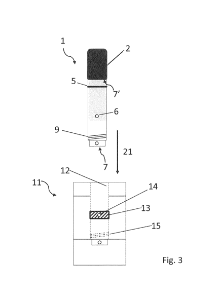
Fig. 3 shows coil member 1 that can be inserted into vaping
tank 11;
Fig. 4 shows a top view of a vaping device in which the coil
member can be switched between a use position 31 and a storage
position 32;
Fig. 5a shows a side view of the coil member inserted into the
vaping tank in a use position 31;
Fig. 5b shows a side view of the coil member inserted into the
vaping tank in a storage position 32; and
Fig. 6 shows in detail flange 8 provided on the coil member 1.
The terms electronic cigarette, e-cigarette, and vaping device
are often used interchangeably. Nonetheless, the term
electronic cigarette is sometimes used to indicate that the e-
liquid to be vaporized contains nicotine, whereas a vaping
device is understood to mean a device in which an e-liquid
without nicotine is used. The inventive heating coil and
vaping device work equally well in either case. Thus, the term
vaping device is used throughout this disclosure regardless of
the type of e-liquid used and encompasses vaping devices as
well as electronic cigarettes or e-cigarettes.
5
CA 03071792 2020-01-31
WO 2019/025543
PCT/EP2018/070994
Additionally, the term vaping tank is defined herein to
encompass the housing in which a tank portion for holding the
e-liquid is provided. However, the vaping tank may house other
components in addition to the tank portion, such as a battery
for powering the heating coil, a memory to store user
settings, or a display for displaying the fill level of the e-
liquid in the tank portion. Thus, the term vaping tank herein
means any housing that has at least a tank portion for holding
an e-liquid.
In the prior art as shown in Fig. 1, mouthpiece 2' and housing
3', which houses a vaping chamber and a heating coil, are
separate parts. Specifically, mouthpiece 2' is inserted into
housing 3' as indicated by arrow 20. When the deteriorated
heating coil needs to be replaced, the mouthpiece is detached
first before the housing 3' with the heating coil can be
replaced. Sometimes, the housing 3', which includes the
heating coil is referred to as "the coil" and replacing the
coil means that the entire housing 3' is replaced. Likewise,
mouthpiece 2' is replaceable separately from housing 3'.
For the purposes of clarity, the inventive housing unit that
includes the heating coil is herein referred to as the coil
member to indicate that a coil replacement involves replacing
of the entire coil member, and not merely the resistive wire
forming the heating coil.
When a heating coil in a prior art vaping device needs to be
replaced, the vaping chamber typically still contains e-liquid
and/or condensate. Because vaping chamber and mouthpiece are
in fluid communication, e-liquid may spill through the opening
on the housing 3' for receiving mouthpiece 2'. In some
instances, it also becomes difficult to remove the housing 3'
6
CA 03071792 2020-01-31
WO 2019/025543
PCT/EP2018/070994
from the vaping tank or the mouthpiece 2' may come off
unexpectedly during the replacement process.
To avoid the disadvantages of the prior art, and to provide an
easy, clean, and efficient way to replace a heating coil, the
instant coil member was invented. In the exemplary embodiment
of the invention shown in Fig. 2, an integrally formed coil
member 1 includes a vaping chamber 3 and a mouthpiece 2, which
are in fluid communication. The coil member 1 has an elongated
shape, typically cylindrical, and houses a heating coil 16 in
the vicinity of inflow opening 6. Commonly, a wicking material
(not shown) is provided with the heating coil 16. The wicking
material, sometimes also referred to as wadding, initially
absorbs the e-liquid before the e-liquid evaporates when the
heating coil 16 is powered up. Various arrangements of the
wicking material and the heating coil 16 are possible.
However, the various arrangements are not an objective of this
disclosure. Accordingly, this disclosure is not limited to the
arrangement shown in Fig. 2, but encompasses other
arrangements known to the skilled artisan.
The vaping chamber has an inlet end 7 and an outlet end 7'.
The resistive wire of the heating coil 16 heats up when an
electric current, typically provided by a battery, flows
through the heating coil 16 which vaporizes the e-liquid in
the wicking material. Air and vaporized e-liquid form a vapour
that flows in the general direction of a longitudinal axis of
the coil member from the inlet end 7 to the outlet end 7' of
the vaping chamber 3 into the mouthpiece 2. An opening 30 in
the mouthpiece allows the user to consume the vapour. In
proximity to the mouthpiece, i.e., toward the outlet end of
the vaping chamber, an exterior annular groove 4 is formed in
the external wall of the vaping chamber. Toward the inlet end
7, a first fastening unit 9 is arranged on the coil member 1.
7
CA 03071792 2020-01-31
WO 2019/025543
PCT/EP2018/070994
As noted above, Fig. 2 shows coil member 1 that includes a
vaping chamber 3, which has an exterior annular groove 4.
Typically, the annular groove is provided toward the outlet
end 7' of the vaping chamber 3. The exact location of annular
groove 4 is not critical, provided that the annular groove is
closer to the outlet end 7' than inlet opening 6.
Fig. 3 shows coil member 1 that is inserted into receiving
bore 12 of vaping tank 11 by pushing the coil member in the
direction of arrow 21. A floating internal collar 13 is
arranged within the receiving bore 12. The floating internal
collar 13 seals an outlet opening 14 arranged within the
receiving bore 12 when the coil member 1 is not inserted in
the vaping tank 11. The outlet opening 14 is in fluid
communication with the tank portion of vaping tank 11, where
the tank portion holds the e-liquid. When the coil member 1 is
inserted in the vaping tank 11, flange 8 catches the floating
internal collar 13 and pushes it down, such that the outlet
opening 14 becomes exposed. When the coil member is fully
inserted and the first fastening unit 9 and the second
fastening unit 15 are engaged, the coil member 1 can be held
in an operating position 31, in which the outlet opening 14
and the inlet opening 6 are aligned such that the e-liquid can
flow from the vaping tank 11 into the vaping chamber 3.
The first fastening unit 9 may be provided as an external
thread on the inlet end of the vaping chamber and the second
fastening unit as a matching internal thread within the
receiving bore 12. Screwing the coil member 1 into the
receiving bore 12 fastens the coil member 1 to the vaping tank
11 in the use position 31 shown in Fig. 4. In a particular
embodiment, partial unscrewing of the coil member results in a
misalignment of inlet opening 6 and outlet opening 14, such
that the vaping device may be stored without e-liquid loss. In
another particular embodiment, the second fastening unit 15 is
8
CA 03071792 2020-01-31
WO 2019/025543
PCT/EP2018/070994
rotatably mounted in the receiving bore 12. After the coil
member 1 is fully fastened, an additional application of
torque rotates the mount of the second fastening unit to
misalign inlet opening 6 and outlet opening 14 and to thereby
achieve the storage position 32 shown in Fig. 4. Thus, the
integrally formed coil member 1 also has the advantage of
making the vaping device 10 more user friendly because it is
simple and straightforward to switch between use and storage
position by simply twisting the mouth piece 2.
Fig. 3 further shows a seal 5 that is arranged in the external
annular groove 4. Typically, seal 5 is a silicone ring.
However, seal 5 may also be made from other materials, such as
vulcanized natural rubber. In addition, any other material
known to the skilled artisan having sealing properties may
also be used for the seal 5. Specifically, seal 5 prevents e-
liquid, vapour, or condensate from escaping the vaping device
from the gap between the receiving bore 12 and the coil member
1.
Fig. 4 shows a top view of vaping device 11 in which the coil
member 1 can be switched between a use position 31 and a
storage position 32. In particular, first fastening unit 9 and
second fastening unit 15 can be fully engaged such that the
coil member 1 is held in place when the vaping device 10 is
used. Moreover, a further turn of the mouthpiece 2 results in
the coil member 1 reaching storage position 32 in which the
vaping tank 11 and the vaping chamber 3 are no longer in fluid
communication, as illustrated in Fig. 5b. Instead, an exterior
wall of the coil member 1 seals outlet opening 14 and prevents
e-liquid from leaving the vaping tank 11. Accordingly, not
only coil replacement, but also ordinary use of the vaping
device can be performed more easily and in a more hygienic
manner.
9
CA 03071792 2020-01-31
WO 2019/025543
PCT/EP2018/070994
In an exemplary embodiment, a marking 33 is provided on the
mouthpiece 2 to indicate if the vaping device 10 is in use
position 31 or in storage position 32. Thus, the marking 33
serves as a visual indicator of the operating state of the
vaping device 10.
Fig. 5a shows a side view of the coil member 1 inserted into
the vaping tank 11. Specifically, Fig. 5a shows the vaping
device 10 in the use position 31 in which outlet opening 14
and inlet opening 6 are aligned such that vaping tank 11 and
vaping chamber 3 are in fluid communication. Seal 5 seals the
coil member 1 in the receiving bore 12 and prevents vapour or
e-liquid from escaping. Thus, vapour only leaves the vaping
device through the mouthpiece 2.
In Fig. 5b, which is also a side view of the coil member 1
inserted into the vaping tank 11, the vaping device is in
storage position 32 because inlet opening 6 and outlet opening
14 are not aligned to allow for fluid communication.
Fig. 6 shows in detail flange 8 provided on the coil member 1.
The flange 8 catches floating internal collar 13 when the coil
member 1 is inserted into the receiving bore 12 of vaping tank
11.
According to one aspect of the invention, a simpler, faster,
and cleaner way to replace a deteriorated heating coil 16 is
provided, making replacement more convenient and hassle free
for the consumer. In particular, a deteriorated heating coil
16 can be replaced more easily by removing the coil member 1
from the vaping tank 11 by simply twisting the mouth piece 2.
The foregoing description of the exemplary embodiments of the
disclosure illustrates and describes the present invention.
Additionally, the disclosure shows and describes only the
CA 03071792 2020-01-31
WO 2019/025543
PCT/EP2018/070994
exemplary embodiments but, as mentioned above, it is to be
understood that the disclosure is capable of use in various
other combinations, modifications, and environments and is
capable of changes or modifications within the scope of the
concept as expressed herein, commensurate with the above
teachings and/or the skill or knowledge of the related art.
The term "comprising" (and its grammatical variations) as used
herein is used in the inclusive sense of "having" or
"including" and not in the exclusive sense of "consisting only
of." The terms "a" and "the" as used herein are understood to
encompass the plural as well as the singular.
11
CA 03071792 2020-01-31
WO 2019/025543
PCT/EP2018/070994
Reference list
1 coil member
2 mouthpiece
2' mouthpiece
3 vaping chamber
3' housing
4 exterior annular groove
5 seal
6 inlet opening
7 inlet end
7' outlet end
8 flange
9 first fastening unit
10 vaping device
11 vaping tank
12 receiving bore
13 floating internal collar
14 outlet opening
15 second fastening unit
16 heating coil
20 arrow
21 arrow
opening
25 31 use position
32 storage position
33 marking
12