Note: Descriptions are shown in the official language in which they were submitted.
GROUND CONTOUR SENSING SYSTEM FOR CROP MOWING HEAD
Field of the Disclosure
[0001] The present disclosure relates to agricultural vehicles, and more
particularly to ground contour sensing systems for crop mowing heads attached
to
agricultural vehicles.
Background
[0002] Crop mowing heads for mowing hay and other crops can be damaged
or dulled and/or can damage the crop being mowed by hitting or cutting into
the
ground hidden by the crop before the crop is cut or mowed Crop density (lack
of
open spaces), roughness of terrain, and harshness of conditions in front of
the hay
mowing head make it difficult for ground contour sensing. Additional
challenges for a
ground contour sensing system on a crop mowing head can include avoidance of
cutting too close (hairpinning or scalping the crop), avoidance of hitting the
ground
and damaging the head, and/or generating crop buildup on the mechanism. The
current method is to employ a hydraulic float system that allows the mowing
head,
which can typically weigh around 6,000 pounds, to lightly float across the
ground.
However, float systems, whether mechanical or hydraulic, are limited in their
range of
operation, and their response times are delayed which can cause scalping of
the
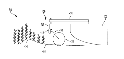
crop and head wear, especially wear on the cutterbar. Float systems for crop
mowing heads are currently only tied into the lift circuits of the head to
control vertical
downforce, but do not provide tilt control.
[0003] It would be desirable to have a ground contour sensing system for
a
crop mowing head that gives the head control system enough response time to
provide accurate ground contour following that avoids scalping the crop or
damaging
the mowing head. It would also be desirable for the ground contour sensing
system
to tie into the tilt circuit, in addition to lift or float circuits, of the
mowing head to
provide control of the attitude of the mowing head as well as the height.
1
CA 3072152 2020-02-11
Summary
[0004] A ground contour sensing system is disclosed for a vehicle with a
mowing head that moves across the ground. The ground contour sensing system
includes a first sensor system and a controller. The first sensor system
measures a
first ground contour of the ground in front of the mowing head, and generates
first
contour measurement signals. The controller receives the first contour
measurement
signals, determines whether to move the mowing head based on the first contour
measurement signals, and generates and sends movement commands to the
mowing head when it determines to move the mowing head based on the first
contour measurement signals.
[0005] The mowing head can include a tilt cylinder that tilts the front
of the
mowing head relative to the rear of the mowing head, and the controller can
determine whether to move the mowing head using the tilt cylinder based on the
first
contour measurement signals, and can generate and send movement commands to
the tilt cylinder when it determines to move the mowing head using the tilt
cylinder.
The mowing head can also include a lift cylinder that raises and lowers the
mowing
head relative to the ground; and the controller can determine whether to move
the
mowing head using the lift cylinder based on the first contour measurement
signals,
and can generate and send movement commands to the lift cylinder when it
determines to move the mowing head using the lift cylinder.
[0006] The first sensor system can include a pivot arm with a proximal
end and
a distal end, where the distal end moves in response to changes in the first
ground
contour in front of the mowing head, and where the first contour measurement
signals are based on movement of the pivot arm. The first sensor system can
also
include an angle sensor coupled to the proximal end of the pivot arm, where
the
angle sensor measures an angle of the pivot arm, and where the first contour
measurement signals are ground angle readings generated by the angle sensor.
The first sensor system can also include a coulter blade coupled to the distal
end of
the pivot arm, where the coulter blade travels along the ground in front of
the mowing
2
CA 3072152 2020-02-11
head. Alternatively, the distal end of the pivot arm can travel along the
ground in
front of the mowing head. The first sensor system can also include a stop
configured
to prevent movement of the proximal end of the first pivot arm beyond the
stop, and
where the proximal end of the pivot arm is biased towards the stop. The first
sensor
system can also include a connection arm with a proximal end and a distal end,
where the proximal end is coupled to the mowing head and the distal end is
coupled
to the angle sensor, and where the connection arm extends in front of the
mowing
head such that the angle sensor and the pivot arm are in front of the mowing
head.
[0007] The mowing head can extend laterally between a right side and a
left
side. The first sensor system can be positioned near the center between the
right
and left sides of the mowing head. The first sensor system can be positioned
near
the left side of the mowing head; and the ground contour sensing system can
also
include a second sensor system that measures a second ground contour of the
ground in front of the mowing head, and generates second contour measurement
signals; where the second sensor system is positioned near the right side of
the
mowing head. The controller can be configured to receive the first and second
contour measurement signals, to determine whether to move the mowing head
based
on the first and second contour measurement signals, and to generate and send
movement commands to the mowing head when it determines to move the mowing
head based on the first and second contour measurement signals.
[0008] The mowing head can include a tilt cylinder that tilts the front
of the
mowing head relative to the rear of the mowing head; a right lift cylinder
that raises
and lowers the right side of the mowing head relative to the left side of the
mowing
head; and a left lift cylinder that raises and lowers the left side of the
mowing head
relative to the right side of the mowing head. The controller can be
configured to
determine whether to move the mowing head using one or more of the tilt and
left
and right lift cylinders based on the first and second contour measurement
signals,
and to generate and send movement commands to the tilt and left and right lift
cylinders when it determines to move the mowing head using the tilt and left
and right
lift cylinders. The controller can be configured to determine whether to move
the
3
CA 3072152 2020-02-11
mowing head using the tilt cylinder based on the first and second contour
measurement signals, and to generate and send movement commands to the tilt
cylinder when it determines to move the mowing head using the tilt cylinder
based on
the first and second contour measurement signals. The controller can
configured to
determine whether to move the mowing head using the left lift cylinder based
on the
first contour measurement signals, and to generate and send movement commands
to the left lift cylinder when it determines to move the mowing head using the
left lift
cylinder; and to determine whether to move the mowing head using the right
lift
cylinder based on the second contour measurement signals, and to generate and
send movement commands to the right lift cylinder when it determines to move
the
mowing head using the right lift cylinder.
[0009] The first sensor system can include a first pivot arm with a
proximal end
and a distal end, where the distal end moves in response to changes in the
first
ground contour in front of the mowing head, and where the first contour
measurement signals are based on movement of the first pivot arm. The second
sensor system can include a second pivot arm with a proximal end and a distal
end,
where the distal end moves in response to changes in the second ground contour
in
front of the mowing head, and where the second contour measurement signals are
based on movement of the second pivot arm. The first sensor system can also
include a first angle sensor coupled to the proximal end of the first pivot
arm, where
the first angle sensor measures an angle of the first pivot arm, and the first
contour
measurement signals are ground angle readings generated by the first angle
sensor.
The second sensor system can also include a second angle sensor coupled to the
proximal end of the second pivot arm, where the second angle sensor measures
an
angle of the second pivot arm, and the second contour measurement signals are
ground angle readings generated by the second angle sensor.
[0010] A ground contour sensing method is disclosed for a vehicle with a
mowing head that moves across the ground. The ground contour sensing method
includes detecting a ground contour of the ground in front of the mowing head
using
a sensor system, generating contour measurement signals based on the detected
4
CA 3072152 2020-02-11
ground contour, determining whether to move the mowing head based on the
contour
measurement signals, and generating and sending movement commands to the
mowing head when it is determined to move the mowing head based on the contour
measurement signals. The mowing head can include a tilt cylinder that tilts
the front
of the mowing head relative to the rear of the mowing head, and a lift
cylinder that
raises and lowers the mowing head relative to the ground. Determining whether
to
move the mowing head based on the contour measurement signals can include
determining whether the contour measurement signals are in a tilt adjustment
region,
and determining whether the contour measurement signals are in a lift
adjustment
region. Generating and sending movement commands to the mowing head can
include generating and sending movement commands to the tilt cylinder when it
is
determined that the contour measurement signals are in the tilt adjustment
region,
and generating and sending movement commands to the lift cylinder when it is
determined that the contour measurement signals are in the lift adjustment
region.
[0011] The tilt cylinder can have an adjustment range. When it is
determined
that the contour measurement signals are in the lift adjustment region, the
method
can also include determining a desired tilt direction for the mowing head;
determining
whether the tilt cylinder can be further adjusted in the desired tilt
direction; and
generating and sending movement commands to the tilt cylinder to move in the
desired tilt direction when it is determined that the tilt cylinder can be
further adjusted
in the desired tilt direction.
[0012] The sensor system can include a pivot arm and an angle sensor,
where
the pivot arm has a proximal end coupled to the angle sensor and a distal end
that
moves in response to changes in the ground contour in front of the mowing
head.
Detecting a ground contour of the ground in front of the mowing head can
include
measuring an angle of the pivot arm using the angle sensor, and generating
contour
measurement signals can include generating ground angle signals based on the
measured angle of the pivot arm.
CA 3072152 2020-02-11
[0013] The ground contour sensing method can also include monitoring
speed
of the tractor; and generating movement commands based on the monitored speed
of the tractor.
Brief Description of the Drawings
[0014] The above-mentioned aspects of the present disclosure and the
manner of obtaining them will become more apparent and the disclosure itself
will be
better understood by reference to the following description of the embodiments
of the
disclosure, taken in conjunction with the accompanying drawings, wherein:
[0015] Figure 1 illustrates an exemplary embodiment of a tractor that
includes
a crop mowing head;
[0016] Figure 2 illustrates a closer view of the crop mowing head;
[0017] Figure 3 illustrates a portion of the crop mowing head with the
cover
removed;
[0018] Figure 4 illustrates an exemplary embodiment of a mowing head
with a
ground contour sensing system approaching a crop growing on the ground with a
bump under the crop;
[0019] Figure 5 illustrates an exemplary embodiment of a mowing head
with
an alternative ground contour sensing system approaching a crop growing on the
ground with a gully under the crop;
[0020] Figure 6 illustrates a block diagram of a ground contour sensing
system
communicating with a tractor controller that has tilt, float and lift
cylinders to move the
mowing head;
[0021] Figure 7 illustrates an exemplary adjustment diagram for a ground
contour sensing system; and
[0022] Figure 8 illustrates an exemplary control diagram for sending
commands to the tilt and lift/float cylinders based on readings from the
ground
contour sensing system.
[0023] Corresponding reference numerals are used to indicate
corresponding
= parts throughout the several views.
6
CA 3072152 2020-02-11
Detailed Description
[0024] The embodiments of the present disclosure described below are not
intended to be exhaustive or to limit the disclosure to the precise forms in
the
following detailed description. Rather, the embodiments are chosen and
described
so that others skilled in the art may appreciate and understand the principles
and
practices of the present disclosure.
[0025] Figure 1 illustrates an exemplary embodiment of a tractor 100
that
includes an engine compartment 110 that holds an engine, an operator cab 120,
front
wheels 130, rear wheels 140 and a crop mowing head 150. The exemplary tractor
100 shown in Figure 1 is a windrower. The front and rear wheels 130, 140
support
the tractor 100, including the engine compartment 110 and operator cab 120
above
the ground. In alternative tractor embodiments, tracks can be used instead of
wheels. The operator cab 120 includes controls for an operator to control the
tractor
100, including the engine, wheels 130, 140 and the crop mowing head 150. The
engine provides power to turn the wheels 130, 140 to propel the tractor 100.
At least
the front wheels 130 can be steerable to steer the tractor 100, and
alternatively both
the front and rear wheels 130, 140 can be steerable to steer the tractor 100.
The
operator cab 120 provides the operator with a clear view of the area being
worked by
the tractor 100 and crop mowing head 150.
[0026] The crop mowing head 150 is coupled to the front of the tractor
100.
Figure 2 illustrates a closer view of the crop mowing head 150. The crop
mowing
head 150 includes a tilt cylinder 210, a tilt axis 212, a float or lift
cylinder 220 and a
cover 230. The crop mowing head 150 has a front 214, a right side 216 and a
left
side 218. There are typically float and/or lift cylinders 220 on each side of
the crop
mowing head 150. The tilt cylinder 210 can tilt the crop mowing head 150 in
the fore-
aft direction about the tilt axis 212, which lifts or lowers the front 214 of
the mowing
head 150 relative to the tilt axis 212. The float or lift cylinder 220 can
raise and lower
the entire crop mowing head 150 vertically. With float or lift cylinders 220
at each of
the right and left ends 214, 216 of the mowing head, the right end float or
lift cylinder
7
CA 3072152 2020-02-11
220 can raise and lower the right end 214 relative to the left end 216 of the
mowing
head 150, and the left end float or lift cylinder 220 can raise and lower the
left end
216 relative to the right end 214 of the mowing head 150, and both the left
and right
float or lift cylinders 220 can raise and lower the entire mowing head 150
vertically.
The cover 230 covers the top of the crop mowing head 150.
[0027] Figure 3 illustrates a portion of the crop mowing head 150 with
the
cover 230 removed. The crop mowing head 150 includes a cutterbar 300,
conditioning rollers 330 and a skid plate 340. The cutterbar 300 includes a
plurality
of rotating heads 310, and each of the rotating heads 310 includes at least
one knife
or blade 312.
[0028] When in the operating position, the majority of the weight of the
mowing
head 150 is supported by the tractor 100 and the remaining weight produces a
downforce on the mowing head 150. During a cutting operation, the rotating
heads
310 of the cutterbar 300 rotate rapidly and the blades 312 cut the crop at a
cutting
height leaving stubble at that height. The cut material passes through the
conditioning rollers 330 which collect and condition the cut crop and lay it
behind the
mowing head 150. The crop mowing head 150 preferably floats just above the
ground with the skid plate 340 positioned below the cutterbar 300, so the
blades 312
cut the crop close to the ground and the skid plate 340 hits any mild
roughness to
help prevent the blades 312 from cutting into the ground. The operator can use
the
tilt cylinder 210 to angle the front 214 of the mowing head 150 up or down in
a sloped
area or rough terrain as needed to keep the blades 312 at a desired cutting
height or
height region above the ground, and to protect the mowing head 150 and blades
312
from hitting the ground and any debris. The operator can use the float and/or
lift
cylinders 220 to raise the mowing head 150 vertically in more severe terrain
as
desired to further protect the mowing head 150 and blades 312 from hitting the
ground and any debris. The problem is that before the crop is cut, it can be
challenging for an operator to know how severe the underlying terrain is that
the
mowing head is approaching.
8
CA 3072152 2020-02-11
[0029] Figure 4 illustrates an exemplary embodiment of a mowing head 400
with a ground contour sensing system 420 approaching a crop 452 growing on the
ground 450 with a bump 454 under the crop 452. The ground contour sensing
system 420 includes a connection arm 430, a ground angle sensor 434, a pivot
arm
436, a coulter blade 438 and a stop 440. The proximal end of the connection
arm
430 connects to the mowing head 400, and the distal end of the connection arm
430
connects to the ground angle sensor 434. The proximal end of the pivot arm 436
connects to the ground angle sensor 434, and the distal end of the pivot arm
436
connects to the coulter blade 438. The connection arm 430 extends in front of
the
mowing head 400 such that the ground angle sensor 434, pivot arm 436 and
coulter
blade 438 are in front of the mowing head 400, and the coulter blade 438 moves
along the ground 450 in front of the mowing head 400. The coulter blade 438
can be
thin (for example, 1/16 inch or less) to minimize crushing or pushing down of
the crop
before it is cut by the mowing head 400. The pivot arm 436 can be biased, for
example by a spring, to push towards the stop 440 so that when the coulter
blade
438 is lifted off the ground 450, the pivot arm 436 pushes against the stop
440. The
stop 440 prevents the pivot arm 436 from moving in front of the stop 440, such
that
the pivot arm 436 remains between the stop 440 and the mowing head 400 even
when the coulter blade 438 is not touching the ground 450.
[0030] As the coulter blade 438 moves along the ground 450, the ground
angle sensor 434 monitors the angle of the pivot arm 436, and the ground
contour
sensing system 420 sends ground angle readings back to a controller of the
tractor
100. The ground contour sensing system 420 can communicate with the controller
by wireless or wired communication methods. There can be multiple occurrences
of
the ground contour sensing system 420 on the mowing head 400; for example, one
sensing system 420 located near the center (between the left and right ends)
of the
mowing head 420, or sensing systems 420 located near each of the left and
right
ends of the mowing head 420, or sensing systems 420 located near each end and
the middle of the mowing head 420, or various other arrangements.
9
CA 3072152 2020-02-11
[0031] Figure 6 illustrates a block diagram of the ground contour
sensing
system 420 communicating with a controller 600 of a tractor that has one or
more tilt
cylinder(s) 610, float cylinder(s) 620 and lift cylinder(s) 630 to move the
mowing head
400. In some instances, one set of cylinders can serve as both float and lift
cylinders.
Using the ground angle readings, the controller 600 can anticipate the contour
of the
upcoming ground 450 even when hidden by the crop 452 and the controller 600
can
send commands to the tilt, float and lift cylinders 610, 620, 630 to move the
mowing
head 400 accordingly to help prevent damage or dulling of the blades 312 in
the
mowing head 400 by hitting the ground 450, and to try to keep the blades 312
of the
mowing head 400 within a desired height region above the ground 450.
[0032] Figure 7 illustrates an exemplary adjustment diagram for a ground
contour sensing system 420. This example will be described with reference to
figures 4 and 6, and assuming increasing ground angle readings indicate an
upward
change in ground contour and decreasing ground angle readings indicate a
downward change in ground contour. The opposite could be the case as would be
understood by those of ordinary skill in the art.
[0033] If the ground angle readings stay within a normal region 702,
indicating
fairly smooth, flat ground then no adjustment of the tilt, float or lift
cylinders 610, 620,
630 is required. When the ground angle readings go above an upper tilt
threshold,
the ground contour sensing system 420 enters an upper tilt adjustment region
710
where the tilt cylinders 610 are activated to increase the angle of the mowing
head
400 to try to avoid the blades of the mowing head 400 from hitting the ground.
The
tilt cylinders 610 typically have a tilt adjustment range, for example +/- 10
degrees. If
the ground angle readings continue to increase and go above an upper lift
threshold,
the ground contour sensing system 420 enters an upper lift/float adjustment
region
720 where the lift and/or float cylinders 620, 630 are also activated to lift
the mowing
head 400 to try to avoid the blades of the mowing head 400 from hitting the
ground.
The tilt cylinders 610 can continue to be adjusted in the upper lift/float
adjustment
region 720 if the tilt cylinders have not yet reached the upper limit of their
tilt
adjustment range. When the ground angle readings start decreasing back down,
the
CA 3072152 2020-02-11
ground contour sensing system 420 lowers the mowing head 400 with the lift
and/or
float cylinders 620, 630. When the ground angle readings decrease back down
below the upper lift threshold into the upper tilt adjustment region 710, the
ground
contour sensing system 420 also starts decreasing the tilt angle of the mowing
head
400 with the tilt cylinders 610. When the ground angle readings decrease back
down
below the upper tilt threshold into the normal region 702, the ground contour
sensing
system 420 can continue to adjust the tilt, float and lift cylinders 610, 620,
630 back
to their default settings for level mowing.
[0034] The ground contour sensing system 420 can act similarly to lower
the
mowing head 400 when the ground angle readings decrease below the normal
region 702. When the ground angle readings go below a lower tilt threshold,
the
ground contour sensing system 420 enters a lower tilt adjustment region 712
where
the tilt cylinders 610 are activated to decrease the angle of the mowing head
400 to
try to keep the blades of the mowing head 400 within a desired height region
above
the ground. If the ground angle readings continue to decrease and go below a
lower
lift threshold, the ground contour sensing system 420 enters a lower
lift/float
adjustment region 722 where the lift and/or float cylinders 620, 630 are also
activated
to lower the mowing head 400 to try to keep the blades of the mowing head 400
within a desired height region above the ground. The tilt cylinders 610 can
continue
to be adjusted in the lower lift/float adjustment region 722 if the tilt
cylinders have not
yet reached the lower limit of their tilt adjustment range. When the ground
angle
readings start increasing back up, the ground contour sensing system 420
raises the
mowing head 400 with the lift and/or float cylinders 620, 630. When the ground
angle readings increase back above the lower lift threshold into the lower
tilt
adjustment region 712, the ground contour sensing system 420 also starts
increasing
the tilt angle of the mowing head 400 with the tilt cylinders 610. When the
ground
angle readings increase back above the lower tilt threshold into the normal
region
702, the ground contour sensing system 420 can continue to adjust the tilt,
float and
lift cylinders 610, 620, 630 back to their default settings for level mowing.
11
CA 3072152 2020-02-11
[0035] The upper and lower thresholds can but do not have to have the
same
absolute value. As an example, but not for limitation, the upper and lower
tilt
thresholds can be +/- 1 degree, respectively, and the upper and lower lift
thresholds
can be +/- 10 degrees, respectively. The ground contour sensing system 420 can
also take the speed of the vehicle and/or the reaction time of the hydraulic
system
and cylinders into account and adjust the tilt, float or lift cylinders 610,
620, 630 more
rapidly and/or decrease the absolute values of the tilt and lift thresholds
based on the
vehicle speed.
[0036] In Figure 4, as the coulter 438 moves along the ground 450 before
reaching the bump 454, the angle sensor 434 monitors the angle of the pivot
arm 436
and the ground angle readings remain fairly steady in a normal range
indicating a
relatively flat, smooth ground contour. When the coulter blade 438 reaches the
bump
454, the pivot arm 436 would move back towards the mowing head 400 and the
ground angle readings would change (increase or decrease) to indicate an
upcoming
bump or hill. Depending on the size and steepness of the upcoming bump or
hill, the
speed of the tractor and other factors the tilt, lift and float cylinders 610,
620, 630 can
be activated to help prevent damage or dulling of the mowing head 400 and its
blades, and to try to keep the blades 312 of the mowing head 400 within a
desired
height region above the ground 450.
[0037] The upper and lower tilt thresholds can be established at the
upper and
lower edges of a normal range 702, such that when the angle of the pivot arm
436
reaches one of the tilt thresholds, the tilt cylinder 610 is activated to
start tilting the
mowing head 400 in the appropriate direction to try to keep the blades 312 of
the
mowing head 400 within a desired height region above the ground 450. When the
angle of the pivot arm 436 is greater than the upper tilt threshold and enters
the
upper tilt adjustment region 710, the tilt cylinder 610 can be activated to
tilt up the
front of the mowing head 400 by an amount that is a function of the difference
between the angle of the pivot arm 436 and the upper tilt threshold. When the
angle
of the pivot arm 436 is less than the lower tilt threshold and enters the
lower tilt
adjustment region 712, the tilt cylinder 610 can be activated to tilt down the
front of
12
CA 3072152 2020-02-11
the mowing head 400 by an amount that is a function of the difference between
the
angle of the pivot arm 436 and the lower tilt threshold.
[0038] The upper and lower lift thresholds are established where the
float/lift
cylinders 620, 630 are also activated. The upper lift threshold is typically
greater than
the upper tilt threshold, the lower lift threshold is typically less than the
lower tilt
threshold, so the controller 600 would initially react to a ground contour
change using
the tilt cylinder 610 and if the contour change was more significant
supplement
movement using the float/lift cylinders 620, 630. When the angle of the pivot
arm 436
reaches one of the lift thresholds, the float/lift cylinders 620, 630 are
activated to start
lifting/lowering the mowing head 400 in the appropriate direction to try to
keep the
blades 312 of the mowing head 400 within the desired height region above the
ground 450. When the angle of the pivot arm 436 is greater than the upper lift
threshold and enters the upper lift/float adjustment region 720, the
float/lift cylinders
620, 630 can be activated to lift up the mowing head 400 by an amount that is
a
function of the difference between the angle of the pivot arm 436 and the
upper lift
threshold. When the angle of the pivot arm 436 is less than the lower lift
threshold
and enters the lower lift/float adjustment region 722, the float/lift
cylinders 620, 630
can be activated to lower the mowing head 400 by an amount that is a function
of the
difference between the angle of the pivot arm 436 and the lower lift
threshold. If the
mowing head 400 has ground contour sensing systems 420 and float/lift
cylinders
620, 630 on each side of the mowing head 400, then the float/lift cylinders
620, 630
on each side can be controlled independently based on the angle readings from
the
ground contour sensing systems 420 on its side of the mowing head 400.
[0039] Figure 5 illustrates an exemplary embodiment of a mowing head 500
with an alternative embodiment of a ground contour sensing system 520
approaching
a crop 552 growing on the ground 550 with a gully 554 under the crop 552. The
ground contour sensing system 520 includes a connector 530, an angle sensor
534,
a pivot arm 536 and a stop 540. The connector 530 connects the angle sensor
534
and the proximal end of the pivot arm 536 to the mowing head 500. The distal
end of
the pivot arm 536 touches and moves along the ground 550 in front of the
mowing
13
CA 3072152 2020-02-11
head 500. The pivot arm 536 can be thin (for example, 1/32 inch or less) to
minimize
crushing or pushing down of the crop before it is cut by the mowing head 500.
The
pivot arm 536 can be biased, for example by a spring, to push towards the stop
540
so that when the pivot arm 536 is not touching the ground 550, the pivot arm
536
pushes against the stop 540. The stop 540 prevents the pivot arm 536 from
moving
in front of the stop 540, such that the pivot arm 536 remains between the stop
540
and the mowing head 500 even when the pivot arm 536 is not touching the ground
550.
[0040] As the pivot arm 536 moves along the ground 550, the angle sensor
534 monitors the angle of the pivot arm 536, and the ground contour sensing
system
520 sends ground angle readings back to a controller of the tractor 100. The
ground
contour sensing system 520 can communicate with the controller by wireless or
wired
communication methods. There can be multiple occurrences of the ground contour
sensing system 520 on the mowing head 500; for example, one sensing system 520
near the center of the mowing head 500, or sensing systems 520 located near
each
of the left and right ends of the mowing head 500, or sensing systems 520
located
near each end and the middle of the mowing head 500, or various other
arrangements. The normal angle range, upper and lower tilt thresholds, upper
and
lower lift thresholds and activation of the tilt, float and lift cylinders
610, 620, 630 as
described with regard to the ground contour sensing system 420 can also apply
to
the alternative embodiment of the ground contour sensing system 520.
[0041] Figure 8 illustrates an exemplary control diagram 800 for sending
commands to the tilt and lift/float cylinders 610, 620, 630 based on ground
angle
readings from the ground contour sensing system 420. A similar control flow
can be
used with the sensing system 520 and other ground contour sensing systems.
Based upon characteristics of the mowing head 400, positioning of the ground
contour sensing system 420 relative to the mowing head 400, and other factors,
a
user can determine the desired tilt and lift thresholds for the system that
can be used
as described below.
14
CA 3072152 2020-02-11
[0042] At block 802, the controller 600 monitors the ground angle
readings
from the contour sensing system 420. When the coulter blade 438 is moving
along
fairly smooth and level ground, the angle of the pivot arm 436 stays
relatively steady
and the angle readings remain in the normal range 702 between the upper and
lower
tilt thresholds. Angle readings in the normal range indicate relatively smooth
and
level ground that does not require tilting or lifting of the mower head 400.
Thus, the
mowing head 400 can stay at a normal position floating a desired distance
above the
ground 450. At block 804, the controller 600 checks whether the current ground
angle reading is in the normal range 702. If the current ground angle reading
is in
the normal range 702, then control returns to block 802 and the mowing head
400 is
not moved, otherwise control passes to block 810.
[0043] At block 810, the controller 600 checks whether the current
ground
angle reading is in the upper tilt adjustment region 710 between the upper
tilt and lift
thresholds, or in the lower tilt adjustment region 712 between the lower tilt
and lift
thresholds. If the current angle reading is in one of the upper or lower tilt
adjustment
regions 710, 712, then control passes to block 812. When the current ground
angle
reading is greater than the upper lift threshold it is in the upper lift/float
adjustment
region 720, and when the current angle reading is less than the lower lift
threshold it
is in a lower lift/float adjustment region 722. If the current ground angle
reading is in
one of the upper or lower lift/float adjustment regions 720, 722, then control
passes
to block 822.
[0044] At block 812, the controller 600 sends commands to the tilt
cylinder 610
to adjust for the upcoming change in ground contour. Block 812 also receives a
speed input from block 830 which indicates the speed at which the mowing head
400
is moving forward. When the coulter blade 438 starts rolling up or down a hill
or hits
debris the angle of the pivot arm 436 changes. For example, when the coulter
blade
438 starts rolling up the bump 454 as shown in Figure 4, the pivot arm 436 is
pushed
back towards the mowing head 400 which changes the readings of the angle
sensor
434 which indicates that the mowing head 400 is approaching an uphill ground
contour. As another example, when the pivot arm 536 starts going down the
gully
CA 3072152 2020-02-11
554 as shown in Figure 5, the pivot arm 536 moves forward away from the mowing
head 500 which changes the readings of the angle sensor 534 and indicates that
the
mowing head 500 is approaching a downhill ground contour. When the readings of
the angle sensor 434 are in one of the upper or lower tilt adjustment regions
710,
712, the controller 600 can send commands to the tilt cylinder 610 to tilt the
mowing
head 400 in the appropriate direction and/or by the appropriate magnitude
indicated
by the ground angle readings. For example, in the situation illustrated in
Figure 4,
the controller 600 can command the tilt cylinder 610 to tilt up the front of
the mowing
head 400 based on the speed of the mowing head 400 and the difference between
the current ground angle readings of the angle sensor 434 and the upper tilt
threshold. For example, in the situation illustrated in Figure 5, the
controller 600 can
command the tilt cylinder 610 to tilt down the front of the mowing head 500
based on
the speed of the mowing head 500 and the difference between the current ground
angle readings of the angle sensor 534 and the lower tilt threshold. Faster
speeds
may require a greater change in tilt angle, or may lower the magnitude of the
angle of
the upper and lower tilt and lift thresholds.
[0045] Control passes from block 812 to block 814. At block 814, the
controller 600 checks whether lift/float cylinders 620, 630 are active or not
in their
normal or default positions for level mowing. When the ground angle readings
are
within the tilt adjustment region (between the upper and lower lift
thresholds) as they
are at this point, it may be desirable to move the lift/float cylinders 620,
630 back to
their normal positions and just use the tilt cylinder 610 for ground contour
adjustment.
If the lift/float cylinders 620, 630 are not active, then control returns to
block 802 to
get further ground angle readings. If the lift/float cylinders 620, 630 are
active, then
control passes to block 816 where the lift/float cylinders 620, 630 are
adjusted back
towards their normal positions, and then control returns to block 802 to get
further
ground angle readings.
[0046] At block 822, the controller 600 sends commands to the lift/float
cylinders 620, 630 to adjust for the upcoming change in ground contour. Block
822
also receives a speed input from block 830 which indicates the speed at which
the
16
CA 3072152 2020-02-11
mowing head 400 is moving forward. A PID (proportional-integral-derivative)
control
loop can be used to process the ground angle and speed inputs to calculate the
magnitude and rate of change for the commands to the lift/float cylinders 620,
630.
When the coulter blade 438 starts rolling up or down a steeper hill or hits
more
severe debris the angle of the pivot arm 436 changes more rapidly and by a
greater
amount. For example, if the bump 454 shown in Figure 4 is steeper, the coulter
blade 438 moves the pivot arm 436 more rapidly towards the mowing head 400
which changes the readings of the angle sensor 434 faster which indicates that
the
mowing head 400 is approaching a steep uphill ground contour. As another
example, if the gully 554 shown in Figure 5 has steeper banks, when the pivot
arm
536 starts going down the gully 554, the pivot arm 536 moves forward faster
and may
swing against the stop 540 which changes the readings of the angle sensor 534
faster and indicates that the mowing head 500 is approaching a steep downhill
ground contour. When the readings of the angle sensor 434 are in one of the
upper
or lower lift/float adjustment regions 720, 722, the controller 600 can send
commands
to the lift/float cylinders 620, 630 to lift the mowing head 400 in the
appropriate
direction and/or by the appropriate magnitude indicated by the angle readings.
For
example, in the situation illustrated in Figure 4, the controller 600 can
command the
lift/float cylinders 620, 630 to raise the mowing head 400 based on the speed
of the
mowing head 400 and the difference between the current ground angle readings
of
the angle sensor 434 and the upper lift threshold. If the mowing head 400 has
ground contour sensing systems 420 and lift/float cylinders 620, 630 on both
the left
and right sides, then the controller 600 can command the left and right
lift/float
cylinders 620, 630 independently based on the angle readings from the ground
contour sensing system 420 on the same side. Faster speeds may require a
greater
lift of the mowing head 400, or may lower the magnitude of the angle of the
upper
and lower lift thresholds.
[0047] Control passes from block 822 to block 824. At block 824, the
controller 600 checks whether the tilt cylinder(s) 610 still have adjustment
range
available. The tilt cylinder 610 can continue to tilt the mowing head 400 in
the
17
CA 3072152 2020-02-11
appropriate direction even when the ground angle readings are in the upper or
lower
lift/float adjustment regions 720, 722. If the tilt cylinder(s) 610 do not
have
adjustment range available, then control returns to block 802 to get further
ground
angle readings. If the tilt cylinder(s) 610 still have adjustment range
available, then
control passes to block 816 where the tilt cylinder(s) 610 are adjusted in the
appropriate direction, and then control returns to block 802 to get further
ground
angle readings.
[0048]
While the disclosure has been illustrated and described in detail in the
drawings and foregoing description, such illustration and description is to be
considered as exemplary and not restrictive in character, it being understood
that
illustrative embodiment(s) have been shown and described and that all changes
and
modifications that come within the spirit of the disclosure are desired to be
protected.
It will be noted that alternative embodiments of the present disclosure may
not
include all of the features described yet still benefit from at least some of
the
advantages of such features. Those of ordinary skill in the art may readily
devise
their own implementations that incorporate one or more of the features of the
present
disclosure and fall within the spirit and scope of the present invention as
defined by
the appended claims.
18
CA 3072152 2020-02-11