Note: Descriptions are shown in the official language in which they were submitted.
CA 03072657 2020-02-11
WO 2019/033197
PCT/CA2018/050901
VARIED LENGTH METAL STUDS
Technical Field
The present disclosure relates to structural members, and
more particularly, to metal studs.
BACKGROUND
Description of the Related Art
Metal studs and framing members have been used in the
areas of commercial and residential construction for many years. Metal
studs offer a number of advantages over traditional building materials, such
as wood. For instance, metal studs can be manufactured to have strict
dimensional tolerances, which increase consistency and accuracy during
construction of a structure. Moreover, metal studs provide dramatically
improved design flexibility due to the variety of available sizes and
thicknesses and variations of metal materials that can be used. Moreover,
metal studs have inherent strength-to-weight ratios which allow them to
span longer distances and better resist and transmit forces and bending
moments.
BRIEF SUMMARY
The various embodiments described herein may provide a
stud with enhanced thermal efficiency over more conventional studs. While
metals are typically classed as good thermal conductors, the studs
described herein employ various structures and techniques to reduce
conductive thermal transfer thereacross. For instance, use of a wire matrix,
welds such as resistance welds, and specific weld locations such as at
peaks, apexes, or intersections of the wires in the wire matrix, may
contribute to the overall energy efficiency of the stud.
1
CA 03072657 2020-02-11
WO 2019/033197
PCT/CA2018/050901
It has been found that light-weight metal studs incorporating a
wire matrix can be strengthened, or in some cases their rigidity or stability
and can be increased, such as to increase web crippling strengths of the
ends of the studs, by fabricating the studs so that ends of the wires in the
wire matrix are located at and/or welded to ends of channel members of the
studs.
It has also been found that the ability to manufacture studs to
any specific length provides distinct advantages, such as improving the
efficiency of installation of the studs at a work site. Thus, systems and
methods have been developed that allow the continuous fabrication of
metal studs having various lengths and having ends of wires in a wire
matrix located at and/or welded to ends of channel members of the studs.
Such methods generally include continuously fabricating a wire matrix and
stretching the wire matrix to various degrees corresponding to the various
lengths of the studs to be fabricated, before welding the wire matrix to
channel members.
A light-weight metal stud may be summarized as comprising:
a first elongated channel member, the first elongated channel member
having a respective major face having a respective first edge along a major
length thereof and a respective second edge along the major length
thereof, a respective first flange extending along the first edge at a non-
zero
angle to the respective major face of the first elongated channel member, a
respective second flange extending along the second edge at a non-zero
angle to the respective major face of the first elongated channel member, a
respective first end along the major length thereof, and a respective second
end along the major length thereof, the first end of the first elongated
channel member opposite to the second end of the first elongated channel
member across the major length of the first elongated channel member; a
second elongated channel member, the second elongated channel member
having a respective major face having a respective first edge along a major
length thereof and a respective second edge along the major length
2
CA 03072657 2020-02-11
WO 2019/033197
PCT/CA2018/050901
thereof, a respective first flange extending along the first edge at a non-
zero
angle to the respective major face of the second elongated channel
member, a respective second flange extending along the second edge at a
non-zero angle to the respective major face of the second elongated
channel member, a respective first end along the major length thereof, and
a respective second end along the major length thereof, the first end of the
second elongated channel member opposite to the second end of the
second elongated channel member across the major length of the second
elongated channel member; a first continuous wire member having a
plurality of bends to form alternating apexes along a respective length
thereof, a respective first end along the respective length thereof, and a
respective second end along the respective length thereof, the first end of
the first continuous wire member opposite to the second end of the first
continuous wire member across the length of the first continuous wire
member, the apexes of the first continuous wire member alternatively
physically attached to the first and the second elongated channel members
along at least a portion of the first and the second elongated channel
members, the first end of the first continuous wire member coupled to the
first elongated channel member at the first end of the first elongated
channel member, and the second end of the first continuous wire member
coupled to either the first or the second elongated channel member at the
second end of either the first or the second elongated channel member;
and a second continuous wire member having a plurality of bends to form
alternating apexes along a respective length thereof, a respective first end
along the respective length thereof, and a respective second end along the
respective length thereof, the first end of the second continuous wire
member opposite to the second end of the second continuous wire member
across the length of the second continuous wire member, the apexes of the
second continuous wire member alternatively physically attached to the first
and the second elongated channel members along at least a portion of the
first and the second elongated channel members, the first end of the
3
CA 03072657 2020-02-11
WO 2019/033197
PCT/CA2018/050901
second continuous wire member coupled to the second elongated channel
member at the first end of the second elongated channel member, the
second end of the second continuous wire member coupled to the second
end of either the first or the second elongated channel member, and the
first and the second elongated channel members held in spaced apart
parallel relation to one another by both of the first and the second wire
members, with a longitudinal passage formed therebetween.
The first and the second wire members may be physically
attached to one another at each point at which the first and the second wire
members cross one another. Each of the apexes of the second wire
member may be opposed to a respective one of the apexes of the first wire
member across the longitudinal passage. The first and the second
continuous wires may be physically attached to the respective first flange of
both the first and the second elongated channel member by welds and do
not physically contact the respective major faces of the first and the second
elongated channel members. The welds may be resistance welds. The
apexes of the first continuous wire member attached to the first elongated
channel member may alternate with the apexes of the second continuous
wire member attached to the first elongated channel member such that a
difference between a largest distance between adjacent ones of the apexes
of the first and second continuous wires attached to the first elongated
channel member and a smallest distance between adjacent ones of the
apexes of the first and second continuous wires attached to the first
elongated channel member is at least 1% of a mean distance between
adjacent ones of the apexes of the first and second continuous wires
attached to the first elongated channel member. The first and second
continuous wire members may be plastically deformed wire members. The
first and second continuous wire members may carry residual stresses.
A light-weight metal stud may be summarized as comprising:
a first elongated channel member, the first elongated channel member
having a respective major face having a respective first edge along a major
4
CA 03072657 2020-02-11
WO 2019/033197
PCT/CA2018/050901
length thereof and a respective second edge along the major length
thereof, a respective first flange extending along the first edge at a non-
zero
angle to the respective major face of the first elongated channel member,
and a respective second flange extending along the second edge at a non-
zero angle to the respective major face of the first elongated channel
member; a second elongated channel member, the second elongated
channel member having a respective major face having a respective first
edge along a major length thereof and a respective second edge along the
major length thereof, a respective first flange extending along the first edge
at a non-zero angle to the respective major face of the second elongated
channel member, and a respective second flange extending along the
second edge at a non-zero angle to the respective major face of the second
elongated channel member; a first continuous wire member having a
plurality of bends to form alternating apexes along a respective length
thereof, the apexes of the first continuous wire member alternatively
physically attached to the first and the second elongated channel members
along at least a portion of the first and the second elongated channel
members; and a second continuous wire member having a plurality of
bends to form alternating apexes along a respective length thereof, the
apexes of the second continuous wire member alternatively physically
attached to the first and the second elongated channel members along at
least a portion of the first and the second elongated channel members, the
apexes of the first continuous wire member attached to the first elongated
channel member alternating with the apexes of the second continuous wire
member attached to the first elongated channel member such that a
difference between a largest distance between adjacent ones of the apexes
of the first and second continuous wires attached to the first elongated
channel member and a smallest distance between adjacent ones of the
apexes of the first and second continuous wires attached to the first
elongated channel member is at least 1% of a mean distance between
adjacent ones of the apexes of the first and second continuous wires
5
CA 03072657 2020-02-11
WO 2019/033197
PCT/CA2018/050901
attached to the first elongated channel member, the first and the second
elongated channel members held in spaced apart parallel relation to one
another by both of the first and the second wire members, with a
longitudinal passage formed therebetween.
A difference between a largest distance between adjacent
ones of the apexes of the first and second continuous wires attached to the
first elongated channel member and a smallest distance between adjacent
ones of the apexes of the first and second continuous wires attached to the
first elongated channel member may be at least 2%, 3%, or 5% of a mean
distance between adjacent ones of the apexes of the first and second
continuous wires attached to the first elongated channel member.
A method of making a light-weight metal stud may be
summarized as comprising: providing a first elongated channel member
having a respective major face having a respective first edge along a major
length thereof and a respective second edge along the major length
thereof, a respective first flange extending along the first edge at a non-
zero
angle to the respective major face of the first elongated channel member,
and a respective second flange extending along the second edge at a non-
zero angle to the respective major face of the first elongated channel
member; providing a second elongated channel member having a
respective major face having a respective first edge along a major length
thereof and a respective second edge along the major length thereof, a
respective first flange extending along the first edge at a non-zero angle to
the respective major face of the second elongated channel member, and a
respective second flange extending along the second edge at a non-zero
angle to the respective major face of the second elongated channel
member; tensioning a wire matrix including first and second continuous wire
members, each of the first and second wire members having a plurality of
bends to form alternating apexes along a respective length thereof; and
coupling the first and the second elongated channel members together with
the tensioned wire matrix, the apexes of the first continuous wire member
6
CA 03072657 2020-02-11
WO 2019/033197
PCT/CA2018/050901
alternatively physically attached to the first and the second elongated
channel members along at least a portion of the first and the second
elongated channel members, and the apexes of the second continuous wire
member alternatively physically attached to the first and the second
elongated channel members along at least a portion of the first and the
second elongated channel members.
The method may further comprise physically attaching the first
and the second continuous wire members to one another at intersection
points thereof. The physically attaching the first and the second continuous
wire members to one another at intersection points thereof may occur
before the coupling the first and the second elongated channel members
together by the wire matrix. Tensioning the wire matrix may include
tensioning the wire matrix along a longitudinal axis of the wire matrix.
Tensioning the wire matrix may include plastically and/or elastically
deforming the wire matrix.
A plurality of studs may be summarized as comprising: a first
light weight stud having a first length, the first stud including: a first
elongated channel member, the first elongated channel member having a
respective major face having a respective first edge along a major length
thereof and a respective second edge along the major length thereof, a
respective first flange extending along the first edge at a non-zero angle to
the respective major face of the first elongated channel member, a
respective second flange extending along the second edge at a non-zero
angle to the respective major face of the first elongated channel member, a
respective first end along the major length thereof, and a respective second
end along the major length thereof, the first end of the first elongated
channel member opposite to the second end of the first elongated channel
member across the major length of the first elongated channel member; a
second elongated channel member, the second elongated channel member
having a respective major face having a respective first edge along a major
length thereof and a respective second edge along the major length
7
CA 03072657 2020-02-11
WO 2019/033197
PCT/CA2018/050901
thereof, a respective first flange extending along the first edge at a non-
zero
angle to the respective major face of the second elongated channel
member, a respective second flange extending along the second edge at a
non-zero angle to the respective major face of the second elongated
channel member, a respective first end along the major length thereof, and
a respective second end along the major length thereof, the first end of the
second elongated channel member opposite to the second end of the
second elongated channel member across the major length of the second
elongated channel member; a first continuous wire member having a
plurality of bends to form alternating apexes along a respective length
thereof, a respective first end along the respective length thereof, and a
respective second end along the respective length thereof, the first end of
the first continuous wire member opposite to the second end of the first
continuous wire member across the length of the first continuous wire
member, the apexes of the first continuous wire member alternatively
physically attached to the first and the second elongated channel members
along at least a portion of the first and the second elongated channel
members, the first end of the first continuous wire member coupled to the
first end of the first elongated channel member, and the second end of the
first continuous wire member coupled to the second end of either the first or
the second elongated channel member; and a second continuous wire
member having a plurality of bends to form alternating apexes along a
respective length thereof, a respective first end along the respective length
thereof, and a respective second end along the respective length thereof,
the first end of the second continuous wire member opposite to the second
end of the second continuous wire member across the length of the second
continuous wire member, the apexes of the second continuous wire
member alternatively physically attached to the first and the second
elongated channel members along at least a portion of the first and the
second elongated channel members, the first end of the second continuous
wire member coupled to the first end of the second elongated channel
8
CA 03072657 2020-02-11
WO 2019/033197
PCT/CA2018/050901
member, the second end of the second continuous wire member coupled to
the second end of either the first or the second elongated channel member,
the apexes of the first continuous wire member attached to the first
elongated channel member spaced apart from adjacent apexes of the
second continuous wire member attached to the first elongated channel
member by a first pitch, and the first and the second elongated channel
members held in spaced apart parallel relation to one another by both of
the first and the second wire members, with a longitudinal passage formed
therebetween; and a second light weight stud having a second length, the
second stud including: a third elongated channel member, the third
elongated channel member having a respective major face having a
respective first edge along a major length thereof and a respective second
edge along the major length thereof, a respective first flange extending
along the first edge at a non-zero angle to the respective major face of the
third elongated channel member, a respective second flange extending
along the second edge at a non-zero angle to the respective major face of
the third elongated channel member, a respective first end along the major
length thereof, and a respective second end along the major length thereof,
the first end of the third elongated channel member opposite to the second
end of the third elongated channel member across the major length of the
third elongated channel member; a fourth elongated channel member, the
fourth elongated channel member having a respective major face having a
respective first edge along a major length thereof and a respective second
edge along the major length thereof, a respective first flange extending
along the first edge at a non-zero angle to the respective major face of the
fourth elongated channel member, a respective second flange extending
along the second edge at a non-zero angle to the respective major face of
the fourth elongated channel member, a respective first end along the
major length thereof, and a respective second end along the major length
thereof, the first end of the fourth elongated channel member opposite to
the second end of the fourth elongated channel member across the major
9
CA 03072657 2020-02-11
WO 2019/033197
PCT/CA2018/050901
length of the fourth elongated channel member; a third continuous wire
member having a plurality of bends to form alternating apexes along a
respective length thereof, a respective first end along the respective length
thereof, and a respective second end along the respective length thereof,
the first end of the third continuous wire member opposite to the second
end of the third continuous wire member across the length of the third
continuous wire member, the apexes of the third continuous wire member
alternatively physically attached to the third and the fourth elongated
channel members along at least a portion of the third and the fourth
elongated channel members, the first end of the third continuous wire
member coupled to the first end of the third elongated channel member,
and the second end of the third continuous wire member coupled to the
second end of either the third or the fourth elongated channel member; and
a fourth continuous wire member having a plurality of bends to form
alternating apexes along a respective length thereof, a respective first end
along the respective length thereof, and a respective second end along the
respective length thereof, the first end of the fourth continuous wire member
opposite to the second end of the fourth continuous wire member across
the length of the fourth continuous wire member, the apexes of the fourth
continuous wire member alternatively physically attached to the third and
the fourth elongated channel members along at least a portion of the third
and the fourth elongated channel members, the first end of the fourth
continuous wire member coupled to the first end of the fourth elongated
channel member, the second end of the fourth continuous wire member
coupled to the second end of either the third or the fourth elongated
channel member, the apexes of the third continuous wire member attached
to the third elongated channel member spaced apart from adjacent apexes
of the fourth continuous wire member attached to the third elongated
channel member by a second pitch, and the third and the fourth elongated
channel members held in spaced apart parallel relation to one another by
both of the third and the fourth wire members, with a longitudinal passage
CA 03072657 2020-02-11
WO 2019/033197
PCT/CA2018/050901
formed therebetween; wherein the first length differs from the second length
and the first pitch differs from the second pitch.
The first length may differ from the second length by an
amount that is not a multiple of either the first pitch or the second pitch.
The first length may differ from the second length by 1 inch. The first length
may differ from the second length by less than 1/2 inch.
BRIEF DESCRIPTION OF THE SEVERAL VIEWS OF THE DRAWINGS
In the drawings, identical reference numbers identify similar
elements or acts. The sizes and relative positions of elements in the
drawings are not necessarily drawn to scale. For example, the shapes of
various elements and angles are not necessarily drawn to scale, and some
of these elements may be arbitrarily enlarged and positioned to improve
drawing legibility. Further, the particular shapes of the elements as drawn
are not necessarily intended to convey any information regarding the actual
shape of the particular elements, and may have been solely selected for
ease of recognition in the drawings.
Figure 1A is an isometric view of a metal stud, according to at
least one illustrated embodiment.
Figure 1B is an enlarged partial view of the isometric view of a
metal stud of Figure 1A, according to at least one illustrated embodiment.
Figure 2 is a schematic view of a wire matrix of the metal stud
of Figure 1A, according to at least one illustrated embodiment.
Figure 3 is a cross-sectional view of a portion of the metal
stud of Figure 1A, taken along line 3-3 in Figure 1A, according to at least
one illustrated embodiment.
Figure 4 is an isometric environmental view showing the metal
stud of Figure 1A adjacent a wall, according to at least one illustrated
embodiment.
11
CA 03072657 2020-02-11
WO 2019/033197
PCT/CA2018/050901
Figure 5A is a schematic view of a wire matrix of the metal
stud of Figure 1A in an un-tensioned or an un-stretched configuration,
according to at least one illustrated embodiment.
Figure 5B is a schematic view of the wire matrix of Figure 5A
in a tensioned or a stretched configuration, according to at least one
illustrated embodiment.
Figure 50 is a schematic view of the wire matrix as illustrated
in Figure 5A overlaid with the wire matrix as illustrated in Figure 5B,
according to at least one illustrated embodiment.
Figure 6 is a schematic view of an assembly line for
fabricating a plurality of varied-length metal studs, according to at least
one
illustrated embodiment.
Figure 7 is a top plan view of a reinforcement plate in a folded
configuration, according to at least one illustrated embodiment.
Figure 8 is a front elevational view of the reinforcement plate
of Figure 7 in the folded configuration.
Figure 9 is a right side elevational view of the reinforcement
plate of Figure 7 in the folded configuration.
Figure 10 is an isometric view of the reinforcement plate of
Figure 7 in the folded configuration.
Figure 11 is a top plan view of the reinforcement plate of
Figure 7 in a flattened configuration, prior to being folded to form
upstanding portions or tabs.
Figure 12 is a top isometric view of a metal framing member
including a metal stud and reinforcement plate physically coupled thereto
proximate at least one end thereof, according to at least one illustrated
embodiment.
Figure 13 is a bottom isometric view of the metal framing
member of Figure 12.
Figure 14 is an end elevational view of the metal framing
member of Figure 12.
12
CA 03072657 2020-02-11
WO 2019/033197
PCT/CA2018/050901
Figure 15 is a bottom view of the metal framing member of
Figure 12.
Figure 16 is a cross-sectional view of the metal framing
member of Figure 12, taken along the section line A-A of Figure 15.
Figure 17 is a cross-sectional view of two sheets of material
having been coupled to one another by swaging or radially cold expanding
a bushing assembly.
Figure 18 is a cross-sectional view of two sheets of material
having been coupled to one another by a rivet.
Figure 19A is a cross-sectional view of two sheets of material
to be clinched or press joined to one another.
Figure 19B is a cross-sectional view of the two sheets of
material of Figure 19A, having been clinched or press joined to one
another.
DETAILED DESCRIPTION
In the following description, certain specific details are set
forth in order to provide a thorough understanding of various disclosed
embodiments. However, one skilled in the relevant art will recognize that
embodiments may be practiced without one or more of these specific
details, or with other methods, components, materials, etc. In other
instances, well-known structures associated with the technology have not
been shown or described in detail to avoid unnecessarily obscuring
descriptions of the embodiments.
Unless the context requires otherwise, throughout the
specification and claims that follow, the word "comprising" is synonymous
with "including," and is inclusive or open-ended (i.e., does not exclude
additional, un-recited elements or method acts).
Reference throughout this specification to "one embodiment"
or "an embodiment" means that a particular feature, structure or
characteristic described in connection with the embodiment is included in at
13
CA 03072657 2020-02-11
WO 2019/033197
PCT/CA2018/050901
least one embodiment. Thus, the appearances of the phrases "in one
embodiment" or "in an embodiment" in various places throughout this
specification are not necessarily all referring to the same embodiment.
Furthermore, the particular features, structures, or characteristics may be
combined in any suitable manner in one or more embodiments.
As used in this specification and the appended claims, the
singular forms "a," "an," and "the" include plural referents unless the
context
clearly dictates otherwise. It should also be noted that the term "or" is
generally employed in its broadest sense, that is, as meaning "and/or"
unless the context clearly dictates otherwise.
The headings and Abstract of the Disclosure provided herein
are for convenience only and do not limit the scope or meaning of the
embodiments.
Figure 1A shows a light-weight metal stud 10 according to
one aspect of the present disclosure. The stud 10 includes a first elongated
channel member 12 and a second elongated channel member 14
positioned at least approximately parallel to and spatially separated from
each other. A wire matrix 16 is coupled to and positioned between the first
elongated channel member 12 and the second elongated channel member
14 at various portions along the lengths of the members.
As illustrated in Figure 1B, the wire matrix 16 may be
comprised of a first angled continuous wire 18 and a second angled
continuous wire 20 coupled to each other (Figure 2). The first and second
angled continuous wires 18, 20 may each be a continuous piece of metal
wire. The first angled continuous wire 18 includes a plurality of bends that
form a plurality of first apexes 22 that successively and alternately contact
the first elongated channel member 12 and the second elongated channel
member 14. Likewise, the second angled continuous wire 20 may include a
plurality of bends that form a plurality of second apexes 24 to successively
and alternately contact the first elongated channel member 12 and the
second elongated channel member 14 (Figure 3). The wire matrix 16 may
14
CA 03072657 2020-02-11
WO 2019/033197
PCT/CA2018/050901
be formed by overlaying the first angled continuous wire 18 onto the second
angled continuous wire 20 and securing the wires to each other, for
example with a series of welds or resistance welds, thereby forming a
series of intersection points 26 positioned between the first and second
elongated channel members 12, 14.
The wire matrix 16 may be secured to the first and second
elongated channel members 12, 14 at all first and second apexes 22, 24
such that the first apexes 22 alternate with the second apexes 24 along at
least a portion of a length of the first elongated channel member 12 and
along at least a portion of a length of the second elongated channel
member 14. Accordingly, a series of longitudinal passages 28 are formed
along a central length of the wire matrix 16. The longitudinal passages 28
may be quadrilaterals, for instance diamond-shaped longitudinal passages.
The longitudinal passages 28 may be sized to receive utilities, for example
wiring, wire cables, fiber optic cable, tubing, pipes, other conduit.
The first and second angled continuous wires 18, 20 may
each have any of a variety of cross-sectional profiles. Typically, first and
second angled continuous wires 18,20 may each have a round cross-
sectional profile. Such may reduce materials and/or manufacturing costs,
and may advantageously eliminate sharp edges which might otherwise
damage utilities (e.g., electrically insulative sheaths). Alternatively, the
first
and second angled continuous wires 18, 20 may each have cross-sectional
profiles of other shapes, for instance a polygonal (e.g., rectangular, square,
hexagonal). Where a polygonal cross-sectional profile is employed, it may
be advantageous to have rounded edges or corners between at least some
of the polygonal segments. Again, this may eliminate sharp edges which
might otherwise damage utilities (e.g., electrically insulative sheaths).
Further, the second angled continuous wire 20 may have a different cross-
sectional profile from that of the first angled continuous wire 18.
Figure 2 shows the particular configuration of a wire matrix 16
of the stud 10 shown in Figure 1A according to one aspect. The wire matrix
CA 03072657 2020-02-11
WO 2019/033197
PCT/CA2018/050901
16 includes a first angled continuous wire 18 overlying a second angled
continuous wire 20, which is shown in dashed lines for purposes of
illustration. This illustration shows that each of the first and second angled
continuous wires 18, 20 extend between both of the first and second
elongated channel members 12, 14 in an overlapping manner such that a
length of each first and second angled continuous wires 18, 20 extends
from one elongated channel member to the other elongated channel
member in an alternating manner (Figure 3). Accordingly, the first angled
continuous wire 18 includes a plurality of apexes 22a and 22b on either
side of the first angled continuous wire 18, and the second angled
continuous wire 20 includes a plurality of apexes 24a and 24b on either
side of the second angled continuous wire 20 for attachment to both of the
first and second elongated channel members 12, 14.
Figure 3 shows a portion of a front cross-sectional view of the
stud 10 taken along lines 3-3 in Figure 1A. The first elongated channel
member 12 and the second elongated channel member 14 are shown
positioned parallel to and spatially separated from each other with the wire
matrix 16 coupling the elongated channel members 12, 14 to each other.
The first angled continuous wire 18 is formed with a plurality of bends that
form a plurality of first apexes 22a, 22b that successively and alternately
contact the first elongated channel member 12 and the second elongated
channel member 14. Likewise, the second angled continuous wire 20 is
formed with a plurality of bends that form a plurality of second apexes 24a,
24b to successively and alternately contact the first elongated channel
member 12 and the second elongated channel member 14.
The wire matrix 16 may be formed by overlying the first
angled continuous wire 18 onto the second angled continuous wire 20 and
securing the wires to each other with a series of welds, such as resistance
welds, thereby forming a series of intersection points 26 positioned
between the first and second elongated channel members 12, 14. The wire
matrix 16 may be secured to the first and second elongated channel
16
CA 03072657 2020-02-11
WO 2019/033197
PCT/CA2018/050901
members 12, 14, such as by welds such as resistance welds, at all first and
second apexes 22a, 22b, 24a, 24b such that the first apexes 22a alternate
with the second apexes 24a along a length the first elongated channel
member 12, and the first apexes 22b alternate with the second apexes 24b
along a length second elongated channel member 14. Accordingly, a
series of longitudinal passages 28 are formed along a longitudinal length of
the wire matrix 16. The longitudinal passages 28 have a profile that is
substantially separate from the first and second elongated channel
members 12, 14. As such, the longitudinal passages 28 may act as a shelf
to support and receive utility lines or other devices (Figure 4).
Where the stud 10 is installed vertically, the first and second
angled continuous wires 18, 20 will run at oblique angles to the ground and
a gravitational vector (i.e., the direction of a force of gravity), that is,
be
neither horizontal nor vertical. Thus, the portions of the first and second
angled continuous wires 18, 20 which form each of the longitudinal
passages 28 are sloped or inclined with respect to the ground. Utilities
installed or passing through a longitudinal passage 28 will tend, under the
force of gravity, to settle into a lowest point or valley in the longitudinal
passage 28. This causes the utility to be at least approximately centered in
the stud 10, referred to herein as self-centering. Self-centering
advantageously moves the utility away from the portions of the stud to
which wallboard or other materials will be fastened. Thus, self-centering
helps protect the utilities from damage, for instance damage which might
otherwise be caused by the use of fasteners (e.g., screws) used to fasten
wallboard or other materials to the stud 10.
The first elongated channel member 12 may have a major
face or web 30 and a first flange 32. Likewise, the second elongated
channel member 14 may have a major face or web 34 and a first flange 36
(Figure 3). The wire matrix 16 may be coupled to the flanges 32, 36
periodically along a length of the first and second elongated channel
members 12, 14. In some aspects, the first apexes 22a, 24a may be
17
CA 03072657 2020-02-11
WO 2019/033197
PCT/CA2018/050901
coupled to the first flange 32 of the first elongated channel member 12 and
spatially separated from the major face 30 by a distance L. Likewise, the
second apexes 22b, 24b may be coupled to the first flange 36 of the
second elongated channel member 14 and spatially separated from the
major face 34 by a distance L.
The distance L in any aspect of the present disclosure can
vary from a very small to a relatively large distance. In some
configurations, distance L is less than one half of an inch, or less than one
quarter of an inch, although distance L can vary beyond such distances.
Spatially positioning the apexes from the major faces 30, 34 of the
elongated channel members 12, 14 provides one advantage of reducing
manufacturing operations and improving consistency of the size and shape
of the stud because the elongated channel members can be positioned and
secured to the wire matrix relative to each other, as opposed to relative to
the shape and size of the wire matrix, which may vary, e.g., due to
manufacturing tolerances, between applications.
According to some aspects, the apexes 22 and the apexes 24
laterally correspond to each other as coupled to respective first and second
elongated channel members 12, 14. For example, the first apexes 22a may
be opposed, for instance diametrically opposed, across a longitudinal axis
38 of the stud 10 from the second apexes 24b along a length the first
elongated channel members 12, 14. For example, apex 22a is positioned
at a contact portion of the first elongated channel member 12 that
corresponds laterally to the position of the apex 24b on the second
elongated channel member 14. The same holds true for apex 24a and
apex 22b, as best illustrated in Figure 3. The plurality of first and second
apexes 22, 24 extend along the length of the stud 10 and are coupled
successively and alternately to the first and second elongated channel
members 12, 14. As illustrated in Figures 2 and 3, the first and second
angled continuous wires 18 and 20 can be mirror images of one another
across a central longitudinal axis 38 that extends along the length of the
18
CA 03072657 2020-02-11
WO 2019/033197
PCT/CA2018/050901
stud 10 and through the center of the stud 10 in a direction parallel to the
lengths of the first and second elongated channel members 12 and 14,
such that the wire matrix 16 is symmetrical about the axis 38. In other
embodiments, the wire matrix 16 is not symmetrical about the axis 38.
The first angled continuous wire 18 has an apex 22b coupled
to the second elongated channel member 14, while the second angled
continuous wire 20 has an apex 24b coupled to the second elongated
channel member 14 adjacent apex 22b and spaced apart from apex 22b by
a distance or pitch P. Pitch P can be a given distance less than ten inches,
or less than eight inches, although the given distance can vary beyond such
distances. The first and second angled continuous wires 18, 20 may be
bent at an angle X, as shown near the apex 22a and apex 24b. Angle X
can be between approximately 60 and 120 degrees, or approximately 90
degrees, or between approximately 30 and 60 degrees, or approximately
45 degrees, although angle X could vary beyond such values and ranges.
Angle X has a corresponding relationship to pitch P. Thus, the continuous
wires 18, 20 could be formed at a relatively small angle X (less than 30
degrees), which reduces the distance of pitch P, which can increase
strength of the stud 10 for particular applications.
Figure 4 shows a stud system 100 having a pair of light-
weight metal studs according to one aspect of the present disclosure. The
system 100 includes a first stud 10 and a second stud 10' positioned
spatially apart from each other and against a wall 48, as with typical
structural arrangements. The first stud 10 and the second stud 10' each
include a first elongated channel member 12 and a second elongated
channel member 14 positioned parallel to and spatially separated from
each other. The first stud 10 includes a wire matrix 16 coupled to and
positioned between the first elongated channel member 12 and the second
elongated channel member 14 at various portions along the lengths of the
members, such as described with reference to Figures 1-3. The second
stud 10' includes a wire matrix 116 coupled to and positioned between the
19
CA 03072657 2020-02-11
WO 2019/033197
PCT/CA2018/050901
first elongated channel member 12 and the second elongated channel
member 14 at various portions along the length of the elongated channel
members, such as described with reference to Figures 1-3.
The wire matrices 16 and 116 of the studs 10 and 10',
respectively, each define a plurality of longitudinal passages 28 and 128,
respectively, along a central length of the wire matrices 16 and 116. The
longitudinal passages 28 and 128 may partially or completely structurally
support utility lines, such as an electrical wire 52 and a pipe 50.
Additionally, the longitudinal passages 28 and 128 allow egress of utility
lines to physically separate the utility lines from each other and away from
sharp edges of the first and second elongated channel members 12, 14 to
reduce or prevent damage to the lines and to increase safety.
As illustrated in Figures 1A, 3, and 4, the studs 10 and 10'
and the elongated channel members 12 and 14 can have respective first
ends, such as along the axis 38, and respective second ends, such as
opposed to the first ends along the axis 38. The first and second angled
continuous wires 18 and 20 have respective first ends welded to the first
ends of the studs 10 and 10' and the first ends of the elongated channel
members 12 and 14, and respective second ends welded to the second
ends of the studs 10 and 10' and the second ends of the elongated channel
members 12 and 14. In some cases, the first and second ends of the first
and second angled continuous wires 18 and 20 can coincide with apexes
(e.g., apexes 22a and 24b or apexes 22b and 24a) of the first and second
angled continuous wires 18 and 20 to within the range of 0.010 inches.
In some methods of manufacturing a metal stud such as the
stud 10, a wire matrix such as the wire matrix 16 can be fabricated as
described above, and can then be tensioned or stretched along its length,
which can involve elastically, plastically, or a combination of elastically
and
plastically stretching the wire matrix, and which can involve temporarily or
permanently increasing the length of the wire matrix, as described further
below, before being coupled to first and second elongated channel
CA 03072657 2020-02-11
WO 2019/033197
PCT/CA2018/050901
members such as channel members 12 and 14. For example, Figure 5A is
a schematic view of the wire matrix 16 in an un-tensioned or an un-
stretched configuration, illustrating the first angled continuous wire 18 and
the second angled continuous wire 20, as well as their intersection points
26 and the longitudinal passages 28 they form. Figure 5B is a schematic
view of the wire matrix 16 in a modified, tensioned, or stretched
configuration, indicated by reference numeral 16a, including the first angled
continuous wire 18 in a modified, tensioned, or stretched configuration,
indicated by reference numeral 18a, and the second angled continuous
wire 20 in a modified, tensioned, or stretched configuration, indicated by
reference numeral 20a, as well as their intersection points 26a and the
longitudinal passages 28a they form.
Figure 50 is a schematic view of the un-stretched wire matrix
16, as illustrated in Figure 5A, overlaid with the stretched wire matrix 16a,
as illustrated in Figure 5B. As shown in Figures 5A-50, a stretching
operation performed on the wire matrix 16 can change several dimensions
and features of the wire matrix 16, while leaving other dimensions and
features unchanged. As an example, Figures 5A and 5B illustrate that the
first angled continuous wire 18 includes a plurality of linear sections
extending between and interconnecting its apexes 22a and 22b, and that
the second angled continuous wire 20 includes a plurality of linear sections
extending between and interconnecting its apexes 24a and 24b. As
illustrated in Figures 5A and 5B, each of these linear sections has a length
of L1 in the un-stretched wire matrix 16, and a length of Lia in the stretched
wire matrix 16a. L1 is the same as or equal to Lia, reflecting the fact that
the stretching operation does not change the lengths of these individual
linear sections.
As another example, as also illustrated in Figures 5A-50, the
first and second angled continuous wires 18 and 20 may be bent at an
angle X in the un-stretched configuration, while the first and second angled
continuous wires 18a and 20a may be bent at an angle Xa in the stretched
21
CA 03072657 2020-02-11
WO 2019/033197
PCT/CA2018/050901
configuration, where the angle Xa is greater than the angle X by an angle
difference Xd (note one half of angle Xd is illustrated in Figure 50). As
another example, as also illustrated in Figures 5A-5C, adjacent apexes of
the first and second angled continuous wires 18 and 20, e.g., adjacent
apexes 22a and 24a, or adjacent apexes 22b and 24b, are spaced apart
from one another by a distance or pitch P in the un-stretched configuration,
while adjacent apexes of the first and second angled continuous wires 18a
and 20a are spaced apart from one another by a distance or pitch Pa in the
stretched configuration, where the pitch P is less than the pitch Pa by a
pitch difference Pd.
As another example, as also illustrated in Figures 5A-50, the
wire matrix 16 has an overall length L2 in the un-stretched configuration,
while the wire matrix 16a has an overall length L2a in the stretched
configuration, where the length L2 is less than the length L2a by a length
difference L2d. As another example, as also illustrated in Figures 5A-50,
the wire matrix 16 has an overall width Win the un-stretched configuration,
while the wire matrix 16a has an overall width Wa in the stretched
configuration, where the width W is greater than the width Wa by a width
difference Wd (note one half of width difference Wd is illustrated in Figure
5C).
These features and dimensions are geometrically inter-related
with one another. For example, as the wire matrix 16 is longitudinally
stretched, the pitch P and the overall length L2 increase linearly with one
another (i.e., a ratio of Pd to L2d remains constant throughout a stretching
operation) in accordance with the degree of stretching. Further, as the wire
matrix 16 is longitudinally stretched, and therefore as the pitch P and the
length L2 increase, the angle X increases and the width W decreases in
accordance with the degree of stretching and the geometric relationships of
the various components. Thus, longitudinal stretching of the wire matrix 16
increases the distance L (see Figure 3) for a given spacing between the
first and second elongated channel members 12 and 14. As noted above,
22
CA 03072657 2020-02-11
WO 2019/033197
PCT/CA2018/050901
the length Li remains constant or unchanged over the course of a
stretching operation as the wire matrix 16 is stretched.
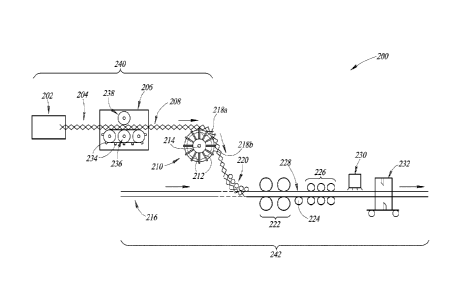
Figure 6 is a schematic view of an assembly line 200 for
fabricating a plurality of varied-length metal studs or an individual stud
having any specified width and any specified length, including any standard
or non-standard width and length. For example, the assembly line 200 can
be used to fabricate a plurality of metal studs having respective lengths that
differ from one another by increments that are less than a pitch of the wire
matrix of the studs, such as by 4 inches or less, 3 inches or less, 2 inches
or less, 1 inch or less, 1/2 inch or less, 1/4 inch or less, 1/8 inch or less,
1/16 inch or less, or by any desired increment.
As illustrated in Figure 6, the assembly line 200 can include
one or more, e.g., one or two, zig-zag wire benders or formers 202. The
zig-zag wire benders 202 can take standard, off-the-shelf linear wire as
input and output two zig-zag wires 204, from which a plurality of angled
continuous wires, such as the first and second angled continuous wires 18
and 20, can eventually be singulated and formed. Thus, the zig-zag wires
204 can have structures matching the structures of the first and second
angled continuous wires 18 and 20, as described above, but in a
continuous form.
The assembly line 200 can also include a first welding system
206, which can include a plurality of spring-loaded pins 234 carried by a
moving conveyor 236, and a rotary resistance welding system 238. The
first welding system 206 can accept the two zig-zag wires 204 as input and
synchronize the movement of the two zig-zag wires 204 by engaging the
pins 234 with apexes of the zig-zag wires 204 and pulling the zig-zag wires
204 taut so that the apexes of the zig-zag wires 204 are spaced apart from
one another by a nominal pitch (e.g., as discussed further below). The first
welding system 206 can also weld (e.g., resistance weld) the two zig-zag
wires 204 to one another at their intersection points, such as by using the
rotary resistance welding system 238, thereby forming a continuous wire
23
CA 03072657 2020-02-11
WO 2019/033197
PCT/CA2018/050901
matrix 208. The zig-zag wires 204 and the continuous wire matrix 208 are
illustrated in Figure 6 as being oriented vertically and within the page for
purposes of illustration, although in practice, the zig-zag wires 204 and the
continuous wire matrix 208 are oriented horizontally and into the page.
The continuous wire matrix 208 can be a continuous wire
matrix from which a plurality of individual wire matrices such as the wire
matrix 16 can eventually be singulated and formed. Thus, the continuous
wire matrix 208 can have a structure matching the structure of the wire
matrix 16, but in a continuous form. For example, the continuous wire
matrix 208 can have a nominal, or un-stretched pitch corresponding to the
pitch P illustrated in Figure 5A, and a nominal, or un-stretched width
corresponding to the width W illustrated in Figure 5A. It has been found
that using a continuous wire matrix 208 having a consistent nominal pitch of
about 6 inches to fabricate metal studs having a variety of specified overall
lengths and widths, and using a continuous wire matrix 208 having a
nominal width that varies based on the specified overall widths of the metal
studs to be fabricated, is advantageous.
The assembly line 200 can also include an expanding
mandrel pitch spacing mechanism, which can be referred to as a first,
upstream conveyor 210. The first, upstream conveyor 210 can include a
plurality of radially extending pins 212, a first encoder 214, and a plurality
of
expanding mandrel segments 218 that can ride radially inward and outward
along the pins 212 between an inner position, designated by reference
numeral 218a and in which the expanding mandrel segments 218 have a
length of 6 inches, and an outer position, designated by reference numeral
218b and in which the expanding mandrel segments 218 have a length of 6
3/8 inches. The radial positions of the expanding mandrel segments 218
can be adjusted along the pins 212 to alter the lengths of the expanding
mandrel segments 218 between the respective pins 212, so that the lengths
of the expanding mandrel segments 218 match the nominal pitch of the
continuous wire matrix 208, and so that the continuous wire matrix 208 can
24
CA 03072657 2020-02-11
WO 2019/033197
PCT/CA2018/050901
be positioned against the expanding mandrel segments 218 as the
continuous wire matrix passes over the first, upstream conveyor 210.
As the continuous wire matrix 208 passes over the first
conveyor 210, the pins 212 can engage with the continuous wire matrix
208, such as by extending through the longitudinal passages extending
through the continuous wire matrix 208 and thereby engaging with the
welded intersections of the continuous wire matrix 208 or with the apexes of
the zig-zag wires 204, to meter the rate at which the continuous wire matrix
208 exits the first conveyor 210 and to prevent the continuous wire matrix
208 from exiting the first conveyor 210 more quickly than desired. In some
cases, this can include applying a force to the continuous wire matrix 208,
e.g., to the welded intersections of the continuous wire matrix 208 or to the
apexes of the zig-zag wires 204, in a direction opposite to the direction the
continuous wire matrix 208 travels through the first conveyor 210 and
through the assembly line 200. In other implementations, the first conveyor
210 can engage with the continuous wire matrix 208 by other techniques,
such as those described below for the second conveyor 226.
The zig-zag wire benders 202, the first welding system 206,
and the first conveyor 210 can be arranged on a first processing line 240
which can be on an elevated mezzanine level on a factory floor.
Continuous elongated channel members 216 can be formed by a sheet
metal roll former located below the elevated mezzanine level on the factory
floor, and can be introduced and metered into the assembly line 200 along
a second processing line 242, located below the elevated mezzanine level
on the factory floor, that runs in parallel to and below the first processing
line 240. In alternative implementations, the second processing line 242
can run above or at the same elevation as and to the side of the first
processing line 240, rather than below the first processing line 240. A
plurality of individual elongated channel members such as the first and
second elongated channel members 12 and 14 can eventually be
singulated and formed from the continuous elongated channel members
CA 03072657 2020-02-11
WO 2019/033197
PCT/CA2018/050901
216. Thus, the continuous elongated channel members 216 can have a
structure matching the structure of the first and second elongated channel
members 12 and 14, but in a continuous form.
The assembly line 200 can also include a plurality of rollers
220 arranged to extend from a last one of the rollers 220 nearest to a
second welding system 222, which can be a resistance welding system,
and which is described further below, and in the second processing line
242, away from the second welding system 222 and toward the first
processing line 240, that is, to extend upstream with respect the assembly
line 200 and upward away from the continuous elongated channel
members 216. Together, the first conveyor 210 and the plurality of rollers
220 form an S-shaped conveyor that precisely guides the continuous wire
matrix 208 along a constant-length path and with minimal friction to reduce
changes to the degree to which the continuous wire matrix 208 is tensioned
or stretched, from the first processing line 240 to the second processing line
242.
The continuous wire matrix 208 travels over the first conveyor
210 and under the plurality of rollers 220 from the first conveyor 210 to the
second welding system 222, from the first processing line 240 into the
second processing line 242, and into physical proximity or engagement with
the continuous elongated channel members 216. The assembly line 200
then carries the continuous wire matrix 208 and the continuous elongated
channel members 216 into the second welding system 222, which can
include a dual-station rotary welding system having powered and spring-
loaded wheels to create a welding pressure to weld (e.g., resistance weld)
apexes of the continuous wire matrix 208 to flanges of the continuous
elongated channel members 216. The second welding system 222 can
weld (e.g., resistance weld) the continuous wire matrix 208 to the
continuous elongated channel members 216, to form a continuous elongate
metal stud 228.
26
CA 03072657 2020-02-11
WO 2019/033197
PCT/CA2018/050901
In doing so, the wheels of the second welding system 222 can
engage with the continuous elongated channel members 216 to weld the
continuous wire matrix 208 thereto, without contacting the continuous
elongate channel members 216 in locations where the continuous wire
matrix 208 is not to be welded thereto. Thus, contact between the wheels
of the second welding system 222 and the continuous elongated channel
members 216 and the continuous wire matrix 208 is intermittent. A plurality
of elongate metal studs, such as metal stud 10, can eventually be
singulated and formed from the continuous elongate metal stud 228. Thus,
the continuous elongate metal stud 228 can have a structure matching the
structure of the metal stud 10, as described above, but in a continuous
form.
The assembly line 200 also includes a second encoder 224
and a second, downstream conveyor 226, which can include a plurality of
pull rolls that engage the continuous elongate metal stud 228, e.g., engage
flanges of the continuous elongated channel members 216 of the
continuous elongate metal stud 228 frictionally or otherwise mechanically,
or by other techniques, such as those described above for the first
conveyor 210, and meter the rate at which the continuous elongate metal
stud 228 exits the second conveyor 226, and to prevent the continuous
elongate metal stud 228 from exiting the second conveyor 226 more slowly
than desired. In some cases, this can include applying a force to the
continuous elongate metal stud 228 in a direction aligned with the direction
the continuous elongate metal stud 228 travels through the second
conveyor 226 and through the assembly line 200.
Thus, the first conveyor 210 can act to hold the continuous
wire matrix 208 back as it travels through the assembly line 200 (e.g., it can
apply a force to the continuous wire matrix 208 that acts in a direction
opposite to its direction of travel, i.e., in an upstream direction), while
the
second conveyor 226 can act to pull the continuous elongate metal stud
228, and thus the wire matrix 208, forward as they travel through the
27
CA 03072657 2020-02-11
WO 2019/033197
PCT/CA2018/050901
assembly line 200 (e.g., it can apply a force to the continuous elongate
metal stud 228 that acts in a direction aligned with its direction of travel,
i.e.,
in an downstream direction). Thus, together, the first conveyor 210 and the
second conveyor 226 can apply tension to the continuous wire matrix 208
such that the continuous wire matrix 208 is stretched, either elastically or
plastically, between the first conveyor 210 and the second conveyor 226,
and held in a tensioned or stretched configuration as it is welded (e.g.,
resistance welded) to the continuous elongated channel members 216.
This can be referred to as "pre-tensioning" the continuous wire matrix 208.
As a result of the stretching, the continuous wire matrix 208
can travel through the first processing line 240 at a first speed, which can
be constant throughout the first processing line 240, and through the
second processing line 242 at a second speed, which can be constant
throughout the second processing line 242. In some cases, such as when
the continuous wire matrix 208 is to be stretched, the second speed is
greater than the first speed. In other cases, such as when the continuous
wire matrix 208 is not to be stretched, the second speed is the same as the
first speed. The first and the second speeds can be between 200 and 300
feet per minute.
Further, by controlling a rate at which the first conveyor 210
meters the continuous wire matrix 208, and by controlling a rate at which
the second conveyor 226 meters the continuous elongate metal stud 228,
the tension developed in the continuous wire matrix 208, and a degree to
which the continuous wire matrix 208 is stretched, can be precisely
controlled. For example, after being stretched, the continuous wire matrix
208 can have a stretched pitch corresponding to the pitch Pa illustrated in
Figure 5B, which is typically greater than the nominal pitch of about 6
inches by the pitch difference Pd illustrated in Figure 5C, and a stretched
width corresponding to the width Wa illustrated in Figure 5B, which is
typically greater than the nominal width by the width difference Wd
28
CA 03072657 2020-02-11
WO 2019/033197
PCT/CA2018/050901
illustrated in Figure 50. In some implementations, the pitch difference Pd
can be anywhere from 0 inches up to at least 3/8 inch.
During operation of the assembly line 200, the first encoder
214 can measure a length of the continuous wire matrix 208 metered out by
the first conveyor 210, such as by counting a number of the welded
intersections of the wires of the wire matrix 208 that pass over the first
conveyor 210. During operation of the assembly line 200, the second
encoder 224 can measure a length of the continuous wire matrix 208
metered into the second conveyor 226, such as by measuring a length of
the continuous elongate metal stud 228 entering into the second conveyor
226. In some cases, the encoders 214 and 224 can be reset every time a
length material corresponding to an individual metal stud is measured by
the encoder 214 or 224, respectively, to reduce or eliminate the
accumulation of measurement errors across a large number of studs.
An output of the first encoder 214 can be compared to an
output of the second encoder 224 to check that the continuous wire matrix
208 is being stretched to a specified degree. If the comparison of these
outputs reveals that the continuous wire matrix 208 is being stretched to the
specified degree, then no corrective action can be taken. If the comparison
of these outputs reveals that the continuous wire matrix 208 is being
stretched to more than the specified degree, then corrective action can be
taken to speed up the first processing line 240 or slow down the second
processing line 242. If the comparison of these outputs reveals that the
continuous wire matrix 208 is being stretched to less than the specified
degree, then corrective action can be taken to slow down the first
processing line 240 or speed up the second processing line 242.
The assembly line 200 can also include a laser scanning
system 230, which can scan the continuous elongate metal stud 228 as it
exits the second conveyor 226. For example, the laser scanner 230 can
scan the continuous elongate metal stud 228 and measure the distance
between adjacent welded intersections of the wires of the wire matrix 208.
29
CA 03072657 2020-02-11
WO 2019/033197
PCT/CA2018/050901
Such distances can be averaged over a length of the continuous elongate
metal stud 228 that corresponds to a length of an individual stud to be
singulated from the continuous elongate metal stud 228, which average can
then be compared to a desired average pitch for the individual stud.
If this comparison reveals that the continuous wire matrix 208
is being stretched to the specified degree, then no corrective action can be
taken. If this comparison reveals that the continuous wire matrix 208 is
being stretched to more than the specified degree, then corrective action
can be taken to speed up the first processing line 240 or slow down the
second processing line 242. If this comparison reveals that the continuous
wire matrix 208 is being stretched to less than the specified degree, then
corrective action can be taken to slow down the first processing line 240 or
speed up the second processing line 242.
The assembly line 200 can also include a flying shear cutting
system 232, which can shear or cut the continuous elongate metal stud 228
in order to singulate and form a plurality of individual metal studs, such as
metal stud 10, from the continuous elongate metal stud 228. Actuation of
the flying shear cutting system 232 to cut the continuous elongate metal
stud 228 can be triggered by a signal provided by the laser scanner 230
that signifies that a desired or specified number of welded intersections of
the wires of the wire matrix 208 have passed by the laser scanner 230.
Upon receipt of such a signal from the laser scanner 230, the
flying shear cutting system 232 can accelerate a cutting unit thereof from a
home position in the direction of travel of the continuous elongate metal
stud 228 until a speed of the cutting unit matches the speed of the
continuous elongate metal stud 228, at which point, the cutting unit can be
actuated to cut the continuous elongate metal stud 228. The cutting unit
can then be decelerated to a stop and then returned to its home position. A
position of the laser scanner 230 can be adjusted and calibrated
experimentally during commissioning of the assembly line 200 until the
cutting unit cuts the continuous elongate metal stud 228 at apexes of the
CA 03072657 2020-02-11
WO 2019/033197
PCT/CA2018/050901
wire matrix 208 to within an accuracy of 0.010 inches. Using the features
described herein, errors affecting this accuracy are not cumulative and thus
the accuracy can remain constant throughout production. In some cases,
such adjusting and calibrating can be performed with a continuous elongate
metal stud 228 having a wire matrix 208 with a pitch of 6 inches, and the
laser scanner 230 can be mounted on a servo-driven positioner so that the
laser scanner 230 can be moved and adjusted as needed during operation
of the assembly line 200 to ensure that the cutting unit cuts individual metal
studs having wire matrices of different pitches at apexes of the wire
matrices.
A method of using the assembly line 200 to fabricate a metal
stud, such as the metal stud 10, to have a specified overall width W,, e.g.,
in a direction from the first major face 30 to the second major face 34, and a
specified overall length L5, e.g., in a direction along the axis 38 in Figure
3,
can include first selecting a specified overall width Ws for the metal stud 10
and a specified overall length L, for the metal stud 10. For example, the
specified overall width Ws can be about 8 inches, about 6 inches, or about 3
5/8 inches, and the specified overall length L5 can be about 8 feet, about 10
feet, or about 12 feet. The method can also include selecting a nominal
pitch for the continuous wire matrix 208, which can be about 6 inches, and
the distance L, as shown in Figure 3.
Once these dimensions have been selected or otherwise
identified, a degree of stretching for the continuous wire matrix 208 can be
determined. For example, it has been found to be advantageous to
manufacture the metal stud 10 so that when the metal stud 10 is fabricated
and singulated, such as by the flying shear cutting system 232, apexes
(e.g., apexes 22a, 22b, 24a, and/or 24b) of the first and second angled
continuous wires 18 and 22 are located at both ends of the metal stud 10
along its length and welded to respective ends of the first and second
elongated channel members 12 and 14 along their lengths, as illustrated in
Figures 1A, 3, and 4.
31
CA 03072657 2020-02-11
WO 2019/033197
PCT/CA2018/050901
Thus, the degree of stretching can be determined so that,
after the continuous wire matrix 208 has been stretched, a first pair of
apexes of the zig-zag wires 204 (e.g., where the first pair of apexes are
diametrically opposed to one another across a width of the zig-zag wires
204) is spaced apart from a second pair of apexes of the zig-zag wires 204
(e.g., where the second pair of apexes are diametrically opposed to one
another across a width of the zig-zag wires 204) by the selected specified
overall length L, for the metal stud 10. Thus, when the continuous elongate
metal stud 228 is singulated by the flying shear cutting system 232, the first
pair of apexes is located at a first end of the singulated metal stud 10, the
second pair of apexes is located at a second end of the singulated metal
stud 10 opposite to its first end, the first pair of apexes is welded to
respective first ends of the singulated channel members 12 and 14, and the
second pair of apexes is welded to respective second ends of the
singulated channel members 12 and 14 opposite to their first ends.
The method can then include determining a nominal width for
the continuous wire matrix 208, which can be configured to facilitate the
assembly of the metal stud 10 to have the selected specified overall width
W. For example, the nominal width can be equal to the specified overall
width Ws, minus the combined thicknesses of the first and second major
faces 30 and 34, minus two times the selected distance L, plus an expected
width difference, corresponding to the width difference Wd, resulting from
the stretching of the continuous wire matrix 208 by the determined degree
of stretching.
The zig-zag wire benders 202 can then form the zig-zag wires
204 such that once they are welded to one another by the first welding
system 206 to form the continuous wire matrix 208, and before the
continuous wire matrix 208 is stretched, the continuous wire matrix 208 has
the selected nominal pitch and the determined nominal width. The first
welding system 206 can then weld the zig-zag wires 204 to one another to
form the continuous wire matrix 208. The first and second conveyors 210,
32
CA 03072657 2020-02-11
WO 2019/033197
PCT/CA2018/050901
226, can then pull on the continuous wire matrix 208 in opposite directions
to stretch the continuous wire matrix 208 by the determined degree of
stretching, either elastically or plastically, and to pull the continuous wire
matrix 208 through the assembly line 200. The first conveyor 210 and the
plurality of rollers 220 can then carry the stretched continuous wire matrix
208 from the first processing line 240 to the second processing line 242 and
into physical proximity and/or engagement with the continuous elongated
channel members 216.
The second welding system 222 can then weld the continuous
wire matrix 208 to the continuous elongated channel members 216, and the
flying shear cutting system 232 can cut the continuous elongate metal stud
228, such as by cutting the continuous elongate metal stud 228 at locations
where the apexes (e.g., the first and second pairs of the apexes) of the
continuous wire matrix 208 are welded to the flanges of the continuous
elongated channel members 216, into individual or singulated metal studs
such as metal stud 10. Such singulated metal studs can have wire
matrices that remains in tension after singulation and even after installation
at a work site. Thus, the methods described herein can result in metal
studs having wire matrices that carry residual stresses after fabrication.
By fabricating the continuous wire matrix 208 to have a
nominal pitch of about 6 inches, and stretching the continuous wire matrix
208 to have a stretched pitch that is greater than the nominal pitch by a
pitch difference of between 0 inches and at least 3/8 inch, the assembly line
200 and the features described herein can be used to fabricate the metal
stud 10 to have apexes of its first and second angled continuous wires 18
and 20 welded to both ends of the first and second elongated channel
members 12 and 14 while having any specified overall length L, above 8
feet.
It has been found that the features described herein can be
used to fabricate a metal stud having a variation in the pitch of its wire
matrix along its length of within the range of 0.062 inches, or in some
33
CA 03072657 2020-02-11
WO 2019/033197
PCT/CA2018/050901
cases within the range of 0.010 inches, and having ends of the first and
second angled continuous wires 18 and 20 coincide with apexes (e.g.,
apexes 22a and 24b or apexes 22b and 24a) of the first and second angled
continuous wires 18 and 20 to within the range of 0.010 inches. Thus, the
features described herein can be used to fabricate a metal stud having an
accuracy of its length of within in the range of 0.040 inches, within in the
range of 0.030 inches, or within in the range of 0.020 inches. It has also
been found that the features described herein can be used to fabricate a
metal stud having a variation in the pitch of its wire matrix along its length
(e.g., a difference between the largest individual pitch and the smallest
individual pitch along the length of the stud) that is relatively large, such
as
at least 1%, at least 2%, at least 3%, at least 4%, or at least 5% of the
average (e.g., mean) pitch of the wire matrix over the length of the stud.
A method of continuously fabricating a plurality of metal studs
using the assembly line 200 can include receiving an order for a plurality of
metal studs having a variety of specific lengths and a variety of specific
widths, such as may be requested by a customer, and selecting the
specified overall width W, and the specified overall length L, for each of the
plurality of metal studs to match the dimensions requested by the customer.
The method can also include continuously fabricating the two zig-zag wires
204, continuously welding the zig-zag wires 204 to one another to
continuously form the continuous wire matrix 208, continuously stretching
the continuous wire matrix 208, continuously forming and introducing the
continuous elongated channel members 216, and continuously welding the
continuous wire matrix 208 to the continuous elongated channel members
216, to continuously form the continuous elongate metal stud 228, in
accordance with the features described above for forming an individual
metal stud.
As the continuous elongate metal stud 228 travels through the
flying shear cutting system 232, the cutting system 232 can cut or singulate
the continuous elongate metal stud 228 into a series of individual metal
34
CA 03072657 2020-02-11
WO 2019/033197
PCT/CA2018/050901
studs, such as a series of metal studs each having the specified overall
length L, and the specified overall width W, for that respective metal stud.
In some cases, the requested stud having the smallest specified degree of
stretching can be the first stud to be formed and singulated, with studs of
the same specified degree of stretching being formed and singulated
immediately thereafter. Once the studs of the smallest specified degree of
stretching have been formed, the assembly line 200 can be adjusted to
fabricate the requested stud having the second smallest specified degree of
stretching. Such an adjustment can be achieved by increasing the forces
the first and second conveyors 210 and 226 exert on the continuous wire
matrix 208 or by increasing the difference in the speeds at which the first
and second processing lines 240 and 242 move the continuous wire matrix
208 through the assembly line 200. Such an adjustment can result in the
fabrication of a transition stud having a wire matrix with two different
pitches, or with a variable pitch, which in some cases may be scrapped,
while in other cases, may be useable as one of the requested studs,
depending on the circumstances.
Once the assembly line 200 has been adjusted, all requested
studs having the second smallest specified degree of stretching can be
fabricated, and the process can be repeated for all of the requested studs.
In other cases, the requested stud having the largest specified degree of
stretching can be the first stud to be formed and singulated, with studs of
deceasing specified degrees of stretching being formed and singulated
thereafter, until all of the requested studs have been fabricated.
Adjustments of the assembly line 200 can be achieved in such cases by
decreasing the forces the first and second conveyors 210 and 226 exert on
the continuous wire matrix 208 or by decreasing the difference in the
speeds at which the first and second processing lines 240 and 242 move
the continuous wire matrix 208 through the assembly line 200.
In some cases, the requested stud having the smallest
specified overall length L, and/or the smallest specified overall width W,
CA 03072657 2020-02-11
WO 2019/033197
PCT/CA2018/050901
can be the first stud to be formed and singulated, with studs of the same
specified overall length L, and/or the same specified overall width W, being
formed and singulated immediately thereafter. The assembly line 200 can
then be adjusted to fabricate the requested stud having the second smallest
specified overall length L, and/or the second smallest specified overall
width Ws, such as by adjusting the operation of the first and second
conveyors 210, 226 to adjust the assembly line 200 to fabricate a stud
having a larger specified overall length L5, by adjusting the operation of the
flying shear cutting system 232 to cut studs having a larger specified overall
length L5, and/or by adjusting the zig-zag wire benders 202 to adjust the
assembly line 200 to fabricate a stud having a larger specified overall width
W. The process can be repeated for all of the requested studs. In other
cases, the requested stud having the largest specified overall length Ls,
and/or the largest specified overall width W, can be the first stud to be
formed and singulated, with studs of deceasing dimensions being formed
and singulated thereafter, until all of the requested studs have been
fabricated.
As described above, the features described herein can be
used to fabricate the metal stud 10 to have apexes of its first and second
angled continuous wires 18 and 20 welded to both ends of the first and
second elongated channel members 12 and 14 while having any specified
overall length L5 above 8 feet. Such results provide important advantages.
For example, by manufacturing metal studs to specific lengths in a factory
setting, the need to cut or trim studs to length during installation can be
reduced or eliminated, improving installation efficiency.
Further, fabricating metal studs such as metal stud 10 to have
apexes of its first and second angled continuous wires 18 and 20 welded to
both ends of the first and second elongated channel members 12 and 14
makes the metal stud 10 symmetrical, so that installers can install the stud
10 without regard to which end of the stud is the top or the bottom end of
the stud 10, eliminates the sharp ends of the wires 18 and 20 that would
36
CA 03072657 2020-02-11
WO 2019/033197
PCT/CA2018/050901
otherwise pose hazards during installation, and increases web crippling
strengths of the stud 10 at its respective ends. Further, fabricating metal
studs such as metal stud 10 to have apexes of its first and second angled
continuous wires 18 and 20 welded to both ends of the first and second
elongated channel members 12 and 14 facilitates installation of a series of
metal studs so that the passages 28 are aligned, or at least more closely
aligned, across the series of metal studs.
Figures 7-11 show a reinforcement plate 600 for use with the
metal stud to fabricate a metal framing member 1100 (Figures 12-16),
according to at least one illustrated embodiment. In particular, Figure 11
shows the reinforcement plate 600 in a flattened or unfolded configuration,
while Figures 7-10 show the reinforcement plate 600 in a folded
configuration.
The reinforcement plate 600 may have a rectangular profile,
having a length Lp and a width Wp, and having a gauge or thickness of
material G that is generally perpendicular to the profile and hence the
length Lp and the width W. The reinforcement plate 600 has a first pair of
opposed edges 602a, 602b, a second edge 602b of the first pair opposed
to a first edge 602a of the first pair across the length Lp of the
reinforcement
plate 600. The reinforcement plate 600 has a second pair of opposed
edges 604a, 604b, a second edge 604b of the second pair opposed to a
first edge 604a of the second pair across the width Wp of the reinforcement
plate 600.
Between the first and the second pair of opposed edges 602a,
602b, 604a, 604b is a center or plate portion 606 of the reinforcement plate
600. The center or plate portion 606 of the reinforcement plate 600 is
preferably corrugated, having a plurality of ridges 608a and valleys 608b
(only one of each called out for clarity of illustration), the ridges 608a and
valleys 608b which extend between the first and the second edges 602a,
602b of the first pair of opposed edges, that is across the length Lp of the
reinforcement plate 600. The ridges 608a and valleys 608b preferably
37
CA 03072657 2020-02-11
WO 2019/033197
PCT/CA2018/050901
repeat in a direction along which the first and the second edges 602a, 602b
extend, that is repeating along the width Wp of the reinforcement plate 600.
The corrugations provide structural rigidity to the reinforcement plate 600.
The pattern may be continuous, or as illustrated may be discontinuous, for
example omitting ridges 608a and valleys 608b in sections between pairs of
opposed tabs (e.g., opposed pair of tabs 610a, 612a, and opposed pair of
tabs 610b, 612b).
While first and second edges 602a, 602b are illustrated as
straight edges that extend in a straight line between opposed edges 604a,
604b, the first and second edges 602a, 602b can advantageously be
notched or serrated to minimize contact between the first and second
edges 602a, 602b and the elongated channel members 12, 14, with contact
limited to only a few portions that are fastened or secured directly to the
channel members 12, 14, thereby reducing heat transfer.
The reinforcement plate 600 has at least one upstanding
portion 610a-610b along the first edge 602a and at least one upstanding
portion 612a-612b along the second edge 602b. The upstanding portions
610a, 610b may take the form of a respective pair of tabs that extend
perpendicularly from the plate portion 606 along the first edge 602a and a
respective pair of tabs that extend perpendicularly from the plate portion
606 along the second edge 602b.
As illustrated in Figures 12-16, the reinforcement plate 600
can be physically secured to the metal stud 10 via the at least one
upstanding portion 610a, 610b along the first edge 602a and the at least
one upstanding portion 612a, 612b along the second edge 602b. For
example, the reinforcement plate 600 can be welded by welds to the metal
stud 10 via the tabs 610a, 610b, 612a, 612b that extend perpendicularly
from the plate portion 606. For instance, a first set of welds can physically
secure the respective pair of tabs 610a, 610b that extend perpendicularly
from the plate portion 606 along the first edge 602a to the first flange 32 of
the first elongated channel member 12, and a second set of welds can
38
CA 03072657 2020-02-11
WO 2019/033197
PCT/CA2018/050901
physically secure the respective pair of tabs 612a, 612b that extend
perpendicularly from the plate portion 606 along the second edge 602b to
the first flange 36 of the second elongated channel member 14.
The reinforcement plate 600 can be physically secured to the
metal stud 10 so that the edges 602a, 602b of the reinforcement plate 600
are within and enclosed by the first and second elongated channels 12 and
14. For example, the first edge 602a can be positioned adjacent the major
face 30 and between the flanges 32 and 42, and the second edge 602b can
be positioned adjacent the major face 34 and between the flanges 36 and
44. In such an embodiment, the reinforcement plate 600 can be adjacent
to, abutting, and in contact with the wire matrix 16, and can be within or on
the inside of the metal stud 10.
In various embodiments, the reinforcement plate 600 can be
physically secured, connected, fixed, or coupled to the other components of
the metal stud 10 using any suitable mechanisms, methods, fasteners, or
adhesives. For example, the reinforcement plate 600 can be physically
secured to the other components of the metal stud 10 by an interference fit
between the first and second elongated channel members 12, 14, such as
between their respective major faces 30 and 34. In such an example, the
length Lp of the reinforcement plate 600 can be slightly larger than a
distance between the major faces 30 and 34, so that the reinforcement
plate 600 is secured by an interference fit between the major faces 30, 34
when positioned between them.
As another example, the reinforcement plate 600 can be
resistance welded to the other components of the metal stud 10. In such
an example, the tabs 610a, 610b, 612a, and 612b of the reinforcement
plate 600 can be resistance welded to the major faces 30 and 34, or the
center or plate portion 606 of the reinforcement plate 600 can be resistance
welded to the flanges 32 and 36 or to the wire matrix 16. As yet another
example, the reinforcement plate 600 can be secured to the other
components of the metal stud 10 by swaging or radially cold expanding a
39
CA 03072657 2020-02-11
WO 2019/033197
PCT/CA2018/050901
bushing or bushing assembly via passage of a tapered mandrel, where the
bushing extends through aligned apertures or openings formed in the major
faces 30 and 34 and the tabs 610a, 610b, 612a, and 612b. For example,
Figure 17 illustrates a bushing assembly 702 that extends through aligned
apertures in the tab 610a and the major face 30, and that has been swaged
or radially cold expanded to secure the tab 610a to the major face 30. As
yet another example, the reinforcement plate 600 can be secured to the
other components of the metal stud 10 by rivets extending through aligned
apertures or openings formed in the major faces 30 and 34 and the tabs
610a, 610b, 612a, and 612b. For example, Figure 18 illustrates a rivet 708
that extends through aligned apertures in the tab 610a and the major face
30, and that has been used to secure the tab 610a to the major face 30.
As another example, the reinforcement plate 600 can be
physically secured to the other components of the metal stud 10 by
clinching or press joining the reinforcement plate 600 to the first and second
elongated channel members 12 and 14. In such an example, the tabs
610a, 610b, 612a, and 612b of the reinforcement plate 600 can be clinched
to the major faces 30 and 34 of the elongated channel members 12 and 14,
or the center or plate portion 606 of the reinforcement plate 600 can be
clinched to the flanges 32 and 36 of the elongated channel members 12
and 14. For example, Figure 19A illustrates the tab 610a being positioned
adjacent to the major face 30 in preparation for a clinching operation, and
Figure 19B illustrates the tab 610a clinched to the major face 30 after the
clinching operation is complete. The clinching operation can use a punch
to press and deform the tab 610a and major face 30 at a location indicated
by reference numeral 704 to form an interlocking structure indicated by
reference numeral 706 to lock the tab 610a to the major face 30. Additional
information regarding clinching operations can be found in U.S. Patent Nos.
8,650,730, 7,694,399, 7,003,861, 6,785,959, 6,115,898, and 5,984,563,
and U.S. Pub. Nos. 2015/0266080 and 2012/0117773, all of which are
assigned to BTM Corporation.
A first reinforcement plate 600 may be fixed at least proximate
or even at a first end of the metal stud 10, and a second reinforcement
plate 600 may be fixed at least proximate or even at a second end of the
same metal stud 10. The first and second reinforcement plates 600 can be
coupled to the other components of the metal stud 10 by any of the
mechanisms, methods, fasteners, or adhesives described herein. The first
and second reinforcement plates 600 can be coupled to the other
components of the metal stud 10 by the same or by different mechanisms,
methods, fasteners, or adhesives.
Those of skill in the art will recognize that many of the
methods set out herein may employ additional acts, may omit some acts,
and/or may execute acts in a different order than specified.
The various embodiments described above can be combined
to provide further embodiments. These and other changes can be made to
the embodiments in light of the above-detailed description. In general, in
the following claims, the terms used should not be construed to limit the
claims to the specific embodiments disclosed in the specification and the
claims, but should be construed to include all possible embodiments along
with the full scope of equivalents to which such claims are entitled.
Accordingly, the claims are not limited by the disclosure.
41
Date Recue/Date Received 2021-07-23