Note: Descriptions are shown in the official language in which they were submitted.
Child Safety Seat
Disclosed is a child safety seat and a system comprising a vehicle and a child
safety seat.
Child safety seats are secured to vehicles through different systems. One
system is the three-point belt, which has a seatbelt tongue that can be
inserted into a buckle positioned in the car and which is typically fixed to
the
child safety seat at various points. Another possibility is given by the
ISOFIX
system, which is an international standard for attachment points for child
safety seats in passenger cars. The principle of the ISOFIX connection is a
locking mechanism which has a hook trap "ISOFIX attachment" for releasably
locking the seat to a respective bar "anchorage" that is fixed to the vehicle.
The ISOFIX system uses two respective locking mechanisms typically having
a center-to-center distance between the respectively used hooks of 280mm.
The "anchorage" means one 6 mm diameter rigid round horizontal bar,
extending from vehicle or seat structure to accept and restrain an ISOFIX
Child Restraint System with ISOFIX attachments.
Summary
Disclosed is a child safety seat comprising at least a first, a second and a
third
locking mechanism, each being adapted for releasably locking the seat to a
vehicle at a respective anchorage point, wherein the anchorage points of the
first locking mechanism and the second locking mechanism are arranged on a
line, and the anchorage point of the third locking mechanism is spaced apart
from the line. The child safety seat further comprises a seat surface of the
seat, the seat surface providing a seating area of the seat. It is within the
scope of the invention that the third locking mechanism is adjustable in
height
relative to the seat surface. Further, the child safety seat comprises a
coupling
member, the third locking mechanism being secured to the seat via the
coupling member, the coupling member being height adjustable to enable the
height adjustability of the third locking mechanism.
1
3752871
CA 3073145 2020-02-19
Embodiments may have the benefit that child safety seats can be secured to
vehicles in a very safe manner because of the usage of the three anchorage
points spaced apart from each other. In case of a crash, a rotation of the
seat
about a single axis or line may thereby be avoided due to the three anchorage
points.
It has to be noted that generally the vehicle may be any vehicle which may
carry the child safety seat, including cars, trucks, boats, trains or
airplanes.
Typically, the child safety seat may be attached to a seat of the vehicle
which
comprises the respective three anchorage points. For example, the first and
the second locking mechanisms are making use of or are based on the
conventional ISOFIX locking mechanism (or ISOFIX attachments), adapted to
engage with the respective anchorage points which are arranged on a line
behind the area of the inflection point in which the seat surface of the
vehicle
seat merges with the seat backrest of the vehicle seat on which the child
safety seat is to be installed.
Generally, the first, second and third locking mechanisms may be identical.
Therefore, any further discussions made with respect to the third locking
mechanism may also apply analogously to the first and second locking
mechanisms and vice versa. However, the third locking mechanism may be
different from the first and second locking mechanisms. The third locking
mechanism may be a type of locking mechanism to stiffly, rigidly and
releasably fix a child safety seat to a vehicle seat.
It further has to be noted that for the ISOFIX system the anchorages are
typically 6 mm diameter transverse horizontal rigid bars which cover two
zones of 25 mm minimum effective length located on the same axis. In this
example, the anchorage points of the first locking mechanism and the second
locking mechanism are arranged on the line provided by this axis.
2
3752871
CA 3073145 2020-02-19
In accordance with the invention, the child safety seat further comprises a
seat surface of the seat, the seat surface providing a seating area of the
seat.
For example, the above-mentioned line may run below the seat surface. In a
further example, the child safety seat further comprises a backrest and a
supporting base, the supporting base supporting the seat surface and the
supporting base or the backrest comprising the third locking mechanism.
It is possible that the third locking mechanism provides a stiff and rigid
coupling of the child safety seat to the vehicle seat on which the child
safety
seat is to be mounted, i.e., installed using the first, second and third
locking
mechanisms. It may be assumed that in the future, the mechanical stability of
vehicle seats that are available to accommodate adult passengers will be
enhanced up to the scenario in which the vehicle seats themselves comprise
the vehicle seatbelt, for example the three-point seatbelt. The integration of
the vehicle seatbelt into the seat may be of significant relevance in the case
of
autonomous or automated vehicles and automated driving, where passenger
orientation in the direction of vehicle movement may not be necessary
anymore ¨ the vehicle can drive by itself, and any passengers in the vehicle
may be oriented in an arbitrary direction since there is no need anymore to
control or "drive" the vehicle as in the past.
Further, the third locking mechanism is adjustable in height relative to the
seating surface. This may have the benefit that the conventional attachments
(e.g., from the ISOFIX system) using the first and second locking mechanisms
can remain unchanged while, depending on the size of the child safety seat
and the width of the vehicle seat to which the child safety seat is to be
attached, the third locking mechanism can be adjusted in height in a flexible
manner.
In addition, the child safety seat further comprises a coupling member, the
third locking mechanism being secured to the child safety seat via the
coupling member, the coupling member being height adjustable to enable the
height adjustability of the third locking mechanism. The coupling member may
be a stiff and rigid coupling member. Further, the third locking mechanism
3
3752871
CA 3073145 2020-02-19
may be pivoted to the coupling member. For example, the third locking
mechanism is pivoted to the coupling member. For example, the coupling
member comprises an axis, and the third locking mechanism is pivoted to the
shell of the child safety seat by the axis. The provision for the possibility
of
pivoting the third locking mechanism may have the benefit of simplifying
installation of the child safety seat in the vehicle. For a safe installation
of the
child safety seat, there may be no need to exactly position the third locking
mechanism relative in height with respect to the vehicle counterpart
(typically
an axis "anchorage point") to which the third locking mechanism is able to
lock). Eventual inaccuracies in height positioning of the third locking
mechanism may therefore be easily compensated for by means of pivoting the
third locking mechanism relative to the coupling member.
In accordance with an embodiment, the anchorage point of the third
mechanism is centered with respect to the width of the child safety seat. This
may have the benefit that in the case of a crash, forces acting on the child
safety seat are equally distributed over the seat. This may minimize the risk
that during a crash one side of the seat is subjected to greater stress than
the
other side due to lifting forces that may exist in case of a non-centered
arrangement of the third locking mechanism with respect to the width of the
child safety seat.
In accordance with an embodiment, the third locking mechanism is adapted
for enabling the releasable locking of the child safety seat to the vehicle in
a
functioning position of the third locking mechanism, the pivoting of the third
locking mechanism being such that the third locking mechanism can be
pivoted between the functioning position and a resting position, wherein in
the
resting position of the third locking mechanism is received within the shell
of
the seat. The third locking mechanism may be arranged at the height of the
center of gravity +1- 10cm of the child seat. For example, in the resting
position the third locking mechanism is received within the backrest itself.
The
third locking mechanism may be received in the supporting base alternatively
or additionally. This may have the benefit that in case the child safety seat
is
used in vehicles that have no counterpart for locking the third locking
4
3752871
CA 3073145 2020-02-19
mechanism to the vehicle, the child safety seat may nevertheless be used
without the risk that, due to the presence of the third locking mechanism
protruding from the child safety seat, the child safety seat damages the
vehicle seat on which the child safety seat is to be installed. Further, while
hand-carrying of the child safety seat, risk of injury due to protruding parts
of
the third locking mechanism is minimized.
In accordance with an embodiment, the coupling member is an elongate
component pointing downwards from the seat surface, wherein for example
the elongate component is pivoted to the supporting base. The term
"downwards" is understood as pointing away from the seating surface of the
child safety seat in a direction that is on a side of the seating surface
opposite
the head area of the child safety seat. This may have the benefit that in case
of an installation of the child safety seat on a vehicle seat, a fixation of
the
child safety seat to the front face area of the vehicle seat is possible in a
convenient manner. At any time, the third locking mechanism is accessible
from the front side of the vehicle seat (knee or foot area of the seat) for
releasably locking the locking mechanism to the vehicle. In other words, this
could ensure that the third locking mechanism is accessible at all times from
the footwell of the vehicle seat so that the third locking mechanism can be
conveniently operated. Again, due to the fact that the elongate component is
pivoted to the supporting base, a convenient flexibility may be given to the
user when installing the child safety seat in the vehicle since small
differences
in height between the third locking mechanism and the respective vehicle's
fixed counterpart may be compensated for easily.
In accordance with an embodiment, the child safety seat further comprises a
guiderail, the third locking mechanism being secured to the child safety seat
via the guiderail and the guiderail being adjustable in length. By means of
such a guiderail, the distance between parts of the child safety seat and the
vehicle seat on which the child safety seat is to be installed may be varied
freely. For example, if the backrest inclination of the vehicle seat on which
the
child safety seat is to be installed can be varied, the different backrest
5
3752871
CA 3073145 2020-02-19
inclination can be taken into account via a distance variation in the
guiderail
without having to change the position of the child safety seat itself.
For example, due to the guiderail's adjustability in length, the spacing
between
the backrest of the child safety seat and the anchorage point of the third
locking mechanism is adjustable in case the backrest comprises the third
locking mechanism. It has to be noted here that one may denote this spacing
as "dorsal" spacing since from an anatomical point of view of a child being
seated in the child safety seat, the dorsal spacing is the spacing behind the
child's back between the backrest and the anchorage point on the back side
of the child safety seat.
In a further example, due to the guiderail's adjustability in length, the
spacing
between the backrest of the child safety seat and the anchorage point of the
third locking mechanism is adjustable in case the supporting base comprises
the third locking mechanism. The latter spacing may be considered "ventral"
spacing between the backrest and the anchorage point since the term ventral
refers to the front side of the child (the direction pointing away from the
child's
chest) that is to be seated in the child safety seat, i.e., it refers to a
direction
facing away from the front side of the child.
In accordance with an embodiment, the guiderail is a telescopic rail, wherein
more particularly it comprises a first and a second rail engaging each other,
the first rail being attached to the child safety seat, e.g., via the coupling
member, and the third locking mechanism being pivoted to the second rail,
wherein the first and the second rail comprise multiple opposing latching
elements. The usage of a telescopic rail may have the benefit that in a space-
saving manner, a large variability in guiderail length can be implemented in
the child safety seat. In a sense, a compact and highly flexible positioning
of
the child safety seat in the vehicle may be possible.
For example, the third locking mechanism is pivoted to the guiderail, e.g. by
an axis. For example, the third locking mechanism is mounted on the guiderail
in such a manner that it can be tilted relative to the guide rail. This may
6
3752871
CA 3073145 2020-02-19
provide additional flexibility in using the third locking mechanism when
installing the child safety seat in the vehicle since, due to the pivoting of
the
third locking mechanism to the guiderail, different height positions of the
respective vehicle counterpart to which the third locking mechanism is to be
locked can be accounted for. The same holds with respect to different
backrest inclinations of the seat on which the child safety seat is to be
installed in the vehicle.
In accordance with an embodiment, the third locking mechanism comprises a
hook trap for releasably locking the child safety seat to the vehicle. The
principle of a hook trap is as follows: when moving toward a corresponding
crossbeam or bar located in the vehicle at the respective anchorage point, the
hook trap can first run diagonally upwards over the crossbeam and then, after
the end of the hook has crossed the crossbeam, fall downwards 'into the lock'.
The hook now ensures that it is no longer possible to remove the hook from
the crossbeam without lifting the hook again using, e.g., a respective release
mechanism.
In accordance with an embodiment, the child safety seat further comprises a
release button adapted for releasing the locking of the third locking
mechanism when the button is actuated. This is an example of such a release
mechanism.
For example, the backrest of the child safety seat comprises a release button.
For example, the release button may be comprised or contained in a sidewall
of the backrest or it may be comprised or contained in an upper outer edge of
the sidewall, e.g., centered with respect to the width of the seat. This may
have the benefit that the operation of the release button is comfortable for a
user.
In accordance with an embodiment, the child safety seat further comprises a
rebound bar arranged at the supporting base, the foot end or the head end of
the seat, the rebound bar being adapted for being fixed rigidly to the seat
and
for forming an abutment with respect to the vehicle above the seat surface,
7
3752871
CA 3073145 2020-02-19
and comprising the third locking mechanism and the release button.
Generally, "rebound" is understood as the movement that occurs in response
to the initial action of a crash; i.e., in the event of a crash, there are
always
two forces impacting on the child located in the child safety seat, the
initial
crash force and the subsequent rebound. The rebound bar is typically resting
against the backrest of the vehicle seat when the child safety seat is
installed
on the vehicle seat. By means of the rebound bar, the rebound movement of
the child safety seat is reduced in the event of a crash. Another benefit of
the
rebound bar is that in case of rear impact onto the vehicle in which the child
safety system is installed, a rotation of the child safety seat to the rear
direction is also controlled.
Since the rebound bar comprises the third locking mechanism and optionally
the release button, this may be beneficial because no extra rigid connection
means are required to attach the third locking mechanism to the child safety
seat. Due to the purpose of the rebound bar to prevent a rebound of the child
safety seat in case of a crash, the rebound bar is typically made very
mechanically stable and rigid and therefore provides a decent attachment
point for the third locking mechanism.
In accordance with an embodiment, the rebound bar is arranged on the seat
so as to be rotatable about an axis and be releasably fixable in a plurality
of
positions, wherein more particularly the release button is further adapted to
release the fixing of the rebound bar when actuated (fixing of the rebound bar
in a desired rotational position). For example, the rebound bar may be
inclined
with respect to the seating surface of the child safety seat such that it is
adapted to the inclination of the backrest of the vehicle seat on which the
child
safety seat is to be installed. By means of the adjustable inclination of the
rebound bar, it is possible to take various inclinations of vehicle seat
backrests
into account and to minimize or avoid any distance between the rebound bar
and the backrest of the vehicle seat on which the child safety seat is to be
installed. Since the release button is adapted to both releasing the fixing of
the rebound bar and the third locking mechanism, easy removal of the child
safety seat from the vehicle is possible, thereby minimizing the number of
8
3752871
CA 3073145 2020-02-19
required manipulations. After the rebound bar is adjusted regarding its
inclination as desired, the release button may be used to fix the rebound bar
to this inclination angle. The release button may be for example a button that
releases the fixation while the button is being operated and that leads to a
fixation of the rebound bar to its desired position when the button is
released
again. Thus, the rebound bar can be adjusted to the backrest of the vehicle
seat.
For example, the release button has a child lock adapted to prevent operation
of the release button by the child. This may be especially helpful in case the
rebound bar is arranged at the foot end of the seat, i.e., in case the child
safety seat is to be installed with the child being oriented in the vehicle in
a
rearward direction. In this case, the child may unintentionally have access to
the release button when facing the rebound bar and thus the release button.
The child lock may prevent unwanted operation of the release button. The
child lock may be provided in different manners; e.g., it might foresee
specific
force requirements for operation such that the release button may only be
operated by an adult but not by an child because the child does not have the
strength to operate the release button. Other possibilities include the usage
of
a child lock which can only be operated by simultaneously performing two
independent unlock operations, such as the necessity to operate or move a
safety button before being able to operate the release button itself, etc.
In accordance with an embodiment, the elongate component comprises the
release button, the release button being arranged on the elongate component
for being operable from the side of the elongate component facing away from
the line on which the anchorage points of the first and second locking
mechanism are arranged. This may have the benefit that the release button is
operable in a very convenient manner. In case the elongate component is on
the supporting base pointing downwards, the third locking mechanism may
engage with a respective counterpart of the vehicle that is located below the
seating surface provided by the vehicle seat on which the child safety seat is
to be installed. Since the release button is arranged on the elongate
component for being operable from the side of the elongate component facing
9
3752871
CA 3073145 2020-02-19
away from the line, an operation of the release button from the front and the
foot well of the vehicle seat on which the child safety seat is to be
installed
may be possible in a convenient manner.
In another aspect, the invention relates to a system comprising a vehicle and
a child safety seat as described above. The vehicle has respective
counterparts to which the first, second and third locking mechanisms may
releasably lock. The above-described examples and embodiments may be
combined freely as long as the individual examples and embodiments are not
mutually exclusive.
The connection between the third locking mechanism and the rigid structure of
the child safety seat may be either rigid or soft. For example, the third
locking
mechanism may be fixed to the structure of the child safety seat via either a
strap or the above-described coupling member, elongate component and/or
guiderail, each optionally via respective optional pivoting elements.
It has to be noted that any of the above-described locking mechanisms may
comprise sensors or indicators for informing a user of the child safety seat
(i.e., the adult) on correct or insufficient installation. For example, a
color
indicator may be provided on the locking mechanisms, which indicates for
example in red and green whether the respective locking mechanism is
correctly engaged with the respective counterpart of the vehicle seat. Either
via wireless or wired communication connections, the locking mechanisms
may also communicate their locking state or installation state
(correct/insufficient) to a vehicle electronic system or to a mobile
telecommunication device that runs a respective monitoring application. In
either case, a user of the vehicle in which the child safety seat is installed
can
be informed about a correct/incorrect, sufficient/insufficient installation of
the
child safety seat.
It has to be noted that instead or additionally to the color indicator other
indicator means may be used including an acoustic or haptic indicator. An
3752871
CA 3073145 2020-02-19
acoustic indicator may provide a sound like a "click" or another signal tone,
indicating a correct installation state or locking state.
It may also be possible that various components of the child safety seat are
communicatively coupled to a collision avoidance system of the vehicle. A
collision avoidance system is also known as a pre-crash system, forward
collision warning system or collision mitigation system, designed to
autonomously take action to reduce the severity of a collision in case a
collision cannot be avoided. Typically, collision avoidance systems or pre-
crash systems autonomously operate car brakes, close windows, pre-tension
safety belts, bring backrests of passenger seats to an upright position, etc.
For example, given a height adjustability of the third locking mechanism via
the coupling member or a length adjustability via the guiderail, the signal of
an
immediately impending crash (pre-crash signal) may be used to adjust the
position of the child safety seat relative to the vehicle seat on which the
child
safety seat is installed. For example, the length and/or height adjustability
of
the third locking mechanism may be used to pull the child safety seat tighter
and closer to the vehicle seat. This may minimize the spring effect due to the
typically soft surface of the vehicle seat on which the child safety seat is
installed and thus also minimize the respective rebound that partially occurs
due to the spring effect during the crash. In another example, the height and
length adjustability of the third locking mechanism may be used to rotate the
seating surface of the child safety seat around the line formed by the
anchorage points of the first and second locking mechanisms.
In case the child safety seat is mounted in the vehicle in a forward-facing
direction, this leads to a backward tilting of the child to be accommodated in
the child safety seat. As a consequence, this increases the angle between the
road surface on which the vehicle moves and the seat surface of the child
safety seat. Forces acting on a child in the seat are therefore concentrated
more on the child's torso, and the danger of a tilting movement of the child's
head during the crash can be minimized. In the event that the discussed seat
inclination of the child safety seat can be adjusted by means other than the
11
3752871
CA 3073145 2020-02-19
adjustable third locking mechanism, these other means can also be controlled
by the pre-crash signal that is communicated in the event of an unavoidable
crash to move the seat to a certain desired position. Generally, the rotation
of
the seat backwards may minimizing both head excursion and loads acting on
child.
In another example, in case the child safety seat is installed in rear facing
mode in the vehicle (child to be accommodated in the seat facing in rearward
direction of the vehicle), the length and/or height adjustability of the third
locking mechanism may be used based on the signal indicating an
immediately impeding frontal impact onto the vehicle to rotate the seating
surface of the child safety seat around the line formed by the anchorage
points of the first and second locking mechanisms towards the back of the
vehicle. This moves the face of the child farther away from the front side of
the
vehicle which may improve the protection of the child in the child safety
seat.
This also holds true with respect to the first and second locking mechanisms,
which may also be adjustable in height and/or length and which may
analogously be controlled by the pre-crash signal, as discussed above with
respect to the third locking mechanism.
It further has to be mentioned that the principles discussed above with
respect
to the third locking mechanism may equally be applied to the first and second
locking mechanisms. In the following, embodiments of the invention are
described in greater detail in which:
Fig. 1 shows a schematic side view of a child safety seat installed
in a
forward-facing direction,
Fig. 2 is a schematic side view of a child safety seat also installed in a
forward-facing direction,
Fig. 3 is a perspective view of the child safety seat of Fig. 2,
12
3752871
CA 3073145 2020-02-19
Fig. 4 is a perspective view of a locking mechanism arranged on a
guiderail,
Fig. 5 is a schematic side view of a child safety seat installed in
a
rearward-facing direction,
Fig. 6 is a perspective view of the child safety seat of Fig. 5,
Fig. 7 illustrates a schematic side view of a further child safety
seat
installed in a rearward-facing direction,
Fig. 8 is a perspective view of the child safety seat of Fig. 7,
Fig. 9 illustrates a further perspective view of a child safety
seat
installed in a rearward-facing direction.
In the following, similar elements are denoted by the same reference
numerals.
Fig. 1 is a schematic side view of a child safety seat 100 installed on a
vehicle
seat 102. The child safety seat in the present example is a newborn or infant
car seat having a seating surface 101 (indicated by the dashed line) and a
backrest 111. The seating surface and the backrest are mounted on a seat
base 108. Further illustrated in Fig. 1 is an ISOFIX locking mechanism 104
that is installed on the seat base 108 on the left and right side (only right
side
currently visible) of the child safety seat 100. The anchorage point at which
the ISOFIX locking mechanism locks the child safety seat 100 to the vehicle
seat 102 is in the present example in the very lower end of the backrest of
the
vehicle seat 102.
The child safety seat 100 is installed in a forward-facing direction such that
the
back of the child to be accommodated in the seat and therefore the backrest
111 are pointing toward the backrest of the vehicle seat 102. The supporting
base 108 has a rebound bar 500 extending from the supporting base 108 in
13
3752871
CA 3073145 2020-02-19
an upward direction in between the backrest 111 of the child safety seat and
the backrest of the vehicle seat 102. The rebound bar 500 is optional. The
rebound bar 500 carries in the present example a locking mechanism 106 that
may operate based on the same principles as the ISOFIX connectors 104.
The backrest of the vehicle seat 102 has a recess 112 which comprises a
counterpart portion, e.g., a locking bar, with which the locking mechanism 106
may engage. In case of engagement, the child safety seat 100 is locked to the
vehicle seat 102 using the two ISOFIX connectors 104 and the locking
mechanism 106. As indicated, the third locking mechanism 106 may be
arranged at the height of the center of gravity +1- 10cm of the child seat
100.
It has to be noted that even though throughout the present disclosure the
locking mechanism 104 is described as an ISOFIX locking mechanism, it is to
be understood that any other type of locking mechanism to rigidly and
releasably fix the child safety seat 100 to the vehicle seat 102 is also
possible.
Therefore, the designation of the locking mechanism 104 as "ISOFIX
connection" is not to be considered and understood in a limiting manner.
The two ISOFIX locking mechanisms 104 provide for a locking of the child
safety seat 100 to anchorage points that are arranged on a line 114, wherein
in Fig. 1 this line is perpendicular to the drawing plane of Fig. 1. The
locking
mechanism 106 is spaced apart from that line 114, which has the effect that
any rotational movement around the frictional axis 114 due to an acceleration
of the child safety seat, for example due to a braking action of the vehicle
in
which the seat is installed, is prohibited.
A release button 110 may be provided on both the ISOFIX connectors 104
and the locking mechanism 106. By means of operation of the release button
110, the fixation of the ISOFIX connectors 104 and the locking mechanism
106 may be released.
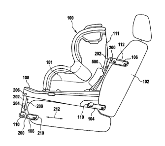
Fig. 2 shows a side view of a child safety seat 100 which has a similar
configuration as the child safety seat of Fig. 1. However, additionally, a
locking
mechanism 106 is shown at the foot end of the child safety seat which locks
14
3752871
CA 3073145 2020-02-19
with a respective counterpart, e.g., a locking bar that is located in a recess
210 of the lower seat portion of the vehicle seat 102. It has to be noted that
typically, besides the ISOFIX connectors 104, only a single locking
mechanism 106 either at the foot end or at the backrest of the child safety
seat may be required and used. Therefore, any explanations given with
respect to the combination of two locking mechanisms 106 also holds in case
only a single locking mechanism 106 is used.
The locking mechanism 106 at the foot end of the child safety seat is mounted
to the seat base 108 through an elongate component 202 pointing downwards
from the seat surface 101. The elongate component 202 is pivoted to the
supporting base 108 using an axis 206. An operating button 204 is provided
on the elongate component 202, which permits adjustment of the length of the
elongate component, i.e., to move the locking mechanism 106 up and down in
direction 208. By means of the movement, the locking mechanism 106 can be
moved relative to the lower seating portion of the vehicle seat 102 in order
to
smoothly slide into the recess 210.
The locking mechanism 106 may also be pivoted via a respective axis 200 to
the elongate component 202, and optionally the locking mechanism 106 is
adjustable in length in direction 212.
Similar to the height adjustability of the locking mechanism 106 at the foot
end
of the child safety seat 100, the locking mechanism 106 mounted either at the
backrest 111 or, in the example of Fig. 2, mounted at the rebound bar 500,
may also be adjustable in height relative to the seating surface 101. For this
purpose, the locking mechanism 106 is mounted to the backrest 111 or the
rebound bar 500 through a coupling member 202. The coupling member 202
is denoted with the same reference numeral as the elongate component 202
since they both make use of the same principle, namely an adjustability of the
height of the locking mechanism with respect to the seating surface 101.
Consequently, the same principles apply for the coupling member 202 as
discussed before with respect to the elongate component 202. For example,
the locking mechanism 106 may be pivoted to the coupling member 202 by an
3752871
CA 3073145 2020-02-19
axis 200, and the coupling member 202 may comprise a means (not shown in
Fig. 2) to adjust and fix the height of the locking mechanism 106.
Further, in Fig. 2, the upper locking mechanism 106 is not length adjustable
but only height adjustable and therefore directly pivoted via the axis 200 to
the
coupling member 202.
Fig. 3 is a perspective view of the child safety seat 100 of Fig. 2. As can be
seen from Fig. 3, the lower portion of the elongate component 202, which has
mounted the locking mechanism 106, comprises a release button 110
adapted for releasing the locking of the locking mechanism 106 when
actuated. For example, the locking mechanism 106 comprises a hook trap
that is schematically shown in Fig. 4 and denoted by reference numeral 406.
The hook trap may engage with a counterpart element, e.g., an axis or bar
302 as shown in Fig. 3. When moving the locking mechanism 106 into the
recess 210, the inclined front surface of the hook trap 406 slides over the
axis
302 and is thereby lifted up. At a certain point, the inclined front portion
of the
hook trap 406 has fully passed over the axis 302 and then falls gravity- or
spring-driven to the bottom and locks the locking mechanism 106 with the axis
302. In order to release the locking mechanism 106, the release button 110
may be pressed or pulled, thus lifting up again the hook trap 406 and
disengaging the hook trap from the axis 302. Upon disengagement, the
locking mechanism 106 may be pulled out of the recess 210 again.
It has to be noted here that even though in Figs. 2 and 3 both a height-
adjustable elongate component 202 and a length-adjustable locking
mechanism 106 are depicted, it does not necessarily mean that in practice
both components are required. It may be sufficient to only have the height
adjustability or to have the length adjustability.
Further shown in Fig. 3 is a release button 300 that is comprised or contained
in a sidewall of the backrest 111 in order to be easily accessible for
operation
by a user. The release button 300 may be used to operate the locking
mechanism 106 attached to the backrest 111 or the rebound bar 500. In case
16
3752871
CA 3073145 2020-02-19
the inclination of the rebound bar 500 with respect to the seating surface 101
may be adjustable (movement of the rebound bar 500 around an axis 304),
the release button 300 may also be used to releasably fix the rebound bar 500
in a dedicated position with respect to the seating surface 101.
Fig. 4 depicts a schematic view of a locking mechanism 106 that may be
secured to the child safety seat via a guiderail 400. The guiderail is
adjustable
in length. For example, the length adjustability is given by a telescopic
setup
of the guiderail 400 comprising a first rail 402 and a second rail 404
engaging
each other, wherein the first rail 402 may be attached to the seat, e.g., via
the
optional coupling member 202 or the elongate component 202, and wherein
the locking mechanism 106 is pivoted to the second rail 404, e.g., via the
axis
200. The two rails 402 and 404 comprise multiple opposing latching elements,
and a respective release button not depicted in Fig. 4 may be used to fix the
latching between the two rails in a desired position.
Fig. 5 depicts a child safety seat 100 in a rearward-facing direction; i.e., a
child or infant sitting in the seat is facing the backrest 102 of the vehicle
seat
on which the child safety seat 100 is installed. The child safety seat may be
installed, e.g., using ISOFIX connectors 104, wherein here the same
principles apply as already discussed above with respect to Figs. 1-3.
Further,
the child safety seat is secured to the vehicle seat 102 via a locking
mechanism 106 that is received in a recess 112 of the backrest of the vehicle
seat 102. A rebound bar 500 may be provided at the foot end of the child
safety seat 100. For example, the rebound bar is pivoted to the seat base 108
via an axis 304, wherein the angle between the seat surface 101 of the child
safety seat and the rebound bar 500 may be adjusted and locked using
respective locking means. The purpose of the rebound bar 500 is to avoid a
rebound of the seat shell in direction 502 in case of a crash of the vehicle
when the vehicle moves in direction 506 and suddenly stops.
Regarding the mounting of the locking mechanism 106 to the rebound bar
500, the same principles apply as already discussed above with respect to
Figs. 1-3.
17
3752871
CA 3073145 2020-02-19
Fig. 6 is a perspective view of the child safety seat of Fig. 5. In addition
to
what can be seen in Fig. 5, a release button 600 is visible which is
integrated
in the rebound bar 500. The release button 600 may comprise a child lock
adapted to prevent an operation of this release button 600 by a child who is
facing the release button 600.
Regarding the rebound bar 500, various options are possible and freely
combinable. One option is that the rebound bar is rotatable about the axis
304, as discussed above. Another option is that the rebound bar is adjustable
in height, i.e., that the upper portion of the rebound bar is moveable up and
down in direction 208. The release button 600 may also be used to lock the
height of the upper portion of the rebound bar 500 which carries the locking
mechanism 106 in place. Further, the release button 600 may unlock the
locking mechanism 106 to disengage the locking mechanism 106 from the
respective counterpart of the vehicle seat 102. Finally, the release button
600
may be used to lock the rebound bar 500 in its rotational orientation
regarding
the movement around the axis 304 with respect to the seating surface 101.
Fig. 7 shows a schematic of a child safety seat 100 which is also installed in
a
rearward-facing direction on the vehicle seat 102. Instead of the locking
mechanism 106 being integrated in the rebound bar 500, the locking
mechanism 106 is integrated in the supporting base 108. Here, the same
principles apply as already discussed with respect to the locking mechanism
106 that was previously discussed in Fig. 2.
Fig. 8 is a perspective view of the child safety seat of Fig. 7, where
additionally the release button 110 is visible that may be used to release the
locking mechanism from engagement with the respective counterpart in the
vehicle seat 102. Here, the same principles apply as already discussed above
with respect to Fig. 3.
While in Figs. 7 and 8 the locking mechanism was only provided on the
supporting base, additionally in Fig. 9 a further locking mechanism is
provided
18
3752871
CA 3073145 2020-02-19
in the rebound bar 500. This locking mechanism in the rebound bar 500 was
described above with respect to Figs. 5 and 6.
It has to be noted that it is generally preferable that the locking mechanism
106 in any of the above-described examples be centered with respect to the
width of the child safety seat 100, i.e., either centered with respect to the
width
of the rebound bar 500, centered with respect to the width of the backrest 111
or centered with respect to the width of the supporting base 108. In the event
of a frontal impact, this leads to a symmetrical distribution of the forces
occurring, so that any unilateral lever forces and thus potentially seat-
damaging force peaks are avoided.
19
3752871
CA 3073145 2020-02-19
List of reference numerals
100 child safety seat
101 seat surface
102 vehicle seat
104 locking mechanism
106 locking mechanism
108 seat base
110 release button
111 back rest
112 recess
114 line / frictional axis
200 axis
202 elongate component
204 button
206 axis
208 direction
210 recess
212 direction
300 release button
302 axis
304 axis
400 guide rail
402 first rail
404 second rail
406 hook
500 rebound bar
502 direction
506 direction
600 release button
3752871
CA 3073145 2020-02-19