Language selection

Search

Patent 3073813 Summary

Third-party information liability

Some of the information on this Web page has been provided by external sources. The Government of Canada is not responsible for the accuracy, reliability or currency of the information supplied by external sources. Users wishing to rely upon this information should consult directly with the source of the information. Content provided by external sources is not subject to official languages, privacy and accessibility requirements.

Claims and Abstract availability

Any discrepancies in the text and image of the Claims and Abstract are due to differing posting times. Text of the Claims and Abstract are posted:

  • At the time the application is open to public inspection;
  • At the time of issue of the patent (grant).
(12) Patent Application: (11) CA 3073813
(54) English Title: REINFORCEMENT WIRE HAVING SPIRAL PROFILE
(54) French Title: FIL METALLIQUE D'ARMATURE A PROFIL EN SPIRALE
Status: Deemed Abandoned and Beyond the Period of Reinstatement - Pending Response to Notice of Disregarded Communication
Bibliographic Data
(51) International Patent Classification (IPC):
  • E04C 05/03 (2006.01)
(72) Inventors :
  • ZARETSKY, LEV MARKOVICH (Russian Federation)
  • KHARITONOV, VENIAMIN ALEKSANDROVICH (Russian Federation)
(73) Owners :
  • OBSCHESTVO S OGRANICHENNOI OTVETSTVENNOSTYU "ARMASTIL"
(71) Applicants :
  • OBSCHESTVO S OGRANICHENNOI OTVETSTVENNOSTYU "ARMASTIL" (Russian Federation)
(74) Agent: NEXUS LAW GROUP LLP
(74) Associate agent:
(45) Issued:
(86) PCT Filing Date: 2018-03-01
(87) Open to Public Inspection: 2019-03-07
Availability of licence: N/A
Dedicated to the Public: N/A
(25) Language of filing: English

Patent Cooperation Treaty (PCT): Yes
(86) PCT Filing Number: PCT/RU2018/000113
(87) International Publication Number: RU2018000113
(85) National Entry: 2020-02-24

(30) Application Priority Data:
Application No. Country/Territory Date
2017131190 (Russian Federation) 2017-09-04

Abstracts

English Abstract

The invention can be used in producing prestressed reinforcement for reinforcing items made of concrete and provides maximally strong adhesion to concrete in any potentially possible direction of displacement, and a high level of specific strength, relaxation resistance and fatigue resistance. In a reinforcement wire having a spiral profile, three ruled surfaces, separated from one another by sections of a cylindrical surface, are applied to the surface of the wire along a spiral line. Trapezoidal projections are arranged on the ruled surfaces at an incline in a direction counter to the direction of the spiral line along which the ruled surfaces themselves are arranged.


French Abstract

La présente invention peut être utilisée dans production d'armature précontrainte en béton et assure un degré maximal d'adhérence pour les articles fabriqués en béton armé ainsi qu'une adhérence maximale avec le béton dans n'importe quelle direction de décalage potentielle, un haut niveau de résistance spécifique et de stabilité à la relaxation et à la fatigue. Dans le fil d'armature à profil en spirale à la surface en suivant une ligne hélicoïdale on a appliqué trois surfaces lignées séparées entre elles par des zones de surface cylindrique. On a disposé inclinées, sur les surfaces lignées, dans une direction contraire à celle de la ligne hélicoïdale de disposition des surfaces lignées proprement dites, des saillies ayant une forme trapézoïde.

Claims

Note: Claims are shown in the official language in which they were submitted.

5
Claims
1. A reinforcement wire having spiral profile, having a triangular section
with
rounded angles, the ribs and the faces of the wire, which are formed by the
rounded
angles and the sides of the triangle, respectively, being disposed helically,
and a
periodic profile in the form of inclined trapezoidal projections with rounded
transition
areas being formed on the surface of the faces along the line of their
positioning.
2. The reinforcement wire according to claim 1, wherein the section is in
the shape
of a quadrangle with rounded angles.
3. The reinforcement wire according to claim 1, wherein the section is in
the shape
of an oval.
4. The reinforcement wire according to claims 1-3, wherein the faces are
convex.
5. The reinforcement wire according to claims 1-3, wherein the faces are
concave.

Description

Note: Descriptions are shown in the official language in which they were submitted.


CA 03073813 2020-02-24
WO 2019/045595 1
PCT/RU2018/000113
REINFORCEMENT WIRE HAVING SPIRAL PROFILE
The invention relates to wire drawing production and can be used in producing
prestressed reinforcement intended for reinforcing hollow core slabs formed
without
use of formwork and other items made of concrete.
A reinforcement wire having a full-circle section is known, on the surface of
it a
periodic profile in the form of rounded dents under a cylindrical surface
generator is
applied, the dents being disposed in two longitudinal rows on the opposite
sides of the
surface (see GOST 7348-81 "CARBON STEEL WIRE FOR REINFORCEMENT OF
PRESTRESSED CONCRETE CONSTRUCTIONS. SPECIFICATIONS").
The disadvantage of the known reinforcement wire is a low specific strength,
fatigue
resistance and relaxation resistance, which is due to the presence of stress
concentrators at transition areas of the periodic profile, the stress
concentrators being
located in the areas with a reduced section area. The other disadvantage of
the known
reinforcement wire is a low adhesion to concrete. This factor is due to a very
low
depth of periodic cavities and narrow angles of inclination of the edges of
these
cavities to the wire axis, as a result of which Poisson narrowing of the wire
during its
operational tensioning leads to the projections of concrete formed when
filling
periodic cavities on the wire surface losing adhesion bond with cavities and
at the
same time being loaded with longitudinal force in the plane of wide areas of
the wire
between the cavities. In this case it should be noted that the creation of a
more
developed profile in this structure will certainly lead to a further weakening
of the
section and an increase in stress concentrators.
The closest prior art of the reinforcement wire according to the invention is
a
reinforcement wire having spiral profile, having a full-circle section with
four
trapezoidal projections, the outward-facing surface portion of which is arcs
of a circle
coaxial with the main surface of the reinforcement wire, the projections being
disposed
above the main surface helically and being continuous along the whole length
of the

CA 03073813 2020-02-24
WO 2019/045595 2
PCT/RU2018/000113
wire (see the standard of the People's Republic of China GB/T 5223).
This structure of reinforcement wire has a higher specific strength, fatigue
resistance
and relaxation resistance thanks to the section uniform along the whole
length,
meaning that the process of pressure shaping is stationary and, consequently,
the
resultant properties are homogeneous along the length. Also the known
structure of the
wire provides for a stronger adhesion to concrete thanks to a multiply larger
height of
the profile and a larger relative crushing area, however, as a whole, does not
provide
for a strong adhesion to concrete because of a volume of concrete limited by
the height
of the projections, loaded by the lateral sides of the projections upon the
crushing/shear, whereas the outward-facing cylindrical surface of the
projections is
involved only in adhesion and friction bond, as well as a possibility of
spiral
displacement of the wire in concrete according to its own impress without
destruction
thereof.
The purpose of the invention is to develop a structure of the reinforcement
wire, which
provides for simultaneously maximally strong adhesion to concrete, including
mechanical adhesion in any potentially possible direction of displacement, and
a high
level of specific strength, relaxation resistance and fatigue resistance.
Said purpose is achieved in that the reinforcement wire having spiral profile
according
to the invention has a triangular section with rounded angles, the ribs and
the faces of
the wire, which are formed by the rounded angles and the sides of the
triangle,
respectively, being disposed helically, and a periodic profile in the form of
inclined
trapezoidal projections with rounded transition areas being formed on the
surface of
the faces along the line of their positioning.
Also the reinforcement wire can have a section in the shape of a quadrangle
with
rounded angles or an oval.
In addition, the faces of the wire surface can be both ruled and convex or
concave.
Such a design of the wire provides for transmission of tensioning of the wire
to
concrete by means of normal stresses of the supporting force emerging due to
the

CA 03073813 2020-02-24
WO 2019/045595 3
PCT/RU2018/000113
wedging of the spiral side faces inclined to the axis of the wire ¨ studies of
adhesion of
reinforcement ropes to concrete have proved safety and exceptional efficacy of
this
method for implementation of adhesion; for instance, when loading hollow core
slabs
formed without use of formwork, reinforced with three-edged ropes, slabs were
destroyed because the strength of the ropes was fully exhausted under the
loads higher
by 25-35% than for identical slabs reinforced with a set of standard ropes
equivalent
according to the number of ropes, their section, strength and actual
tensioning. In this
case the presence of a periodic profile on spiral faces of the reinforcement
wire
prevents its slipping through own impress in concrete, wherein a configuration
of the
periodic profile in the form of projections above the surface precludes a
weakening of
the section in the places where it is positioned and displaces the stress
concentrators to
the area reinforced through increasing the section.
The invention is explained by drawings.
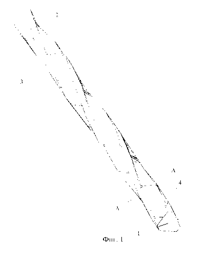
Fig. 1 schematically illustrates an outer appearance of a reinforcement wire
having
spiral profile;
Fig. 2 schematically illustrates the cross section of a reinforcement wire
having spiral
profile.
The reinforcement wire having spiral profile according to one of the
embodiments of
the invention is given in Fig. 1, 2. On the surface of the wire 1 (Fig. 1, 2)
three ruled
surfaces 2 separated from one another by the areas of a cylindrical surface 3
are
applied along a spiral line. Trapezoidal projections 4 are disposed on the
ruled surfaces
2 at an incline in a direction reversed to the direction of the spiral line of
positioning of
the ruled surfaces 2 themselves.
The reinforcement wire is manufactured, for example, as follows.
A wire 1 of circular section is manufactured beforehand. Afterwards, the wire
is
supplied through the roller cartridge revolving around it, having three
inclined rollers
that have cylindrical working surfaces with inclined grooves cut out on them.
In
addition, the ruled surfaces 2 are formed helically on the surface of the wire
1 by the

CA 03073813 2020-02-24
W02019/045595 4
PCT/RU2018/000113
action of the cylindrical rollers, and in the places where grooves are made on
the
cylindrical surface of the rollers trapezoidal projections 4 are formed
opposite to them.
On a portion of the wire surface, which is not deformed by rollers, the areas
of
cylindrical surface 3 are kept.
Simultaneously with the process of shape change the reinforcement wire being
manufactured is tensioned up to a force of 30-70% of the breaking force by any
known method, for example, between two capstans each of them being a set
composed
of a driving pulley and a non-drive pulley, or two driving pulleys. During the
interval
between passing the first and the second capstans when the reinforcement wire
is in a
straight-line tensioned state, it is heated up to the temperature of 370-430
degrees,
for example, by means of an inductance furnace, followed by forced cooling of
the
tensioned wire by a water sprayer also in a straight-line tensioned state
during the
interval between the first and the second capstans.
Upon completion of cooling the wire passes through the second capstan and is
fed to
an accumulating unit from which it is wound up in coils or is fed to a
scissors where it
is cut to specific lengths. Afterwards, the wire wound or cut to specific
lengths is
packed by the known methods.
Apart from the described method, the wire may be subjected to shape change in
a
single process run with a wire drawing operation.

Representative Drawing
A single figure which represents the drawing illustrating the invention.
Administrative Status

2024-08-01:As part of the Next Generation Patents (NGP) transition, the Canadian Patents Database (CPD) now contains a more detailed Event History, which replicates the Event Log of our new back-office solution.

Please note that "Inactive:" events refers to events no longer in use in our new back-office solution.

For a clearer understanding of the status of the application/patent presented on this page, the site Disclaimer , as well as the definitions for Patent , Event History , Maintenance Fee  and Payment History  should be consulted.

Event History

Description Date
Inactive: Office letter 2024-03-28
Application Not Reinstated by Deadline 2023-09-01
Time Limit for Reversal Expired 2023-09-01
Deemed Abandoned - Failure to Respond to a Request for Examination Notice 2023-06-12
Letter Sent 2023-03-01
Deemed Abandoned - Failure to Respond to Maintenance Fee Notice 2022-09-01
Letter Sent 2022-03-01
Common Representative Appointed 2020-11-07
Inactive: Cover page published 2020-04-20
Letter sent 2020-03-02
Request for Priority Received 2020-02-28
Inactive: IPC assigned 2020-02-28
Inactive: First IPC assigned 2020-02-28
Priority Claim Requirements Determined Compliant 2020-02-28
Application Received - PCT 2020-02-28
National Entry Requirements Determined Compliant 2020-02-24
Small Entity Declaration Determined Compliant 2020-02-24
Application Published (Open to Public Inspection) 2019-03-07

Abandonment History

Abandonment Date Reason Reinstatement Date
2023-06-12
2022-09-01

Maintenance Fee

The last payment was received on 2021-02-26

Note : If the full payment has not been received on or before the date indicated, a further fee may be required which may be one of the following

  • the reinstatement fee;
  • the late payment fee; or
  • additional fee to reverse deemed expiry.

Patent fees are adjusted on the 1st of January every year. The amounts above are the current amounts if received by December 31 of the current year.
Please refer to the CIPO Patent Fees web page to see all current fee amounts.

Fee History

Fee Type Anniversary Year Due Date Paid Date
Basic national fee - small 2020-02-24 2020-02-24
MF (application, 2nd anniv.) - small 02 2020-03-02 2020-02-24
MF (application, 3rd anniv.) - small 03 2021-03-01 2021-02-26
Owners on Record

Note: Records showing the ownership history in alphabetical order.

Current Owners on Record
OBSCHESTVO S OGRANICHENNOI OTVETSTVENNOSTYU "ARMASTIL"
Past Owners on Record
LEV MARKOVICH ZARETSKY
VENIAMIN ALEKSANDROVICH KHARITONOV
Past Owners that do not appear in the "Owners on Record" listing will appear in other documentation within the application.
Documents

To view selected files, please enter reCAPTCHA code :


To view images, click a link in the Document Description column. To download the documents, select one or more checkboxes in the first column and then click the "Download Selected in PDF format (Zip Archive)" or the "Download Selected as Single PDF" button.

List of published and non-published patent-specific documents on the CPD .

If you have any difficulty accessing content, you can call the Client Service Centre at 1-866-997-1936 or send them an e-mail at CIPO Client Service Centre.


Document
Description 
Date
(yyyy-mm-dd) 
Number of pages   Size of Image (KB) 
Abstract 2020-02-23 2 99
Representative drawing 2020-02-23 1 57
Drawings 2020-02-23 1 29
Description 2020-02-23 4 173
Claims 2020-02-23 1 19
Courtesy - Office Letter 2024-03-27 2 188
Courtesy - Letter Acknowledging PCT National Phase Entry 2020-03-01 1 586
Commissioner's Notice - Maintenance Fee for a Patent Application Not Paid 2022-04-11 1 551
Courtesy - Abandonment Letter (Maintenance Fee) 2022-10-12 1 550
Commissioner's Notice: Request for Examination Not Made 2023-04-11 1 521
Commissioner's Notice - Maintenance Fee for a Patent Application Not Paid 2023-04-11 1 548
Courtesy - Abandonment Letter (Request for Examination) 2023-07-23 1 550
International search report 2020-02-23 2 103
National entry request 2020-02-23 7 162
Declaration 2020-02-23 1 49
Maintenance fee payment 2021-02-25 1 26