Note: Descriptions are shown in the official language in which they were submitted.
CA 03073821 2020-02-24
WO 2019/045448 PCT/KR2018/009990
1
Description
Title of Invention: WASHING MACHINE AND CONTROL
METHOD THEREOF
Technical Field
[11 The present disclosure relates to a washing machine having a pulsator
in the inside of
a drum, and a method of controlling the washing machine.
Background Art
[2] A washing machine is a home appliance for washing laundry using
electric power,
and generally, the washing machine includes a tub for storing water, and a
drum for
generating mechanical energy in the inside of the tub to separate dirt from
laundry.
[31 The washing machine is classified into a top-loading type in which the
rotation shaft
of a drum stands vertically, and a front-loading type in which the rotation
shaft of a
drum extends horizontally.
[4] The top-loading type rotates a disc-shaped rotation plate disposed on
the bottom of a
tub to rotate laundry and rub it to thereby separate dirt from the laundry.
The top-
loading type consumes a large amount of water, and makes laundry tangled since
me-
chanical energy is concentrated on the bottom of the tub. Therefore, the top-
loading
type has disadvantages that it damages cloth easily and cannot wash laundry
uniformly.
[51 In contrast, the front-loading type raises laundry and drops it by
rotating the drum,
thereby separating dirt from the laundry using a falling force. The front-
loading type
could overcome the disadvantages of the top-loading type, but has a limitation
that it
has low washing performance since it washes laundry by a simple method of
dropping
laundry. Therefore, the front-loading type requires a long washing time in
order to
overcome the limitation.
[6] In order to overcome the disadvantages of the top-loading type and
front-loading
type, studies into a technical combination method of adding a pulsator to the
front-
loading type are conducted. More specifically, the combination method is to
provide a
pulsator that can rotate independently and a motor for driving the pulsator in
the inside
of the drum. Also, the combination method controls the drum and the pulsator
inde-
pendently to rotate them in different directions, thereby compensating for the
above-
described disadvantages of the top-loading type and front-loading type.
171 However, when the combination method controls the drum and the
pulsator without
considering the state of laundry contained in the inside of the drum,
dehydration ability
may be degraded. More specifically, if dehydration is performed while driving
the
pulsator when the drum contains a small amount of load or when laundry is
arranged
CA 03073821 2020-02-24
WO 2019/045448 PCT/KR2018/009990
2
properly in the inside of the drum, the laundry may be easily tangled by the
pulsator.
On the contrary, if the pulsator does not operate in the drum in which laundry
is
arranged improperly, there will be no advantage of the pulsator.
[8i In order to overcome the problem, a dehydration control method
required for the
front-loading type including the pulsator is proposed.
Disclosure of Invention
Technical Problem
[91 It is an aspect of the present disclosure to provide a washing machine
having a
pulsator in the inside of a drum, the washing machine capable of improving
ability of
dehydrating laundry and preventing noise that is generated by unstable control
of the
pulsator by controlling a rotation of the pulsator according to a state of a
load
contained in the inside of the drum, the state of the load changing by a
rotation of the
drum, and a method of controlling the washing machine.
[10] It is another aspect of the present disclosure to provide a washing
machine capable of
reducing start-up failure probability and securing a time for recharging a
dropped
Direct-Current (DC) link voltage by controlling a drum and a pulsator properly
to
thereby achieve the stability of control, and a method of controlling the
washing
machine.
[11] Additional aspects of the disclosure will be set forth in part in the
description which
follows and, in part, will be obvious from the description, or may be learned
by
practice of the disclosure.
Solution to Problem
[12] In accordance with an aspect of the present disclosure, there is
provided a washing
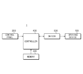
machine including: a main body having a laundry inlet in a front portion of
the main
body; a tub disposed inside the main body; a drum rotatably disposed inside
the tub; a
pulsator disposed inside the drum, and being rotatable relative to the drum; a
motor
configured to provide a driving force to the pulsator, to thereby control
rotation of the
pulsator; and a controller configured to perform a first control process of
controlling a
current flowing to the motor, in accordance with rotation of the pulsator by
movement
of laundry in the drum and that generates counter electromotive force in the
motor, to
thereby suppress the counter electromotive force, and after performing the
first control
process, perform a second control process of controlling the motor in
accordance with
rotation of the drum, to thereby control the driving force provided to the
pulsator.
[13] In the first control process, revolution per minute (rpm) of the
pulsator may be lower
than a reference rpm.
[14] In the second control process, when revolution per minute (rpm) of the
pulsator may
be higher than or equal to a reference rpm, the controller calculates a rpm
com-
CA 03073821 2020-02-24
WO 2019/045448 PCT/KR2018/009990
3
pensation ratio on the basis of the rpm of the pulsator and rpm of the drum,
and
controls the motor in accordance with the calculated compensation ratio, to
thereby
control the driving force provided to the pulsator.
[15] In the second process, the controller may determine rpm of the motor
on the basis of
the calculated compensation ratio, and control the motor on the basis of the
determined
rpm of the motor, to thereby control the driving force provided to the
pulsator.
[16] In the second control process, the controller may recalculate the
compensation ratio
on the basis of a predetermined time period, and control the motor in
accordance with
the recalculated compensation ratio.
[17] In the second control process, the controller may control the motor in
accordance
with rotation of the drum by changing revolution per minute (rpm) of the motor
in ac-
cordance with rpm of the drum.
[18] The washing machine may further include a first driving device
configured to rotate
the motor; an additional motor to provide a driving force to the drum, to
rotate the
drum; and a second driving device configured to rotate the additional motor,
to thereby
control the driving force provided to the drum.
[19] The washing machine may further include a control panel configured to
receive a
washing operation start command from a user, wherein the controller controls
the
second driving device and the first driving device sequentially in accordance
with the
washing operation start command being received by the control panel.
[20] The controller may determine the rotation of the pulsator by movement
of laundry in
the drum based on current flowing to the motor.
[21] The controller may control the drum and the pulsator such that the
drum and the
pulsator rotate in different directions.
[22] The controller may change from performing the first control process to
performing
the second control process when the pulsator is at or above a specific
revolution per
minute.
[23] The controller may change from performing the first control process to
performing
the second control process when the drum is at or above a specific revolution
per
minute.
[24] In accordance with another aspect of the present disclosure, there is
provided a
method of controlling a washing machine, the washing machine including a drum,
a
pulsator disposed inside the drum and being rotatable relative to the drum,
and a motor
configured to provide a driving force to the pulsator to thereby control
rotation of the
pulsator by the washing machine: performing a first control process of
controlling a
current flowing to the motor, according to rotation of the pulsator by
movement of
laundry in the drum and that generates counter electromotive force in the
motor, to
thereby suppress the counter electromotive force; and after performing the
first control
CA 03073821 2020-02-24
WO 2019/045448 PCT/KR2018/009990
4
process, performing a second control process of controlling the motor in
accordance
with rotation of the drum, to thereby control the driving force provided to
the pulsator.
[25] In the first control process, revolution per minute (rpm) of the
pulsator may be lower
than a reference rpm.
[26] In the second control process, when revolution per minute (rpm) of the
pulsator is
higher than or equal to reference rpm, the washing machine may calculate a rpm
com-
pensation ratio on the basis of the rpm of the pulsator and rpm of the drum,
and control
the motor in accordance with the calculated compensation ratio, to thereby
control the
driving force provided to the pulsator.
[27] In the second control process, the washing machine may determine rpm
of the motor
on the basis of the calculated compensation ratio; and control the motor on
the basis of
the determined rpm of the motor, to thereby control the driving force provided
to the
pulsator
[28] in the second control process, the washing machine may recalculate the
com-
pensation ratio on the basis of a predetermined time period, and control the
motor in
accordance with the recalculated compensation ratio.
[29] In the second control process, the washing machine may control the
motor in ac-
cordance with rotation of the drum by changing revolution per minute (rpm) of
the
motor in accordance with rpm of the drum.
[30] In the second control process, the washing machine may control the
drum and the
pulsator so that the drum and the pulsator rotate in different directions.
[31] In accordance with an aspect of the present disclosure, there is
provided a washing
machine including: a drum that is rotatable; a pulsator disposed inside the
drum, and
that is rotatable relative to the drum; a motor configured to provide a
driving force to
the pulsator, to thereby control rotation of the pulsator; and a controller
configured to,
with a rotation speed of the drum being below a predetermined rotation speed
for the
drum and a rotation speed of the pulsator being below a predetermined rotation
speed
for the pulsator, and in response to a rotation of the pulsator that generates
a counter
electromotive force in the motor, controlling a current flowing to the motor
to suppress
the counter electromotive force, and when the rotation speed of the drum
increases to
be above the predetermined rotation speed for the drum, or when the rotation
speed of
the pulsator rotates to be above the predetermined rotation speed for the
pulsator, con-
trolling the motor in accordance with rotation of the drum, to thereby control
the
driving force provided to the pulsator.
Advantageous Effects of Invention
[32] According to the washing machine of an aspect of the present
disclosure and the
control method thereof, t may be possible to prevent abnormal noise that is
caused by
CA 03073821 2020-02-24
WO 2019/045448 PCT/KR2018/009990
the instability of control of the pulsator when the drum rotates.
[33] It may be possible to prevent laundry from being damaged when the
laundry contacts
the pulsator due to a high-speed synchronized operation of the drum and the
pulsator.
[34] Also, by preventing the instability of control of the drum that is
caused by the
pulsator, it may be possible to increase the stability of control of the drum.
Brief Description of Drawings
[35] FIG. 1 is a side cross-sectional view showing a schematic
configuration of a washing
machine according to an embodiment of the present disclosure;
[36] FIG. 2 is a perspective view showing a tub and a driving device of the
washing
machine shown in FIG. 1;
[37] FIG. 3 is a side cross-sectional view showing a drum, a pulsator, and
the driving
device of the washing machine shown in FIG. 1;
[38] FIG. 4 is a perspective view showing the pulsator and a first driving
device of the
washing machine shown in FIG. 1;
[39] FIG. 5 is a perspective view showing the pulsator and a second driving
device of the
washing machine shown in FIG. 1;
[40] FIG. 6 shows the rear surfaces of the tub and the driving device shown
in FIG. 2;
[41] FIG. 7 is a control block diagram of a washing machine according to an
embodiment
of the present disclosure;
[42] FIG. 8 is a circuit diagram of a driving circuit included in a driver
of FIG. 7;
[43] FIG. 9 is a schematic view showing a state in which laundry contained
in a drum
does not rub against a pulsator;
[44] FIG. 10 is a schematic view showing a state in which laundry contained
in a drum
rubs against a pulsator to rotate the pulsator;
[45] FIG. 11 is a view for describing operations of a washing machine in
the states shown
in FIGS. 9 and 10;
[46] FIG. 12 is a view for describing another problem according to
Revolution Per Minute
(rpm) control of a pulsator in a stuck condition;
[47] FIGS. 13 and 14 are views for describing a problem that is generated
in rpm control
of a pulsator in a stuck condition;
[48] FIG. 15 is a view for describing a rpm compensation method according
to an em-
bodiment of the present disclosure;
[49] FIG. 16 is a flowchart for describing a control method of a washing
machine
according to an embodiment of the present disclosure; and
[50] FIG. 17 is a flowchart for describing a control method of a washing
machine
according to an embodiment of the present disclosure.
Best Mode for Carrying out the Invention
CA 03073821 2020-02-24
WO 2019/045448 PCT/KR2018/009990
6
[511 Configurations illustrated in the embodiments and the drawings
described in the
present specification are only the preferred embodiments of the present
disclosure, and
thus it is to be understood that various modified examples, which may replace
the em-
bodiments and the drawings described in the present specification, are
possible when
filing the present application.
[521 Also, like reference numerals or symbols denoted in the drawings of
the present
specification represent members or components that perform the substantially
same
functions.
[531 The terms used in the present specification are used to describe the
embodiments of
the present disclosure. Accordingly, it should be apparent to those skilled in
the art that
the following description of exemplary embodiments of the present invention is
provided for illustration purpose only and not for the purpose of limiting the
invention
as defined by the appended claims and their equivalents. It is to be
understood that the
singular forms "a," "an," and "the" include plural referents unless the
context clearly
dictates otherwise. It will be understood that when the terms "includes,"
"comprises,"
"including," and/or "comprising," when used in this specification, specify the
presence
of stated features, figures, steps, components, or combination thereof, but do
not
preclude the presence or addition of one or more other features, figures,
steps,
components, members, or combinations thereof.
[541 It will be understood that, although the terms first, second, etc. may
be used herein to
describe various components, these components should not be limited by these
terms.
These terms are only used to distinguish one component from another. For
example, a
first component could be termed a second component, and, similarly, a second
component could be termed a first component, without departing from the scope
of the
present disclosure.
[551 As used herein, the term "and/or" includes any and all combinations of
one or more
of associated listed items.
[561 Also, the terms "front direction" and "rear direction", when used in
this specification,
are defined based on the drawings, and the shapes and locations of the
corresponding
components are not limited by the terms.
[571 Hereinafter, the embodiments of the present disclosure will be
described in detail
with reference to the accompanying drawings.
[581 FIG. 1 is a side cross-sectional view showing a schematic
configuration of a washing
machine according to an embodiment of the present disclosure.
[591 Referring to FIG. 1, a washing machine 1 may include a main body 10
forming an
outer appearance of the washing machine 1 and accommodating various components
therein, a tub 20 disposed in the inside of the main body 10, a drum 30
accommodating
laundry and rotating, a pulsator 40 disposed in the inside of the drum 30, a
first driving
CA 03073821 2020-02-24
WO 2019/045448 PCT/KR2018/009990
7
device 110 for driving the pulsator 40, and a second driving device 130 for
driving the
drum 30.
[60] The main body 10 may be in the shape of a box. In a front portion 2 of
the main body
10, a laundry inlet 10a may be formed to allow a user to put laundry into the
inside of
the drum 30.
[61] The laundry inlet 10a of the main body 10 may be opened or closed by a
door 60.
The door 60 may be rotatably coupled to the main body 10 by a hinge member,
and
configured with a glass member and a door frame for supporting the glass
member.
[62] The glass member may be formed with a transparent tempered glass to
allow a user
to look in the inside of the main body 10. The glass member may protrude
toward the
inside of the tub 20 to prevent laundry from being gathered to the door 60.
[63] The tub 20 may store water and may be in the shape of a cylinder. The
tub 60 may be
supported by a suspension device 27. The tub 20 may include an opening 22
formed in
a side of the tub 20 in correspondence to the laundry inlet 10a of the main
body 10, and
a rear portion 23 forming the other side of the tub 20.
[64] In the rear portion 23 of the tub 20, a reinforcing rib 24 (see FIG.
2) may be formed
at regular intervals along a radial direction and a circumferential direction
in such a
way to form a grid pattern. The reinforcing rib 24 may prevent the tub 20 from
being
bent when the tub 20 is injection-molded, and also prevent a rear wall of the
tub 20
from being twisted by a weight transferred to the tub 20 upon washing or
dehydrating.
[65] The laundry inlet 10a of the front portion 2 of the main body 10 may
be connected to
the opening 22 of the tub 20 by a diaphragm 50. The diaphragm 50 may form a
passage connecting the laundry inlet 10a of the main body 10 to the opening 22
of the
tub 20, and guide laundry put through the laundry inlet 10a to the inside of
the drum
30, while preventing vibrations generated when the drum 30 rotates from being
transferred to the main body 10. Also, the diaphragm 50 may seal up between
the tub
20 and the glass member of the door 60.
[66] The drum 30 may be in the shape of a cylinder whose front portion
opens, and may
be rotatably disposed in the inside of the tub 20. That is, the drum 30 may
include an
opening 31 formed in the front portion. The central axis of the drum 30 may be
parallel
to the central axis of the tub 20.
[67] The drum 30 may rotate in the inside of the tub 20. The drum 30 may
rotate to raise
laundry and then drop it, thereby washing the laundry. In the circumference of
the
drum 30, a plurality of through holes 34 may be formed to pass washing water
stored
in the tub 20. Also, in the circumference of the drum 30, at least one
protrusion 35 may
protrude toward the inside of the drum 30. The protrusion 35 may rub against
laundry
when the laundry is washed to improve washing performance.
[68] According to an embodiment, a plurality of through holes 34 and/or a
plurality of
CA 03073821 2020-02-24
WO 2019/045448 PCT/KR2018/009990
8
protrusions 35 may be formed successively along the circumferential surface of
the
drum 30.
[69] The pulsator 40 may be disposed on a rear inner surface of the drum
30, and may
rotate on a rotation shaft. The pulsator 40 may convert a driving force
transferred from
the first driving device 110 to a rotational force, and rotate laundry.
[70] The rotation shaft of the pulsator 40 may be a rotation shaft of the
drum 30.
However, according to another embodiment, the rotation shaft of the pulsator
40 may
be different from the rotation shaft of the drum 30.
[71] The pulsator 40 may be rotatable relative to the drum 30. That is, the
pulsator 40 may
rotate in the same direction as the drum 30 or in a different direction from
the drum 30.
Details about the operation will be described in detail with reference to FIG.
7, later.
[72] A water supply 11 for supplying washing water to the inside of the tub
20 may be
disposed above the tub 20. The water supply 11 may be configured with a water
supply
pipe 12 for supplying washing water from an external water source, and a water
supply
valve 13 for opening or closing the water supply pipe 12.
[73] In a front upper portion of the main body 10, a detergent supply 14
may be disposed
to supply a detergent to the tub 20. The detergent supply 14 may be connected
to the
tub 20 through a connection pipe 15. Washing water supplied through the water
supply
pipe 12 may be supplied to the inside of the tub 20 together with a detergent
via the
detergent supply 14.
[74] The washing machine 1 may include a drain device 16 disposed on the
bottom of the
tub 20 to drain washing water. The drain device 16 may include a drain pipe 17
connected to the bottom of the tub 20 and configured to guide washing water to
the
outside of the main body 10, and a drain pump 18 for pumping washing water of
the
tub 20.
[75] FIG. 2 is a perspective view showing a tub and a driving device of the
washing
machine shown in FIG. 1. FIG. 3 is a side cross-sectional view showing a drum,
a
pulsator, and the driving device of the washing machine shown in FIG. 1. FIG.
4 is a
perspective view showing the pulsator and a first driving device of the
washing
machine shown in FIG. 1. FIG. 5 is a perspective view showing the pulsator and
a
second driving device of the washing machine shown in FIG. 1. FIG. 6 shows the
rear
surfaces of the tub and the driving device shown in FIG. 2. Hereinafter, FIGS.
2 to 6
will be described together in order to avoid overlapping descriptions.
[76] In the rear portion 23 of the tub 20, a driving device 100 including
the first driving
device 110 for supplying power to the pulsator 40 and the second driving
device 130
for supplying power to the drum 30 may be provided.
[77] The first driving device 110 may include a first driving motor 111 for
generating a
rotation force for rotating the pulsator 40, a first shaft 113 extending in a
rear direction
CA 03073821 2020-02-24
WO 2019/045448 PCT/KR2018/009990
9
from the pulsator 40 and being a rotation axis of the pulsator 40, a first
pulley 115
connected to the first shaft 113, and a first belt 117 connecting the first
driving motor
111 to the first pulley 115.
[78] The first driving motor 111 may be fixed on an outer surface of the
tub 20.
According to an embodiment, the first driving motor 111 may be installed on a
lower
end portion(25) of the tub 20.
[79] The first driving motor 111 may include a first motor shaft 111a, and
the first motor
shaft 111a may extend further in the rear direction of the main body 10 than a
second
motor shaft 131a of the second driving motor 131 which will be described
later.
According to this configuration, the washing machine 1 may be configured such
that a
first rotation path P1 formed by the first belt 117 connected with the first
motor shaft
111a does not overlap with a second rotation path P2 formed by a second belt
137
connected with the second motor shaft 131a. That is, the first belt 117 may
not
interfere with the second belt 137.
[80] The first driving motor 111 may be a motor that can rotate forward and
backward.
Accordingly, the first driving motor 111 may rotate the pulsator 40 in the
same
direction as a rotation direction of the drum 30 or in the opposite direction.
The first
driving motor 111 may be a Brushless DC (BLDC) motor.
[81] The first shaft 113 may be connected to a rear surface of the pulsator
40, and extend
along the rotation axis of the pulsator 40 from the pulsator 40. That is, the
first shaft
113 may extend in the rear direction of the pulsator 40. As shown in FIG. 3,
the first
shaft 113 may be manufactured separately from the pulsator 40 and then coupled
with
the pulsator 40. However, the first shaft 113 may be integrated into the
pulsator 40.
[82] One end of the first shaft 113 may be connected to the pulsator 40,
and the other end
of the first shaft 113 may be connected to the first pulley 115 which will be
described
later. According to this configuration, the first shaft 113 may transfer power
received
by the first pulley 115 from the first driving motor 111 to the pulsator 40 to
rotate the
pulsator 40.
[83] The first shaft 113 may be rotatably inserted into the inside of the
second shaft 133.
Accordingly, the first shaft 113 may rotate in the same direction as the
second shaft
133 or in the opposite direction of the second shaft 133.
[84] The first shaft 113 may extend longer than the second shaft 133, and
be inserted into
the second shaft 133 in such a way to protrude from both ends of the second
shaft 133.
[85] The first pulley 115 may be connected to the other end of the first
shaft 113 that is
opposite to one end of the first shaft 113 connected to the drum 30. The first
pulley 115
may include a first base portion 115a connected to the first shaft 113, a
first coupling
portion 115c coupled with the first belt 117 which will be described later and
configured to guide a rotation of the first belt 117, and a first extension
portion 115b
CA 03073821 2020-02-24
WO 2019/045448 PCT/KR2018/009990
connecting the first base portion 115a to the first coupling portion 115c.
[86] The other end of the first shaft 113 may be fixed on the first base
portion 115a, and
accordingly, when the first pulley 115 rotates, the first shaft 113 may also
rotate
together with the first pulley 115.
[87] The first coupling portion 115c may be disposed along the
circumference of the first
pulley 115, and connected to the first belt 117. As the first coupling portion
115c is
connected to the first belt 117, the first pulley 115 may receive a driving
force
generated by the first driving motor 111. The first pulley 115 may transfer
the driving
force received through the first coupling portion 115c to the first shaft 113
connected
to the first base portion 115a.
[88] At least one first extension portion 115b may extend along a radial
direction of the
first shaft 113 to connect the first base portion 115a to the first coupling
portion 115c.
However, unlike FIG. 3, the first extension portion 115b may be provided as a
single
plate extending from the first base portion 115a to the first coupling portion
115c. The
first extension portion 115b may transfer a driving force received by the
first coupling
portion 115c from the first driving motor 111 to the first base portion 115a.
[89] The first belt 117 may connect the first driving motor 111 to the
first pulley 115 to
transfer power of the first driving motor 111 to the first pulley 115. More
specifically,
the inner side of the first belt 117 may contact the first motor shaft 111a of
the first
driving motor 111 and the first coupling portion 115c of the first pulley 115
to be
coupled with the first motor shaft 111a and the first coupling portion 115c.
That is, a
rotational movement of the first belt 117 may be guided by the first motor
shaft 111a
of the first driving motor 111 and the first coupling portion 115c of the
first pulley 115.
[90] The first belt 117 may be spaced a predetermined distance d from the
second belt
137. Accordingly, the second belt 137 may not interfere with the first belt
117.
[91] Referring to FIG. 5, the second driving device 130 may include a
second driving
motor 131 for generating a rotation force for rotating the drum 30, a second
shaft 133
extending in the rear direction from the drum 30 and being a rotation axis of
the drum
30, a second pulley 135 connected to the second shaft 133, and a second belt
137
connecting the second driving motor 131 to the second pulley 135.
[92] The second driving motor 131 may be fixed on the outer surface of the
tub 20, and
provide power to the drum 30. As shown in FIG. 6, the second driving motor 131
may
be installed on another end portion of the outer circumferential surface of
the tub 20
than the lower end portion of the outer circumferential surface of the tub 20
on which
the first driving motor 111 is fixed.
[93] The second driving motor 131 may include the second motor shaft 131a,
and the
second motor shaft 131a may extend less than the first motor shaft 111a of the
first
driving motor 111 in the rear direction of the main body 10. According to this
con-
CA 03073821 2020-02-24
WO 2019/045448 PCT/KR2018/009990
11
figuration, the washing machine 1 may be configured such that the second
rotation
path P2 formed by the second belt 137 connected with the second motor shaft
131a
does not overlap with the first rotation path P1 formed by the first belt 117
connected
with the first motor shaft 111a.
[94] The second driving motor 131 may be, like the first driving motor 111,
a motor that
can rotate forward and backward. Accordingly, the second driving motor 131 may
rotate the drum 30 in a first direction or in a second direction that is
different from the
first direction. The second driving motor 131 may be a BLDC motor, like the
first
driving motor 111.
[95] The second shaft 133 may be connected to the rear surface of the drum
30, and
extend from the drum 30 along the rotation axis of the drum 30.
[96] The second shaft 133 may be a rotation axis of the pulsator 40. The
second shaft 133
may penetrate the rear portion 23 of the tub 20 to connect the drum 30 to the
second
pulley 135. The second shaft 133 may be manufactured separately from the
pulsator 40
and then coupled with the drum 30, although not limited to this. As another
example,
the second shaft 133 may be integrated into the drum 30.
[97] On the outer circumferential surface of the second shaft 133, a second
bearing 134
may be provided to rotatably support the second shaft 133. The second bearing
134
may be fixed on the tub 20.
[98] The second shaft 133 may include a cavity into which the first shaft
113 is rotatably
inserted. More specifically, the cavity of the second shaft 133 may be larger
by a pre-
determined size than a diameter of the first shaft 113 so that the first shaft
113 can be
inserted into the cavity to rotate in the cavity. According to this
configuration, the
second shaft 133 may rotate in the same direction as the first shaft 113 or in
the
opposite direction.
[99] The second shaft 133 may be shorter than the first shaft 113 so that
the first shaft 113
protrudes from both ends of the second shaft 133. According to this
configuration, a
rear plate of the drum 30 connected to one end of the second shaft 133 may be
disposed behind the pulsator 40 connected to one end of the first shaft 113,
and the
second pulley 135 connected to the other end of the second shaft 133 may be
closer to
the drum 30 than the first pulley 115 connected to the other end of the first
shaft 113.
[100] The second pulley 135, the second base portion 135a, the second
coupling portion
135c, and the second extension portion 135b for transferring a driving force
to the
drum 30 may perform the function described above in regard of the drum 30.
[101] The second belt 137 may connect the second driving motor 131 to the
second pulley
135 to transfer power of the second driving motor 131 to the second pulley
135. More
specifically, the inner side of the second belt 137 may contact the second
motor shaft
131a of the second driving motor 131 and the second coupling portion 135c of
the
CA 03073821 2020-02-24
WO 2019/045448 PCT/KR2018/009990
12
second pulley 135 to be coupled with the second motor shaft 131a and the
second
coupling portion 135c. That is, a rotational movement of the second belt 137
may be
guided by the second motor shaft 131a of the second driving motor 131 and the
second
coupling portion 135c of the second pulley 115.
[102] The second belt 137 may be spaced a predetermined distance d from the
first belt
117. Accordingly, the second belt 137 may not interfere with the first belt
117.
[103] According to an embodiment, the second belt 137 may be the same belt
as the first
belt 117. More specifically, the second belt 137 may have the same length as
the first
belt 117.
[104] In other words, the first driving motor 111, the first pulley 115,
and the first belt 117
of the first driving device 110 of the washing machine 1 may be configured
with the
same driving motor, the same pulley, and the same belt as the second driving
motor
131, the second pulley 135, and the second belt 137 of the second driving
device 130.
[105] However, the above-described components of the washing machine 1 may
be
disposed at different positions. For example, the drum 30 may be rotated by
the first
driving device 110 and the related components, and the pulsator 40 may be
rotated by
the second driving device 130 and the related components.
[106] FIG. 7 is a control block diagram of a washing machine according to
an embodiment
of the present disclosure, and FIG. 8 is a circuit diagram of a driving
circuit included in
a driver of FIG. 7.
[107] Referring to FIG. 7, the washing machine 1 may include a control
panel 200 for
receiving operation commands from a user, memory 300 for storing various in-
formation used for the control of the washing machine 1, the driving device
100 for
supplying power to the pulsator 40 and the drum 30, a driver 500 for
controlling the
driving device 100, and a controller 400 for controlling the above-described
components of the washing machine 1.
[108] More specifically, the control panel 200 may receive operation
commands for the
washing machine 1 from the user, and display operation information of the
washing
machine 1 for the user. The control panel 200 may include an input device for
receiving operation commands from the user, and a display for displaying
operation in-
formation of the washing machine 1.
[109] The input device may receive a power on/off command, a washing mode
selection
command, a water supply command, a water amount selection command, a water tem-
perature selection command, a washing operation start/stop/end command, etc.,
of the
washing machine 1.
[110] Herein, the washing operation means an operation provided as a
standard for guiding
users by a manufacturing company, etc., and may be classified into preliminary
washing, main washing, rinsing, dehydrating, etc.
CA 03073821 2020-02-24
WO 2019/045448 PCT/KR2018/009990
13
[111] The preliminary washing may be to perform first time washing for a
predetermined
time before main washing. The preliminary washing may be performed by putting
a
small amount of detergent together with water into the drum 30. The rinsing
may be
performed by putting water into the drum 30 without any detergent to remove
the
detergent included in laundry, and the rising may be performed by a
predetermined
number of times. The dehydrating may be to remove water stored in the drum 30,
and
during dehydrating, water absorbed in the laundry may be removed by mechanical
energy. The washing operation which will be described below may include all of
the
preliminary washing, the main washing, the rinsing, and the dehydrating, or
may
indicate a detailed operation.
[112] The input device may be a pressurized switch or a touch pad, and the
display may be
a Liquid Crystal Display (LCD) panel or a Light Emitting Diode (LED) panel.
[113] The input device and the display of the control panel 200 may be
separated from
each other. However, according to another embodiment, a Touch Screen Panel
(TSP)
into which an input device and a display are integrated may be provided.
However, the
input device and the display may be implemented in various ways within a range
that
can be easily designed by one of ordinary skill in the art.
[114] The memory 300 may store various data, control programs, or
applications for
driving and controlling the washing machine 1. For example, the memory 300 may
store driving programs or applications of the washing machine 1 for
controlling op-
erations of the washing machine 1 and visually providing a control screen on
the
display of the control panel 200.
[115] For example, the memory 300 may store operation order information,
operation start
time information, rotation direction information, etc. of the drum 30 and the
pulsator
40, and may also store additional information required for controlling
operations of the
drum 30 and the pulsator 40.
[116] The memory 300 according to an embodiment may store operation
information about
revolution per minute (rpm) of the second driving motor 131 for supplying a
driving
force to the drum 30 during a dehydrating operation. More specifically, the
memory
300 may store operation information for increasing rpm sequentially in the
order of
400 rpm, 800 rpm, and 1200 rpm after a dehydrating operation starts.
[117] The memory 300 may be at least one kind of storage medium among a
flash memory
type, a hard disk type, a multimedia card micro type, card type memory (for
example,
Secure Digital (SD) memory or eXtreme Digital (XD) memory), Random Access
Memory (RAM), Static Random Access Memory (SRAM), Read-Only Memory
(ROM), Electrically Erasable Programmable Read-Only Memory (EEPROM), and
Programmable Read-Only Memory (PROM), magnetic memory, a magnetic disk, and
an optical disk. However, the memory 300 is not limited to the above-mentioned
types,
CA 03073821 2020-02-24
WO 2019/045448 PCT/KR2018/009990
14
and may be implemented in various types that are known to one of ordinary
skill in the
art.
[118] The driving device 100 may transfer control signals generated by the
controller 400
as driving power to the drum 30 or the pulsator 40. The driving device 100 may
include the first driving device 110 and the second driving device 130
described above
with reference to FIGS. 1 to 6.
[119] The first driving device 110 may drive the pulsator 40 based on a
control command
generated by the controller 400, and the second driving device 130 may drive
the drum
30 based on a control command generated by the controller 400.
[120] When the pulsator 40 and the drum 30 rotate in the same direction by
the driving
device 100, the washing machine 1 may perform the same operations as a front-
loading
type washing machine.
[121] When the pulsator 40 and the drum 30 rotate in the opposite
directions, the washing
machine 1 may move laundry in a front-back direction as well as in an up-down
direction, unlike a front-loading type washing machine that drops laundry only
in the
up-down direction to wash the laundry.
[122] Also, after a washing operation starts, the washing machine 1 may
start up the drum
30 and the pulsator 40 sequentially. That is, the washing machine 1 may first
start up
the drum 30, and after a predetermined time elapses, the washing machine 1 may
start
up the pulsator 40. Alternatively, the washing machine 1 may first start up
the pulsator
40, and after a predetermined time elapses, the washing machine 1 may start up
the
drum 30.
[123] The driver 500 may transfer power to the driving device 100 based on
a control
signal generated by the controller 400 to operate the driving device 100. More
specifically, the driver 500 may adjust magnitudes of current flowing to the
driving
motors 111 and 131 included in the driving device 100 to thereby control the
rpm of
the driving motors 111 and 131.
[124] The configuration and operations of the driver 500 will be described
in detail with
reference to FIG. 8, later.
[125] Referring to FIG. 8, the driver 500 may include a rectifier circuit
511 for rectifying
Alternating-Current (AC) power received from an external power source AC, a
smoothing circuit 512 for removing ripples from the rectified power, a
plurality of
inverters (that is, a first inverter 513a and a second inverter 513b) for
generating a
driving current that is to be supplied to the driving motors 111 and 131, and
a plurality
of current sensing circuits 514a and 514b for sensing currents flowing between
the
inverters 513a and 513b and the driving motors 111 and 131.
[126] The rectifier circuit 511 may rectify AC power of 50 Hz or 60 Hz
supplied from the
external power source AC. More specifically, the rectifier circuit 511 may
control the
CA 03073821 2020-02-24
WO 2019/045448 PCT/KR2018/009990
polarity of an AC voltage that is applied in positive (+) and negative (-)
directions such
that the AC voltage is applied in the positive (+) direction, and control the
direction of
an AC current flowing in the positive (+) and negative (-) directions such
that the AC
current flows in the positive (+) direction. For example, the rectifier
circuit 511 may
include a diode bridge in which a plurality of diodes are connected in the
form of a
bridge, as shown in FIG. 8.
[127] The smoothing circuit 512 may remove ripples of a voltage output from
the rectifier
circuit 511, and output a voltage of a predetermined magnitude. That is, the
smoothing
circuit 512 may adjust a magnitude of a voltage output from the rectifier
circuit 511 to
output a constant voltage. For example, the smoothing circuit 512 may include
a
capacitor including a pair of conductor plates that are opposite to each other
and a di-
electric material disposed between the pair of conductor plates, as shown in
FIG. 8.
[128] Meanwhile, the magnitude of the constant voltage (DC link voltage)
output from the
smoothing circuit 512 may depend on the capacity of the capacitor included in
the
smoothing circuit 512, and the DC link voltage may drop by an amount of
current
consumed by operations of the driving motors 111 and 131. That is, as the
driving
motors 111 and 131 consume a larger amount of current, the smoothing circuit
512
may need a larger capacity of a capacitor.
[129] If the number of the driving motors 111 and 131 increases in order to
independently
control the drum 30 and the pulsator 40 included in the washing machine 1, the
capacity of the capacitor included in the smoothing circuit 512 may need to
increase
accordingly.
[130] When the drum 30 operates, laundry contained in the drum 30 may fall.
In this case,
the falling laundry may rotate the pulsator 40 which has stopped. The rotation
of the
pulsator 40 may generate an overcurrent in the first driving motor 111, and in
this case,
the DC link voltage may drop sharply. The sharp drop of the DC link voltage
may
cause a start-up failure or the instability of control.
[131] In order to overcome the problem, the washing machine 1 may control a
current
flowing to the first driving motor 111 to 0 A so as to prevent a counter
electro-motive
force from being generated in the first driving motor 111. Details about the
operation
will be described with reference to another drawing, later.
[132] The inverters 513a and 513b may change a DC voltage output from the
smoothing
circuit 512 to a pulsed three-phase AC having an arbitrary variable frequency
through
pulse width modulation (PWM) to control operations of the driving motors 111
and
131. For example, the inverters 513a and 513b may include a plurality of
switching
circuits Qii to Q23, and each of the plurality of switching circuits Qii to
Q23 may be im-
plemented with a free-wheeling diode and a high-voltage switch, such as a high
voltage bipolar junction transistor, a high voltage field effect transistor,
or an insulated
CA 03073821 2020-02-24
WO 2019/045448
PCT/KR2018/009990
16
gate bipolar transistor (IGBT).
[133] The washing machine 1 may control the drum 30 and the pulsator 40
independently.
Accordingly, the driver 500 may divide DC power output from the smoothing
circuit
512, and transfer the divided DC power to the first inverter 513a for rotating
the drum
30 and the second inverter 513b for rotating the pulsator 40, respectively.
[134] The current sensing circuits 514a and 514b may detect a current
flowing between the
inverters 513a and 513b and the driving motors 111 and 131. The controller 400
may
determine rpm of the driving motors 111 and 131 based on magnitudes of
currents
sensed by the current sensing circuits 514a and 514b.
[135] The washing machine 1 may determine rpm of the drum 30 and the
pulsator 40
through the current sensing circuits 514a and 514b. As described above, when
the
pulsator 40 rotates by laundry moving by a rotation of the drum 30, the
current sensing
circuit 514a may sense rpm of the pulsator 40, and the washing machine 1 may
determine a current state of the laundry contained in the drum 30 based on the
rpm of
the pulsator 40.
[136] The current sensing circuits 514a and 514b may include a current
transformer CT for
reducing a magnitude of a driving current proportionally, and an ampere meter
for
detecting the magnitude of the driving current reduced proportionally. That
is, the
current sensing circuits 514a and 514b may reduce a magnitude of a driving
current
proportionally using the current transformer, and then measure the magnitude
of the
driving current reduced proportionally to thereby detect a current.
[137] The controller 400 may control overall operations of the washing
machine 1 and
signal flow between internal components of the washing machine 1, and process
data.
When a control command is received from a user or when a predetermined
condition is
satisfied, the controller 400 may execute a control program or application
stored in the
memory 300.
[138] The controller 400 may control the drum 30 and the pulsator 40
according to a user's
command input through the control panel 200. That is, the controller 400 may
rotate
the pulsator 40 and the drum 30 sequentially based on a user's command and
prede-
termined operation information.
[139] For example, the controller 400 may first rotate the drum 30. The rpm
of the drum 30
may increase according to a predetermined time and operation information by
operation information stored in the memory 300 and a control signal of the
controller
400.
[140] When rotating the drum 30, the controller 400 may control a magnitude
of a current
flowing to the first driving motor 111 for providing a driving force to the
pulsator 40 to
0 A to suppress the generation of a counter electro-motive force.
11411 When
the rpm of the drum 30 reaches predetermined rpm, the controller 400 may
CA 03073821 2020-02-24
WO 2019/045448 PCT/KR2018/009990
17
operate the first driving motor 111. More specifically, the controller 400 may
control
the first driving motor 111 depending on the rpm of the pulsator 40 rotating
relatively
by laundry.
[142] For example, when laundry rotating by the drum 30 is a small amount
of load or
when the laundry moves quickly, the pulsator 40 may not rotate. Since a
magnitude of
current flowing to the first driving motor 111 is 0 A, the rpm of the pulsator
40 may be
0 rpm. When the rpm of the drum 30 reaches predetermined rpm, the controller
400
may increase the rpm of the first driving motor 111 from 0 rpm to the current
rpm of
the drum 30.
[143] According to another example, when laundry contained in the drum 30
drops, the
pulsator 40 may rotate. If the pulsator 40 rotates and simultaneously the drum
30
reaches the predetermined rpm, the controller 400 may increase the rpm of the
first
driving motor 111 of the pulsator 40. Unlike this example, the controller 400
may
calculate a rpm compensation ratio based on the actual rpm of the pulsator 40
and the
rpm of the drum 30, and apply the calculated rpm compensation ratio to
determine rpm
of the first driving motor 111. That is, the controller 40 may increase the
rpm of the
first driving motor 111 based on the determine rpm.
[144] Therefore, the washing machine 1 may prevent a DC link voltage from
dropping due
to a difference between the actual rpm of the pulsator 40 and the rpm of the
first
driving motor 111, and achieve the stability of control. Details about the
operation will
be described with reference to another drawing, later.
[145] Meanwhile, the controller 400 may include at least one processor,
Read Only
Memory (ROM) for storing a washing machine control program or application for
the
control of the washing machine 1, and Random Access Memory (RAM) for storing
signals or data received from the outside of the washing machine 1 or used as
storage
space for various tasks performed in the washing machine 1. The ROM and RAM of
the controller 400 may be ROM and RAM of the memory 300.
[146] The washing machine 1 may further include various other components in
addition to
the components shown in FIGS. 7 and 8, and the relative positions of the
components
may also change according to the performance and structure of the system.
[147] FIG. 9 is a schematic view showing a state in which laundry contained
in the drum
does not rub against the pulsator, FIG. 10 is a schematic view showing a state
in which
laundry contained in the drum rubs against the pulsator to rotate the
pulsator, and FIG.
11 is a view for describing operations of the washing machine in the states
shown in
FIGS. 9 and 10.
[148] Referring first to FIG. 9, the controller 400 may receive a command
from a user to
execute a washing operation. For example, the controller 400 may receive a
washing
operation start command for dehydration from a user, and generate a control
signal for
CA 03073821 2020-02-24
WO 2019/045448 PCT/KR2018/009990
18
rotating the drum 30 to control the driver 500.
[149] The driver 500 may operate the second inverter 513b based on the
control command
from the controller 400 to drive the second driving motor 131. The drum 30 may
rotate
by the second driving motor 131. Simultaneously, the controller 400 may
control a
current flowing to the first driving motor 111 for providing a driving force
to the
pulsator 40 to 0 A.
[150] When the drum 30 rotates, laundry W contained in the drum 30 may drop
repeatedly.
When the laundry W drops, the pulsator 40 may rotate. The controller 400 may
determine whether the pulsator 40 rotates, based on a current of a counter
electro-
motive force sensed by the first sensing circuit 514a.
[151] More specifically, when the detected rpm of the pulsator 40 is higher
than reference
rpm, the controller 400 may determine that the pulsator 40 rotates by the
laundry W.
Herein, the reference rpm may be set arbitrarily, and may change by a load of
the
laundry W input by the user.
[152] Meanwhile, when the laundry W is a small amount of load or when the
laundry W
scarcely rubs against the protruding pulsator 40, the pulsator 40 may not
rotate. That is,
in the state shown in FIG. 9, the drum 30 may rotate by the second driving
motor 131,
and the pulsator 40 may stop without rotating. Hereinafter, the state shown in
FIG. 9
will be referred to as a separated condition.
[153] Referring to FIG. 10, the washing machine 1 may operate the second
driving motor
131 for rotating the drum 30. When the drum 30 rotates to drop laundry W
repeatedly,
the laundry W may rotate the pulsator 40 if the laundry W is a large amount of
load or
if the laundry W gets tangled or moves randomly, as shown in FIG. 10.
Hereinafter,
the state shown in FIG. 10 will be referred to as a stuck condition.
[154] In the stuck condition, the pulsator 40 may have rpm by the laundry
W. The washing
machine 1 may generate a counter electro-motive force in the first driving
motor 111
when the pulsator 40 rotates. When the pulsator 40 rotates, a current may flow
between
the first driving motor 111 and the second inverter 513a. The first current
sensing
circuit 514a may sense the current, and transfer the sensed current to the
controller
400. In order to reduce the counter electro-motive force, the washing machine
1 may
generate a current for reducing the generated counter electro-motive force,
and apply
the current to the first driving motor 111. Thereby, the washing machine 1 may
maintain a current flowing to the first driving motor 111 at 0 A.
[155] Meanwhile, since the washing machine 1 maintains a current flowing to
the first
driving motor 111 at 0 A even in the stuck condition, the pulsator 40 may
continue to
have constant rpm.
[156] Referring to FIG. 11, the washing machine 1 may perform different
control methods
in the separated condition and the stuck condition.
CA 03073821 2020-02-24
WO 2019/045448 PCT/KR2018/009990
19
[157] When a dehydrating operation starts, the washing machine 1 may
increase the rpm of
the drum 30 sequentially, as shown in FIG. 11. That is, the rpm of the second
driving
motor 131 rotating the drum 30 may increase at regular time intervals to 0
rpm, 400
rpm, and 800 rpm in this order.
[158] In the separated condition, the pulsator 40 may not rotate or may
rotate at rpm that is
lower than reference rpm, by zero-current control.
[159] Meanwhile, when the rpm of the drum 30 continues to increase, kinetic
energy of the
laundry W contained in the drum 30 may increase. Even in the separated
condition, the
laundry W may rub against the protruding portion of the pulsator 40. That is,
the
increased kinetic energy of the laundry W may be converted into thermal energy
when
the laundry W rubs against the pulsator 40, and the thermal energy may damage
the
laundry W.
[160] In order to prevent the laundry W from being damaged, the washing
machine 1 may
operate the first driving motor 111 for driving the pulsator 40 when the drum
30 rotates
at 400 rpm or higher. More specifically, the washing machine 1 may increase
the rpm
of the first driving motor 111 to the current rpm of the drum 30, and then
control the
first driving motor 111 to the same rpm as the second driving motor 131 for
operating
the drum 30.
[161] Meanwhile, the predetermined rpm shown in FIG. 11, that is, 400 rpm
may be an
example, and may change to other values.
[162] In the stuck condition, the pulsator 40 may rotate at rpm that is
higher than the prede-
termined rpm by the laundry W. In a graph of the stuck condition shown in FIG.
11, a
dotted line shows the rpm of the pulsator 40 changed by the laundry W.
[163] When the pulsator 40 rotates, a counter electro-motive force may be
generated in the
first driving motor 111 connected to the pulsator 40. An overcurrent caused by
the
generation of the counter electro-motive force may flow to the driver 500 to
thus
damage the control circuit.
[164] General methods for suppressing the generation of a counter electro-
motive force
may include open brake control, short brake control, and field-weakening
control.
[165] More specifically, the short brake control may be a method of short-
circuiting all of
the six switches Qii to Q23 included in the first inverter 513a. When the
switches Qii to
Q23 are short-circuited, the pulsator 40 may stop rotating forcedly. However,
due to the
braking power of the first driving motor 111, a load of the second driving
motor 131
that uses the same voltage output from the smoothing circuit 512 may increase.
Therefore, the short brake control may deteriorate the dehydrating performance
of the
washing machine 1.
[166] The open brake control may open all of the six switches Qii to Q23
included in the
first inverter 513a. In this case, the first driving motor 111 may operate as
a generator
CA 03073821 2020-02-24
WO 2019/045448 PCT/KR2018/009990
by a rotation of the pulsator 40, and a current generated by a counter electro-
motive
force may be applied to the second inverter 513b and the second driving motor
131
through the diode included in the first inverter 513a. That is, a phase
difference may be
generated between a current applied by a counter electro-motive force and a
current for
the control of the second driving motor 131, thereby causing a problem in
current
sensing. As a result, the open brake control may interfere with efficient
control of the
second driving motor 131.
[167] The field-weakening control may apply the same current as that
applied to the first
driving motor 111 to the second driving motor 131 to weaken torque. However,
the
field-weakening control may have difficulties in coping with a sharp increase
of a DC
link voltage by a counter electro-motive force that is generated when the
pulsator 40
rotates at very high rpm, for example, 400 rpm.
[168] In order to resolve the above-described problems of the short brake
control, the open
brake control, and the field-weakening control, the washing machine 1 may stop
zero-
current control when the rpm of the drum 30 increases to 400 rpm or higher in
the
stuck condition, and the controller 400 may directly control the rpm of the
first driving
motor 111. Also, the controller 400 may control the rpm of the first driving
motor 111
based on the rpm of the second driving motor 131 for driving the drum 30.
[169] That is, when the rpm of the pulsator 40 increases to 400 rpm or
higher by the
laundry W, the washing machine 1 may apply a control signal to the first
driving motor
111 to control the first driving motor 111 to the same rpm as the second
driving motor
131.
[170] Meanwhile, the 400 rpm set in the stuck condition is only an example,
and arbitrary
rpm may be set.
[171] FIG. 12 is a view for describing another problem according to rpm
control of the
pulsator in the stuck condition.
[172] After a predetermined time elapses in the stuck condition, the
washing machine 1
may control the rpm of the first driving motor 111 to constant rpm, for
example, 50
rpm.
[173] In this case, when the rpm of the drum 30 increases, a difference
between the rpm of
the drum 30 and the relative rpm of the pulsator 40 may increase. When the
relative
rpm of the pulsator 40 increases, a friction force between the pulsator 40 and
the
laundry W may further increase, which may damage the laundry W.
[174] As described above with reference to FIG. 11, the washing machine 1
may control
the rpm of the first driving motor 111 for providing a driving force to the
pulsator 40 to
the same rpm as that of the second driving motor 131 in the stuck condition,
thereby
solving the above-described problem.
11751 FIGS. 13 and 14 are views for describing a problem that is generated
in rpm control
CA 03073821 2020-02-24
WO 2019/045448 PCT/KR2018/009990
21
of a pulsator in the stuck condition.
[176] As described above with reference to FIG. 11, the washing machine 1
may control
the rpm of the first driving motor 111 for driving the pulsator 40 based on
the rpm of
the second driving motor 131 for driving the drum 30, in the stuck condition.
[177] The drum 30 may rotate at 400 rpm by the second driving motor 131 for
rotating the
drum 30. Although the washing machine 1 operates the first driving motor 111
at 400
rpm in order to control the rpm of the pulsator 40 to the same rpm as that of
the drum
30, the actual rpm of the pulsator 40 may be 405 rpm in the stuck condition.
[178] Referring to FIG. 14, although the controller 400 rotates the first
driving motor 111
and the second driving motor 131 to the same control signal, for example, to
400 rpm,
the actual rpm of the pulsator 40 may be different from the rpm of the first
driving
motor 111 by mechanical errors according to the configurations and lengths of
the
pulleys 113 and 115 and the belts 117 and 137 or the kinetic energy of laundry
W
rotating by the drum 30.
[179] Accordingly, the pulsator 40 may rotate with a rotation force that is
greater than a
control signal of the controller 400, and a difference between the actual rpm
of the
pulsator 40 and the rpm of the first driving motor 111 may increase the DC
link
voltage instantaneously so as for the pulsator 40 to get out of control, as
shown in FIG.
13.
[180] In order to overcome the problem, the washing machine 1 may calculate
rpm of the
first driving motor 111 as rpm that is different from that of the second
driving motor
131, in the stuck condition.
[181] FIG. 15 is a view for describing a rpm compensation method according
to an em-
bodiment of the present disclosure.
[182] Referring to FIG. 15, the controller 400 may monitor the rpm of the
pulsator 40
caused by the laundry W based on the result of detection transferred from the
first
current sensing circuit 513a.
[183] When the rpm of the drum 30 or the rpm of the pulsator 40 is higher
than 400 rpm
which is predetermined rpm, the controller 400 may calculate a rpm
compensation
ratio based on the current rpm of the pulsator 40 and the rpm of the drum 30,
in a
section dl.
[184] The rpm compensation ratio may be calculated by Equation 1 below.
[185] [Equation 11
[186] rpm compensation ratio (a) = (rpm of the pulsator) / (rpm of the
drum)
[187] In the example of FIG. 15, the rpm compensation ratio a may be
1.0125. The
controller 400 may determine the rpm compensation ratio a in the section dl,
and
calculate rpm of the first driving motor 111 to which the rpm compensation
ratio a is
applied. The rpm of the first driving motor 111 may be calculated by Equation
(2)
CA 03073821 2020-02-24
WO 2019/045448 PCT/KR2018/009990
22
below.
[188] [Equation 21
[189] rpm of the first driving motor = (rpm of the drum) x (rpm
compensation ratio a)
[190] In the example of FIG. 15, the rpm of the first driving motor 111 may
be calculated
as 405 rpm.
[191] The controller 400 may control the first driving motor 111 based on
the calculated
rpm of the first driving motor 111, in a section d2. That is, in the stuck
condition, the
controller 400 may transfer different control signals to the first driving
motor 111 and
the second driving motor 131, respectively.
[192] Also, after calculating the rpm compensation ratio a, the controller
400 may continue
to generate a control signal related to the rpm of the first driving motor 111
at prede-
termined time intervals d3. That is, in a section in which the rpm of the drum
30
increases from 400 rpm to 800 rpm, the controller 400 may apply a rpm
compensation
ratio calculated per 1 ms (d3) to calculate rpm for controlling the first
driving motor
111, and apply the calculated rpm to the first driving motor 111.
[193] Meanwhile, 1 ms may be a predetermined time period, and may change to
another
time period.
[194] FIG. 16 is a flowchart for describing a control method of a washing
machine
according to an embodiment of the present disclosure.
[195] Referring to FIG. 16, it may be determined whether a washing
operation start
command is received, in operation 600. Then, a rotation of the drum 30 may be
controlled, in operation 610, and a current flowing to the first driving motor
111 may
be controlled to 0 A, in operation 620.
[196] The washing operation start command may be a dehydrating operation
start
command. The dehydrating operation may start by a predetermined operation
method
or by a user's command. However, the washing operation start command is not
limited
to the dehydrating operation start command, and may be another washing
operation
start command.
[197] When a dehydrating operation starts, the controller 400 may control
the second
driving motor 131 to operate the drum 30. If the second driving motor 131
operates,
the drum 30 may rotate, and the pulsator 40 may rotate by laundry W contained
in the
drum 30. When the pulsator 40 rotates, a counter electro-motive force may be
generated in the first driving motor 111. As described above, the controller
400 may
control a current flowing to the first driving motor 111 to 0 A in order to
prevent the
first driving motor 111 from being damaged by the counter electro-motive
force.
[198] That is, if a current flowing to the first driving motor 111 is
controlled to 0 A, the
pulsator 40 may rotate or not rotate according to a load of the laundry W.
[199] Thereafter, the controller 400 may determine whether the rpm of the
pulsator 40
CA 03073821 2020-02-24
WO 2019/045448 PCT/KR2018/009990
23
reaches predetermined rpm, in operation 630.
[200] When the rpm of the pulsator 40 reaches the predetermined rpm, the
controller 400
may start rpm control of the first driving motor 111, in operation 640.
[201] More specifically, in the separated condition, the controller 400 may
start rpm
control of the first driving motor 111 based on the rpm of the drum 30.
Meanwhile, in
the stuck condition, the controller 400 may start rpm control of the first
driving motor
111 in consideration of the rpm of the drum 30 and the sensed rpm of the
pulsator 40.
Details about the operation will be described with reference to FIG. 17,
later.
[202] Meanwhile, if the rpm of the drum 30 or the pulsator 40 does not
reach the prede-
termined rpm, the controller 400 may continue to control the current flowing
to the
first driving motor 111 to 0 A.
[203] FIG. 17 is a flowchart for describing a control method of the washing
machine
according to an embodiment of the present disclosure.
[204] Referring to FIG. 17, the controller 400 may sense rpm of the
pulsator 40, in
operation 700.
[205] The controller 400 may determine the rpm of the pulsator 40 based on
the result of
sensing by the first current sensing circuit 514a.
[206] Then, the controller 400 may compare the determined rpm of the
pulsator 40 to
reference rpm, in operation 710.
[207] If the rpm of the pulsator 40 is higher than or equal to the
reference rpm, the
controller 400 may determine the stuck condition in which the pulsator 40
rotates by
laundry W. In this case, the controller 400 may calculate a rpm compensation
ratio
based on the sensed rpm of the pulsator 40, in operation 720.
[208] More specifically, the rpm compensation ratio may be calculated by
the determined
rpm of the pulsator 40 and the rpm of the drum 30. As described above, the rpm
of the
drum 30 may be criteria based on which the controller 400 controls the first
driving
motor 111. Accordingly, the controller 400 may calculate the rpm compensation
ratio
based on the rpm of the drum 30 and the current rpm of the pulsator 40.
[209] The controller 400 may apply the calculated rpm compensation ratio to
determine
rpm of the first driving motor 111, in operation 730. The controller 400 may
control
the first driving motor 111 based on the determined rpm, in operation 750.
[210] Unlike this, if the rpm of the pulsator 40 is lower than the
reference rpm, the
controller 400 may determine the separated condition. Unlike the stuck
condition, the
controller 400 may decide rpm of the first driving motor 111 based on the rpm
of the
drum 30, that is, the rpm of the second driving motor 131, in operation 740.
In the
separated condition, the controller 400 may operate the first driving motor
111 based
on the determined rpm, in operation 750.
[211] Meanwhile, the controller 400 may change the rpm of the first driving
motor 111
CA 03073821 2020-02-24
WO 2019/045448 PCT/KR2018/009990
24
based on the rpm of the drum 30 and a predetermined time period, in operation
760.
[212] More specifically, in the stuck condition, the controller 400 may
determine rpm of
the first driving motor 111 in consideration of the rpm of the drum 30 and the
rpm
compensation ratio calculated in advance according to the predetermined time
period,
and apply the determined rpm to the first driving motor 111. However, in the
separated
condition, when the rpm of the drum 30 changes, the controller 400 may change
the
rpm of the first driving motor 111 accordingly.
[213] Thereby, the washing machine 1 may prevent abnormal noise due to the
instability of
control of the pulsator 40 when the drum 30 rotates, prevent laundry from
being
damaged when the laundry contacts the pulsator 40 due to a high-speed
synchronized
operation of the drum 30 and the pulsator 40, and prevent a breakdown of the
driving
device 100, which may be caused when the drum 30 operates alone, thereby
performing stable control.
[214] According to the washing machine of an aspect of the present
disclosure and the
control method thereof, it may be possible to prevent abnormal noise that is
caused by
the instability of control of the pulsator when the drum rotates.
[215] According to the washing machine of another aspect of the present
disclosure and the
control method thereof, it may be possible to prevent laundry from being
damaged
when the laundry contacts the pulsator due to a high-speed synchronized
operation of
the drum and the pulsator.
[216] Also, by preventing the instability of control of the drum that is
caused by the
pulsator, it may be possible to increase the stability of control of the drum.
[217] Although a few embodiments of the present disclosure have been shown
and
described, it would be appreciated by those skilled in the art that changes
may be made
in these embodiments without departing from the principles and spirit of the
disclosure, the scope of which is defined in the claims and their equivalents.