Note: Descriptions are shown in the official language in which they were submitted.
CA 03073940 2020-02-25
WO 2019/040820
PCT/US2018/047864
ADHESIVE ARTICLES PERMITTING DAMAGE FREE REMOVAL
Related Application
This application is related to 3M Attorney Case Nos. 79561US002 and
79561W0003, each entitled
"Adhesive Articles Permitting Damage Free Removal", filed August 25, 2017 and
August 25, 2018,
respectively, and each incorporated by reference in their entirety.
Technical Field
The present disclosure generally relates to peelable adhesive articles that
are capable of attaching or
adhering to a substrate and that can be removed from the substrate without
causing damage to the
substrate. The present disclosure also generally relates to methods of making
and using such adhesive
articles.
Background
The revolutionary Command Adhesive Strip products are a line of stretch
removable adhesive strips
that hold strongly on a variety of surfaces (including paint, wood, and tile)
and that remove cleanly - no
holes, marks, or sticky residue. These products generally have utility in
bonding to various surfaces or
substrates for numerous applications.
In general, these products include a stretch release adhesive composition
disposed on tape or other
backings. Stretch releasable adhesives are high performance pressure-sensitive
adhesives that combine
strong holding power with clean removal and no surface damage. Stretch
releasable adhesive products
are designed to firmly adhere an article, such as a hook (to hold a picture or
an article of clothing) or other
decorative or utilitarian element, to a surface (an adherend), yet remove
cleanly when pulled away from
the architectural surface at a low angle. The clean removal aspect means that
a tacky and/or unsightly
residue is not left behind on the surface after removal of the stretch release
adhesive and that no damage
to the surface occurs during the removal process. During the process of
stretch release removal, the
adhesive layer typically remains adhered to the tape backing as the backing is
stretched, but releases from
the surface (adherend).
Peelable adhesive technology was recently introduced into products for
mounting. Some exemplary
commercially available peelable mounting products (e.g., Jimmy HOOkTM
products, GeckolechTM
products, Elmer's Freestyle", products, and Hook Um", products) rely on both
suction technology and
frictional or dry adhesives to generate the mounting device's holding power.
The mounting devices
include a semi-rigid plastic backing and a rigid hook, both of which are
integrated as a one-piece article
support. The rigid hook is permanently attached to a fist major planar surface
of the semi-rigid plastic
1
CA 03073940 2020-02-25
WO 2019/040820
PCT/US2018/047864
backing. The second major planar surface of the backing can be adhered to a
wall surface. The second
major planar surface includes one or more of suction technology (e.g.,
numerous microsuction or
nanosuction elements) and/or a frictional adhesive (in which the backing is
impregnated with a rubber-
based adhesive to increase friction between the substrate and backing) or dry
adhesive (which relies on
van der Waals forces). The entire construction can, thereafter, be removed by
peeling.
Summary
Existing peelable adhesive products often do not work well on various
surfaces, including, for example,
painted surfaces and rough surfaces (e.g., drywall). Additionally, the
existing peelable products can
exhibit low shear strength and thus can hold little weight or alternatively
require a relatively thick
construction, which can cause an increase in the potential for damage when
such products are removed
from an adherend. Attempts have been made to replace existing backings with
those having lower
stiffness (modulus) to reduce the peel force upon removal. Soft, elastic
backings, for example, have been
shown to result in lower peel forces, which correlate with appreciable stretch
(strain) of the adhesive at
release. Even with advantageous modifications to the backing materials, the
present inventors recognized
that certain delicate surfaces (e.g., paper and drywall) still experienced
visible damage, particularly under
circumstances in which the ability of the backing to stretch is compromised.
As such, the inventors of the
present disclosure sought to formulate peelable mounting products and/or
adhesive articles with at least
one of higher shear strength, ability to work well on painted or rough
surfaces, and/or that are capable of
consistently holding higher weights, all without damaging the substrate to
which they are applied.
The inventors of the present disclosure recognized that the existing peel
release adhesive products could
be improved or enhanced by reducing or eliminating the contribution of the
backing to peel force
generated by the adhesive during removal. in some instances, this can be
accomplished by ensuring the
core loses structural integrity in a direction normal to a plane defined by a
major surface thereof. In other
instances, the contribution is reduced by compromising the interface between
the backing and a peelable
adhesive layer. By separating the peel force from characteristics of the
backing. the adhesive articles of
the present disclosure can capitalize on myriad backing materials and
constructions without deleteriously
impacting damage free removability. In some instances, the enhanced
construction allows the adhesive
articles to hold more weight. In some embodiments, the enhanced performance
permits the adhesive
articles to be used on new surfaces (e.g., delicate paper). In some
embodiments, the enhanced
removability increases or enhances the product performance on certain surfaces
(e.g., rough or textured
surfaces such as, for example, wallpaper, drywall, etc.).
The inventors of the present disclosure also recognized that providing a
backing that minimally
contributes to the peel release force during the removal process is a novel
and effective method to
increase performance of the adhesive article while enhancing the damage-free
features of the product.
2
CA 03073940 2020-02-25
WO 2019/040820
PCT/US2018/047864
in one aspect, the present disclosure provides an adhesive article comprising
a first peelable adhesive layer,
a second peelable adhesive layer, and a discrete core disposed between the
first and second peelable
adhesives and defining a core plane.
In another aspect, the present disclosure provides an adhesive article for
mounting an object to a surface,
the article comprising: a first adhesive layer, a core adjacent the first
adhesive layer and defining a
perimeter, the core comprising core material and including first and second
major surfaces; and a first
arranged pattern of recesses on at least the first major surface of the core,
each recess ternfinating in a
membrane comprising core material; and an adhesive interface at the bottom
wall surface, wherein the
adhesive interface comprises contact between the first adhesive layer and the
membrane.
In another aspect, the present disclosure provides a method for making an
adhesive article, the method
comprising: providing a core having first and second opposing major surfaces
and including a
consolidatable core material; laminating a peelable adhesive on at least one
of the major surfaces; and
consolidating a plurality of discrete regions of the material to form an
arranged pattern of recesses; and
creating a plurality of adhesive interfaces between the peelable adhesive and
each consolidated region of
the backing. In some embodiments, the consolidating occurs through ultrasonic
point bonding. In another
aspect, the backing is provided having a first arranged pattern of recesses,
and the consolidation creates a
second pattern of recesses.
In yet another aspect, the present disclosure provides an adhesive article for
mounting an object to a surface,
the article comprising: a first adhesive layer comprising a first peelable
adhesive composition: a core
adjacent the first adhesive layer and defining a perimeter, the core
comprising porous core material and
including first and second major surfaces; and a first arranged pattern of
recesses on at least the first major
surface of the core, each recess terminating in a membrane comprising core
material, wherein the first
peelable adhesive composition is at least partially within the pores of each
membrane.
As used herein, "porosity" means a measure of void spaces in a material. Size,
frequency, number, and/or
intercotmectivity of pores and voids contribute the porosity of a material.
As used herein, "void volume" means a percentage or fractional value for the
unfilled space within a porous
or fibrous body, such as a web or filter, which may be calculated by measuring
the weight and volume of a
web or filter, then comparing the weight to the theoretical weight of a solid
mass of the same constituent
material of that same volume.
3
CA 03073940 2020-02-25
WO 2019/040820
PCT/US2018/047864
As used herein, "Solidity" describes a dimensionless fraction (usually
reported in percent) that represents
the proportion of the total volume of a nonwoven web that is occupied by the
solid (e.g., polymeric filament)
material. Loft is 100% minus Solidity and represents the proportion of the
total volume of the web that is
unoccupied by solid material.
As used herein, "layer" means a single stratum that may be continuous or
discontinuous over a surface.
As used herein, the terms, "height", "depth", "top" and "bottom" are for
illustrative purposes only, and do
not necessarily defme the orientation or the relationship between the surface
and the intrusive feature.
Accordingly, the ternis "height" and "depth", as well as "top" and "bottom"
should be considered
interchangeable.
The terms "comprises" and variations thereof do not have a limiting meaning
where these terms appear in
the description and claims.
The words "preferred" and "preferably" refer to emboditnents of the invention
that may afford certain
benefits, under certain circumstances. However, other embodiments may also be
preferred, under the same
or other circumstances. Furthermore, the recitation of one or more preferred
embodiments does not imply
that other embodiments are not useful, and is not intended to exclude other
embodiments from the scope of
the invention.
As recited herein, all numbers should be considered modified by the term
"about".
As used herein, "a," "an," "the," "at least one," and "one or more" are used
interchangeably. Thus, for
example, a core comprising "a" pattern of recesses can be interpreted as a
core comprising "one or more"
patterns.
Also herein, the recitations of numerical ranges by endpoints include all
numbers subsumed within that
range (e.g., 1 to 5 includes 1, 1.5,2, 2.75, 3, 3.80,4, 5, etc.).
As used herein as a modifier to a property or attribute, the term -generally",
unless otherwise specifically
defined, means that the property or attribute would be readily recognizable by
a person of ordinary skill but
without requiring absolute precision or a perfect match (e.g., within +1- 20 %
for quantifiable properties).
The term "substantially", unless otherwise specifically defined, means to a
high degree of approximation
(e.g., within +1- 10% for quantifiable properties) but again without requiring
absolute precision or a perfect
match. Terms such as same, equal, uniform, constant, strictly, and the like,
are understood to be within the
4
CA 03073940 2020-02-25
WO 2019/040820
PCT/US2018/047864
usual tolerances or measuring error applicable to the particular circumstance
rather than requiring absolute
precision or a perfect match.
The above sununary of the present disclosure is not intended to describe each
disclosed embodiment or
every implementation of the present invention. The description that follows
more particularly exemplifies
illustrative embodiments. In several places throughout the application,
guidance is provided through lists
of examples, which examples can be used in various combinations. In each
instance, the recited list serves
only as a representative group and should not be interpreted as an exhaustive
list.
Brief Description of Drawings
Fig. 1 is a top plan view of one embodiment of an exemplary adhesive article
of the type generally
described herein;
Fig. 2 is a cross-sectional view of the adhesive article of Fig. 2;
Figs. 3A-3X are photographs of exemplary arranged patterns of recesses
suitable for adhesive articles of
the present disclosure;
Fig. 4 is a cross-sectional view of one embodiment of an exemplary adhesive
article of the type generally
described herein;
Fig. 5 is a cross-sectional micrograph of an adhesive article featuring an
arranged pattern of recesses
created by thermal embossing;
Fig. 6 is a cross-sectional micrograph of an adhesive article featuring an
arranged pattern of recesses
created by ultrasonic welding;
Fig. 7 is a cross-sectional view of one embodiment of another exemplary
adhesive article of the type
generally described herein;
Fig. 8 is a block diagram detailing a method of creating arranged patterns of
recesses on one or more
surfaces of a core; and
Fig. 9 is a perspective view of a hook used to conduct the Weight Hanging Test
on Exemplary adhesive
articles of the present disclosure.
Layers in certain depicted embodiments are for illustrative purposes only and
are not intended to
absolutely define the thickness, relative or otherwise, or the absolute
location of any component. While
the above-identified figures set forth several embodiments of the disclosure
other embodiments are also
contemplated, as noted in the description. In all cases, this disclosure is
presented by way of
representation and not limitation. It should be understood that numerous other
modifications and
embodiments can be devised by those skilled in the art, which fall within the
scope and spirit of the
principles of the disclosure.
5
CA 03073940 2020-02-25
WO 2019/040820
PCT/US2018/047864
Detailed Description
Various embodiments and implementations will be described in detail. These
embodiments should not be
construed as limiting the scope of the present application in any manner, and
changes and modifications
may be made without departing from the spirit and scope of the inventions.
Further, only some end uses
have been discussed herein, but end uses not specifically described herein are
included within the scope
of the present application. As such, the scope of the present application
should be determined by the
claims.
The present disclosure generally relates to adhesive articles that can be
removed from a substrate, wall, or
surface (generally, an adherend) without damage. As used herein, the terms
"without damage" and
"damage-free" or the like means the adhesive article can be separated from the
substrate without causing
visible damage to paints, coatings, resins, coverings, or the underlying
substrate and/or leaving behind
residue. Visible damage to the substrates can be in the form of, for example,
scratching, tearing,
delaminating, breaking, crumbling, straining, and the like to any layers of
the substrate. Visible damage
can also be discoloration, weakening, changes in gloss, changes in haze, or
other changes in appearance
of the substrate.
The adhesive article includes (1) one or more peelable adhesive layers
adjacent to (2) a discrete core. As
used herein, the tem "peelable" means that the adhesive article can be removed
from a substrate or
surface by peeling at angle of between about 10 and about 180 . In some
embodiments, the adhesive
article can be removed from a substrate or surface by peeling at angle of
between 30 to 120 . In some
embodiments, the adhesive article can be removed from a substrate or surface
by peeling at angle of at
least about 35 .
During peel release removal, specified regions of the core and adhesive
undergo delamination. In
particular, the articles of the present disclosure feature destructible
adhesive/core material interfaces
offset from major surfaces, preventing force from easily transferring from the
load introduced during peel
removal to an adherend. The adhesive articles are thus specifically designed
to mimic a "backingless"
construction, where the core has little to no contribution to adhesive removal
forces experienced by the
adherend. The "backingless" construction provides an adhesive article with a
peel force that does not
exceed the damage threshold on substrates including, for example. drywall,
paint, glass, etc.
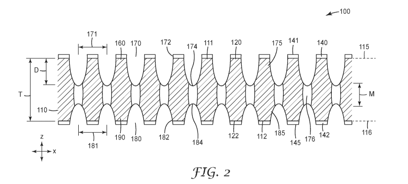
Figs. 1 and 2 depict an exemplary embodiment of an adhesive article 100 as
generally described herein.
The adhesive article 100 includes a core 110 having first and second opposed
major surfaces 111 and 112.
Fig. 1 depicts the adhesive article 100 in top plan view, with the core 110
visible through an adhesive
layer 140. In some embodiments, the adhesive 140 can be generally optically
clear such that the core is at
least partially visible. In other embodiments, the adhesive layer 140 can be
generally opaque or the core
6
CA 03073940 2020-02-25
WO 2019/040820
PCT/US2018/047864
may be otherwise not visually identifiable in top plan view. As seen in Fig.
2, the core 110 has a square
shape defmed by an upper edge, a lower edge, and side edges. The shape of the
core 110 is not
particularly limited, and can include any suitable shape or combination of
shapes. The edges cooperate to
form a core perimeter 114, which defines an identifiable boundaiy between the
core and the remainder of
the adhesive article 100 (e.g., adhesive layer 140).
The core 110 exists as a distinct structural component of adhesive article 100
and not as material
dispersed or otherwise distributed in one or both adhesive layers 140, 142.
Materials forming core 110
can include a paper, natural or synthetic polymer films, nonwovens made from
natural and/or synthetic
fibers and combinations thereof, fabric reinforced polymer films, fiber or
yarn reinforced polymer films
or nonwovens, fabrics such as woven fabric formed of threads of synthetic or
natural materials such as
cotton, nylon, rayon, glass, ceramic materials, and the like, or combinations
of any of these materials. The
core 110 may also be formed of metal, metallized polymer films, or ceramic
sheet materials in
combination with at least one of the above. In some embodiments, the core is a
multilayered film having
two or more layers; in some such embodiments the layers are laminated. For
example, the core can be
formed of a foam, a film, or a combination thereof with any suitable
thickness, composition, and
opaqueness or clarity. In other embodiments, the core may include an
arrangement of discrete particles or
an adhesive or other composition having relatively high gel content. Exemplary
materials and
constructions for the core 110 are explored in further detail below.
Combinations of two or more such
compositions and constructions are also useful in various embodiments of the
present disclosure.
In the specific embodiment of Figs. 1 & 2, the core 110 includes a single core
layer of material having a
thickness "T", though multilayer or multi-material constructions are also
contemplated and described
herein. In some embodiments, the core has a thickness "T' of between about 2
mils and about 100 mils.
In some embodiments, the core has a thickness of greater than 2 mils, greater
than 5 mils, greater than 8
mils, greater than 10 mils, greater than 12 mils, greater than 15 mils,
greater than 20 mils, greater than 22
mils, or greater than 24 mils. In some embodiments, the core has a thickness
of less than 100 mils, less
than 90 mils, less than 80 mils, less than 75 mils, less than 70 mils, less
than 65 mils, less than 60 mils,
less than 55 mils, less than 50 mils, less than 45 mils, less than 40 mils,
less than 38 mils, less than 35
mils, less than 32 inils, less than 30 mils, less than 28 mils, or less than
25 mils.
As depicted in of Fig. 2, the core 110 is generally rectangular in cross-
section, however the core may have
a variety of cross-sectional shapes. For example, the cross-sectional shape of
the core 110 may be a
polygon (e.g., square, tetrahedron, rhombus, trapezoid), which may be a
regular polygon or not., or the
cross-sectional shape of the core 110 can be curved (e.g., round or
elliptical). A first core plane 115 is
coincident with the first major surface 11.1, while a second core plane 116 is
coincident with the second
CA 03073940 2020-02-25
WO 2019/040820
PCT/US2018/047864
major surface 112. The core planes 115, 116 are depicted in parallel but may
intersect and form an
oblique angle in other embodiments.
Each of the major surfaces 111, 112 are adjacent to peelable adhesive layers
140 and 142. Peetable
adhesive layers 140 and 142 can be the same as one another or disparate from
one another. Disparate, in
this context, is used to describe substantial differences in composition or
adhesive performance.
Adhesive layers 140 and 142 can each be a single layer or can be multil*,,er.
Adhesive layers 140 and
142 can each be continuous or discontinuous (e.g., patterned) across the major
surfaces of the core 110.
Each of adhesive layers 140 and 142 include opposed major surfaces 141, 145,
respectively. An available
bond area for the article includes by the total area defmed by opposed major
surfaces 141, 145 of each
adhesive layer on the major surfaces 111, 112 of the core 110. In embodiments
featuring recesses as
detailed herein, the available bond area will not include the recesses. The
available bond areas of the
major surfaces 141, 145 are used to couple the adhesive article 100 to, for
example, a wall surface or a
hardgood. In other exemplary embodiments, an adhesive article 100 may lack an
adhesive layer on the
second major surface 112.
The adhesive layers 140 and 142, as depicted, are no more than coextensive
with the major surfaces 111,
112 of the core and are separated by the thickness "T'. The core 110 is thus
discrete from the adhesive
layers 140, 142 and includes a defined and identifiable geometry, as described
above. In other
embodiments, the adhesive layers are in contact in areas surrounding the
perimeter of the core 110. Such
constructions are described in detail in applicants co-filed provisional
application matter No.
79561US002, entitled "Adhesive Articles Permitting Damage Free Removal". The
thickness of the
adhesive layer(s) is not particularly limited, but is typically substantially
continuous across at least the
major surfaces of the core. In presently preferred implementations, the
thickness of the adhesive layer is
no greater than 95% of the core thickness "T", no greater than 90%, no greater
than 80%, no greater than
75%, no greater than 60%, no greater than 50%, no greater than 40%, no greater
than 30%, no greater
than 20%, and in some embodiments no greater than 10% of the core thickness
"T". In typical
embodiments, one or both adhesive layers 140, 142 have a thickness of between
about 1 mil and about 3
mils. The thickness of a given adhesive layer 140, 142 may be different from
the other or the same.
The core 110 includes an array of recesses 170 on the first major surface 111
and an army of recesses 180
on the second major surface 112. Recesses, for example, can include wells,
cavities, concavities, pockets.
channels, and the like. Recesses 170, 180 can have a volume with dimensions
such as diameter, radius,
depth, length, and width. A base of the recess can generally refer to a
location within the recessed feature
having points lying closest to an average elevation of a major surface, while
the surface or region of the
recess farthest from the average elevation is considered an apex or bottom
surface.
8
CA 03073940 2020-02-25
WO 2019/040820
PCT/US2018/047864
in some embodiments and as depicted in Figs. 1-2, the core 110 includes an
arranged pattern of recesses
170, 180. An "arranged pattern" is a plurality of features (e.g., recesses,
channels, etc.) arranged at
predetermined positions, arranged with some degree of regularity, or arranged
in any desired manner.
The recesses 170, 180 in core 110 are each arranged in a grid array, but other
patterns and arrangements
are possible. In some embodiments, one or both recesses 170, 180 are
distributed as a periodic array
across a core surface (e.g., a one-dimensional array or a two-dimensional
array, for example a square
array, hexagonal, or other regular army). For example, the arranged pattern of
recesses can include an
arranged row pattern, an arranged lattice pattern such as an arranged square
lattice pattern, an arranged
zigzag pattern, or an arranged radial pattern. The arranged pattern need not
be formed evenly on the entire
surface but may be formed in only a portion of a given major surface. The
pattern of recesses may vary or
remain the same over any portion of the article. For example, similar or
different patterns can be used
within the same plane. The recesses within the pattern can be of similar
geometry or can have different
geometries. Similarly, the pattern of recesses 170 on the first major surface
111 may be the same or
different than the corresponding pattern of recesses 180 on the second major
surface. In certain
implementations, the patterns on the first and second major surfaces 111, 112
may have substantially the
same pitch and recess geometty, but are offset in the transverse or
longitudinal direction, as described
below.
In one exemplary construction, the arranged pattern of features includes both
an array of discrete recesses
(e.g., wells) and a series of channels extending between and/or through
individual wells.
A Cartesian x-y-z coordinate system is included in Figs. 1 & 2 for reference
purposes. The first and
second major surfaces 111, 112 extend generally parallel to the x-y plane, and
the thickness "T" of the
core 110 corresponds to the z-axis. Each array of recesses 170, 180 includes a
transverse direction,
generally along the x-axis and a longitudinal direction, generally along the y-
axis. The arranged patterns
include a defined pitch 171, 181 between nearest-neighboring, adjacent
recesses 170, 180. The pitch
between nearest-neighboring, adjacent recesses 170, 180 in an array or pattern
may be the same in both
the transverse direction and longitudinal direction. In other embodiments, the
pitch along the transverse
direction is less than the pitch along the longitudinal direction, and vice
versa. The configuration of
recesses in any given region can be chosen so that the pitch is at least, 0.25
millimeters, at least 0.5
millimeters, in other embodiments at least 15 millimeters, in other
embodiments at least 20 millimeters, in
other embodiments at least 25 millimeters, and in yet other embodiments at
least 30 millimeters. In
certain embodiments, the pitch is no greater than 70 millimeters, in some
embodiments no greater than 60
millimeters, in some embodiments no greater than 50 millimeters, and in
certain embodiments no greater
than 45 millimeters.
9
CA 03073940 2020-02-25
WO 2019/040820
PCT/US2018/047864
The arranged pattern of recesses may result in a particular density of
recesses 170, 180 per square
centimeter. For example, the recesses can appear as discrete features in a sea
of core material, or may
encompass the majority of the core surface such that the core appears as a
mesh or scrim. in some
implementations, a major surface comprises at least 50 recesses per square
centimeter, in some
embodiments at least 100 recesses per square centimeter, in some embodiments,
at least 200, and in yet
other embodiments at least 300 microstructures per square centimeter. The core
may comprise no greater
than 2000 recesses per square centimeter, in some embodiments no greater than
1500, in some
embodiments no greater than 1000, in some embodiments no greater than 750, and
in other embodiments
no greater than 500 recesses/cm2. Without wishing to be bound by theory,
greater density of the recesses
has been shown to be correlated with higher shear performance of the adhesive
article. Under certain
circumstances, a greater density of recesses requires a higher peel force to
initiate internal delamination
where desired.
The recesses 170, 180 can take the form of any shape. Similarly, the three-
dimensional geometry of the
recesses 170, 180 is not particularly limited so long as the recess does not
extend through the thickness of
the core to the opposing major surface. The illustrated embodiment of the core
110 comprises a plurality
of circular recess bases 172, 182. Non- limiting examples of shapes that are
suitable for recess bases 172,
182 include circles, triangles, squares, rectangles, and other polygons. The
three-dimensional geometry
of the recesses 170, 180 can include circular cylindrical; elliptical
cylindrical; cuboidal (e.g., square cube
or rectangular cuboid); conical; truncated conical and the like.
Regardless of cross-sectional shape, each recess 170, 180 comprises a largest
cross-sectional dimension at
the base 172, 182 and/or the bottom surface 174, 184. The size of the largest
cross-sectional dimension is
not particularly limited, but is typically at least 0.5 millimeters. A recess
170, 180 typically includes a
depth "D" inversely related to the thickness "M" of the membrane 176. A
relatively thicker membrane
will result in shallower recess depth. It may be noted, however, that not all
recesses of the plurality of
recesses need fall within the depth range listed above.
As depicted, the recesses 170, 180 are discrete along both the transverse and
longitudinal directions. In
other embodiments, one or both recesses 170, 180 can be discrete along one
direction, such that the
apertures resemble channels in the core, or may extend diagonally (relative to
the orientation shown in
Fig. 1) across one or both the major surfaces 111, 112 of the core. Such
channels can follow any desired
path and can be continuous or discontinuous across a surface of the core in
any given direction.
Exemplary arranged patterns, some including channels are shown in Figs. 3A-3X.
The recesses 170, 180 are essentially discreet and the core 110 includes
interstitial spaces 160, 190
between adjacent recesses 170, 180, respectively. The interstitial space 160,
190 is, in the depicted
CA 03073940 2020-02-25
WO 2019/040820
PCT/1JS2018/047864
implementation, un-patterned in that it generally lacks any additional
hierarchical features. Accordingly,
the sum area of the interstitial spaces 160, 190 defines the tin-patterned
regions on the first major surface
1 1 1 and second major surface 112, respectively.
The recesses 170, 180 on each of the first major surface 111 and second major
surface 112 each have
substantially the same geometry. In other embodiments, the size or shape of
the recesses 170, 180 may
change across the transverse direction, longitudinal direction, or
combinations thereof. In yet other
embodiments, a major surface can include two or more recesses of different
geometries arranged in
repeating unit cell. The unit cell can be repeated in an arranged pattern of
unit cells. A variety of shapes
may be used to defme the unit cell, including rectangles, circles, half-
circles, ellipses, half-ellipses,
triangles, trapezoids, and other polygons (e.g., pentagons, hexagons,
octagons), etc., and combinations
thereof. In such embodiments, each unit cell boundary is directly adjacent the
boundary of a neighboring
unit cell, so that the plurality of unit cells resembles, e.g., a grid or
tessellation.
Each recess 170, 180 extends a certain depth "D" into the thickness of the
core 110 from respective
major surface 111, 112. Generally, recesses comprise a base 172, 182 adjacent
and substantially coplanar
with a major surface and a bottom surface 174, 184 separated from base 172,
182 by the depth -Ir. The
core adjacent the bottom surface 174, 184 defines a relatively thin membrane
176 of core material.
The membranes 176 separate recesses 170 on the first major surface 111 from
portions or all of recesses
180 on the second major surface 112. Any given collection of membranes can
extend along the same
plane within the core 110, such that the depth D is substantially the same for
all recesses within the
arrangement on one or both of the major surfaces 111, 112. In alternative
implementations, the location
of the membrane 176 in the z-direction within the core 110 varies along the
transverse direction, the
longitudinal direction, or both.
The membrane 176 separates the adhesive layers 140, 142 across each recess
170, 180. Each recess 170,
180 thus includes a core-adhesive interface on the bottom surface 174, 184,
one or more sidewalls 175,
185, or combinations thereof. This core-adhesive interface is hereinafter
referred to as a recess interface.
The membrane 176 typically has a thickness "M" of at least about 5% of the
thickness "T" of the core,
and in other embodiments at least about 10% of the thickness of the core. In
the same or other
embodiments, the thickness "M" is no greater than 95% of the thickness of the
core 110. In embodiments
featuring a nonwoven core, the thickness of the membrane is typically
correlated with the porosity of the
Oven nonwoven material(s). Under certain circumstances and constructions
described herein and without
wishing to be bound by theory, the structural integrity of the core can be
more easily compromised upon
peel removal with relatively thinner membranes 176 throughout the body of core
110.
11
CA 03073940 2020-02-25
WO 2019/040820
PCT/US2018/047864
in embodiments featuring a porous core material (e.g., nonwoven fabric), the
membrane 176 typically
possesses a lower porosity than the core in the non-recessed/unpatterned areas
160, 190. In some
embodiments, the void volume (or porosity) of the membrane is no greater than
50 percent, no greater
than 40 percent, no greater than 30 percent, no greater than 20 percent, and
in some other embodiments
no greater than 10 percent the porosity of the non-recessed area.
Contact between the first adhesive layer 140 and the interstitial spaces 160
defines a second core interface
120. Similarly, contact between the second adhesive layer 142 and the
interstitial spaces 190 on the
second major surface 112 defines a third core interface 122 opposing the
second core interface 120. In
.. some embodiments, the second and third interfaces 120, 122 include an area
of adhesive contact with the
core of at least about 5%; at least about 10%, at least about 25%; at least
about 30%; at least about 35%;
at least about 40%; at least about 45%; at least about 50%; at least about
55%; at least about 60%; at least
about 65%; at least about 70%; at least about 75%; or at least about 80%. in
some embodiments, the
second and third core interfaces include an area of adhesive contact between
the adhesive layer 140, 142
and the corn of between about 10% and about 100%. in some embodiments, the
second and third core
interfaces 120, 122 include an area of adhesive contact between the adhesive
layer 140, 142 and the core
of between about 40% and about 900/ The area of adhesive contact for each core
interface 120, 122 may
be the same or different. In some embodiments, including those with a hardgood
mounted to the second
peelable adhesive layer 142, the area of adhesive contact at the third core
interface 122 is greater than the
area of adhesive contact at the second core interface 120. In other
embodiments, the area of adhesive
contact at the third core interface 122 is greater than the area of adhesive
contact at the second core
interface 120. In typical embodiments, the adhesive layers 140, 142 do not
occupy all available volume
within a given aperture.
The materials making up the core 110 and adhesive layers 140, 142, as well as
the construction of the
adhesive article, can be selected so that the bond at the recess interfaces is
stronger than: 1) the bond
strength at or near the first and/or second core interfaces 120, 122; 2) the
structural integrity (e.g.,
cohesive strength) of the core 110 in a direction substantially perpendicular
to the core plane 115 or 3)
combination thereof.
The relationship between the recess interface and the core interfaces can be
expressed as a Peel Ratio,
which is defmed as the peel strength (oz/in2) at the recess interfaces
compared to the peel strength at the
core interface(s). In some embodiments, the Peel Ratio can be at least 1.15:1;
in some embodiments at
least 1.25:1; in some embodiments at least 1.5:1; in some embodiments at least
2:1; in some embodiments
at least 3:1; in some embodiments at least 5:1; in some embodiments at least
10:1; in some embodiments
at least 15:1; in some embodiments at least 20:1.
12
CA 03073940 2020-02-25
WO 2019/040820
PCT/US2018/047864
The recesses 170, 180 can be created in a core material before, during, or
after an adhesive layer has been
applied to a major surface. The recesses 170 can be created by a combination
of force and thermal/fusion
energy, such as ultrasonic welding (or bonding), thermal contact welding,
and/or point welding to reduce
the thickness (i.e., consolidate) of core material. In implementations
featuring a nonwoven or other
porous core material, the creation of recesses 170, 180 can condense the core
material by reducing
porosity and/or causing core material to flow into regions of the core
adjacent the bonding site. In certain
implementations of the embodiment in Figs. 1-3, the recesses are created by
ultrasonic point bonding of
the adhesive layer and the core according to an arranged pattern. Point
bonding may also occur by, for
example, by passing the core and the adhesive layer(s) through a heated
patterned embossing roll nip.
The point bonding creates an intermittent bond between the adhesive and core,
condensing a portion of
both the peelable adhesive and core material into the depths of individual
recesses. In other
embodiments, the desired pattern (including one or multiple patterns) may be
created in the core prior to
application of the adhesive layer. In yet other embodiments, multiple patterns
may be created in the core,
one or more prior to application of the adhesive layer and one or more after
application of the adhesive
layer.
Ultrasonic welding (or bonding) generally refers to a process performed, for
example, by passing the
requisite layers of material between a sonic horn and a patterned roll (e.g.,
anvil roll). Such bonding
methods are well-known in the art. For instance, ultrasonic welding through
the use of a stationary horn
and a rotating patterned anvil roll is described in U. S. Patent 3,844,869
(Rust Jr.); and U. S. Patent
4,259,399, "Ultrasonic Nonwoven Bonding," (Hill). Moreover, ultrasonic welding
through the use of a
rotary horn with a rotating patterned anvil roll is described in U. S. Patent
5,096,532 (Neuwirth, et al.); U.
S. Patent 5, 110,403 (Ehlert); and U. S. Patent 5,817,199, (Brennecke, et
al.). Of course, any other
ultrasonic welding technique may also be used in the present invention.
In embodiments featuring a non-woven core, the intermittent bonding of the
adhesive to the nonwoven
fabric or web (e.g., using at least one of heat, pressure, or ultrasonics as
described above) to create
recesses can collapse (i.e., condense or consolidate) porous structure at or
in the bond sites, insulting in
the creation of membranes 176. The bond sites may be see- through regions of
lower porosity that
contrast with the surrounding region. The term "see-through" refers to either
transparent (that is, allowing
passage of light and permitting a clear view of objects beyond) or translucent
(that is, allowing passage of
light and not permitting a clear view of objects beyond). The see-through
region may be colored or
colorless. It should be understood that a "see-through" region is large enough
to be seen by the naked eye.
In certain embodiments, the material for the core 110 is selected so that it
forms a relative weak bond with
either adhesive layer.
13
CA 03073940 2020-02-25
WO 2019/040820
PCT/US2018/047864
In other embodiments, the material or construction of the core is selected so
that it delaminates, fails
cohesively, or otherwise separates upon application of force generated on the
adhesive article during
removal.
Even in embodiments featuring a destructible core, the core 110 can still
provide sufficient strength along
the general plane of its separation so that, depending on the specific
application, the structural integrity of
the core will not fail based on the use of the adhesive article 100 for
'mounting an object on a mounting
surface. The core 110 can advantageously provide an internal static shear
strength in a direction parallel
to the core planes 115, 116 sufficient for supporting an object and providing
a level of resiliency to the
article 100.
Another exemplary embodiment of an adhesive article 200 is depicted in Fig. 4.
Except as otherwise
noted, all other considerations regarding the adhesive article 100 apply
equally to adhesive article 200.
Like the adhesive article of Figs. 1 and 2, the adhesive article 200 includes
a core 210, a first peelable
adhesive layer 240 on a first major surface 211 of the core 210, and a second
peelable adhesive layer 242
on a second major surface 212 of the core 210. The core 210 is comprised of
one or more porous
materials and typically includes a nonwoven web.
The core 210 includes an arranged pattern of recesses 270, 280 on the first
major surfaces 211 and second
major surface 212, respectively, extending to a depth "D" within the core
material. The recesses 270, 280
are typically arranged in the same pattern, with each opposing recess
possessing substantially the same
geometry. In certain implementations, the recesses 280 on the second major
surfaces may be smaller at
the base 281 than those on the first major surface 270.
The core 210 adjacent the bottom surface 274, 284 defines a relatively thin
membrane 276 of core
material. The membranes 276 separate recesses 270 on the first major surface
211 from portions or all of
recesses 280 on the second major surface 212. Any given collection of
membranes can extend along the
same plane within the core 210, such that the depth D is substantially the
same for all recesses within the
arrangement on one or both of the major surfaces 211, 212. In alternative
implementations, the location
of the membrane 276 in the z-direction within the core 210 varies along the
transverse direction, the
longitudinal direction, or both.
Unlike membrane 176, the membrane 276 is at least partially infused with
adhesive. In certain presently
preferred embodiments, an adhesive article includes a peelable adhesive
composition at least partially
within the pores of a porous core. For such embodiments, at least 40 volume %,
at least 50 volume A., at
least 60 volume /0, at least 70 volume %, at least 80 volume %, preferably at
least 90 volume %, and
more preferably 100 volume % of the void volume is filled with the peelable
adhesive composition. The
14
CA 03073940 2020-02-25
WO 2019/040820
PCT/US2018/047864
amount of adhesive within the pores will depend on, among other things. the
modulus of the adhesive, the
method used to create the recesses, the thickness of the core, and the
porosity of the core material.
Depending on the degree of infiltration of the 'membrane voids, at least some
of the bottom walls 274, 284
and sidewalls 273, 283 of the recesses 270, 280 may include a thin adhesive
layer (not shown).
The embodiment of Fig. 4 may be created by methods described above. In
presently preferred
implementations, the core 210 is pattern embossed, according to procedures
well known in the art, such as
those described in U.S. Patent Nos. 2,464,301 (Francis Jr.), 3,507,943 (Such
etal.), 3,737,368 (Such et
al.), and 6,383,958 (Swanson et al) and set forth in more detail below. In
general, the core and adhesive
layer(s) are passed through a metal roll that is patterned (e.g., engraved)
with raised and depressed areas,
and a solid back-up roll, generally formed of metal or rubber. However, the
core can also be fed between
two patterned rolls displaying corresponding or alternating engraved areas. In
either case, it is typical to
supply heat to one or more of the rolls so that the core is thermally bonded
along the points of pattern
contact.
While not wishing to be bound by any particular theory, it is believed that
the recesses in the embossed
pattern are formed by localized melting of the core in the pattern of the
raised areas on the patterned
embossing roll. The core is not destroyed by the process but, instead,
maintains its integrity. Moreover,
the heat from the one or more rolls causes the adhesive to flow into at least
some of the voids in the core
prior to and/or contemporaneous with the creation the recesses through contact
pressure, as can be seen in
Fig. 5. Typically, the majority of the adhesive will remain within membrane
voids, though some volume
may flow into the surrounding core as well. As used herein, "embossed pattern"
refers to a predetermined
configuration of recesses on a surface of the core. An embossed pattern is
distinguishable from a
"perforated" pattern, which refers to a predetermined configuration of
punctures that pass through the
entire thickness of the core. For instance, an array of recesses created
through heated pattern embossing
an adhesive laminated nonwoven will typically include a greater amount of
adhesive within the voids in
comparison to the same pattern created through ultrasonic welding.
Under certain conditions, the use of ultrasonic welding can result in little
to no adhesive infused in the
membrane, with core material itself instead infused into the adjacent voids. A
recess and membrane
exemplifying this result are shown in Fig. 6 and were created under conditions
similar to Example 18
below.
When an array of recesses is created by pattern embossing, the degree of
reduction in void volume due to
consolidation or densification in a given membrane may be reduced relative to
the consolidation resulting
from ultrasonic welding. in some embodiments featuring an embossed pattern(s),
the void volume (or
CA 03073940 2020-02-25
WO 2019/040820
PCT/US2018/047864
porosity) of the membrane is no greater than 90 percent, no greater than 70
percent, no greater than 60
percent, no greater than 50 percent, and in some other embodiments no greater
than 40 percent the
porosity of the non-recessed area of the core.
Fig. 7 depicts another exemplary embodiment of an adhesive article of the type
generally described herein
including a hardgood 490, a core 410 and first and second peelable adhesive
layers 440, 442. The core
410 can be any of the materials and constructions described herein and
includes an arranged army of
recesses 470, 480 extending to a depth "D" within the core material. A second
major surface 494 of
hanigood 490 is affixed to the second adhesive layer 442, creating a plurality
of hardgood interfaces 498
in a plane generally parallel if not coplanar with core plane 416. Contact
between the adhesive layer 440
and first major surface 411 defmes a core interface 420 disposed in a plane
above the hardgood interfaces
498. The first major surface 441 of the adhesive layer 440 can be used to fix
the article 400 to the desired
adherend (e.g., wall surface, cabinet surface, etc.). A second core interface
422 is formed by contact
between the second major surface 412 of the core 410 and the second adhesive
layer 442, and exists in a
plane generally parallel to the core plane 416.
In other embodiments (not depicted) the core may be fixed to the hardgood
during the selective
consolidation of core material to create recesses. Such embodiments may lack a
second adhesive layer
between the core and the hardgood.
In certain embodiments, the second adhesive layer 442 may be applied at a
greater coating weight than
the first adhesive layer 440. The disparity in coating weight and/or layer
thickness can ensure the core
stays with the hanigood when the adhesive article 400 is removed from an
adherend.
The adhesive articles of the present disclosure include available bond areas
defined by the total area of the
unpattemed region of the core (i.e., the area within each recess (aperture or
channel) is excluded from the
bond area calculation, since the adhesive within the depths of the recesses
will not typically contribute as
much to the bond of the article to the desired adherend). In some embodiments,
the available bond area
of the article is at least about 5%; at least about 10%, at least about 25%;
at least about 30%; at least about
35%; at least about 40%; at least about 45%; at least about 50%; at least
about 55%; at least about 60%; at
least about 65%; at least about 70%; at least about 75%; or at least about 80%
of an expected surface area
of a core material including like dimensions and lacking recesses. In some
embodiments, the articles
include an available bond area of between about 10% and about 90%. In yet
other embodiments, the
articles include an available bond area of between about 15% and about 70% of
an expected surface area
of a core material including like dimensions and lacking recesses.
Constituent elements of the adhesive articles described herein are explored in
more detail below.
16
CA 03073940 2020-02-25
WO 2019/040820
PCT/US2018/047864
Core
The core is part of the adhesive construction and interferes with the
interfacial bonding of portions of
otherwise adjacent adhesive layers. The core can be a single layer or a
multilayer construction. More
than one core layer can be present in the core. Multiple core layers can be
separated by layers of film,
which may further contain one or more layers. In some embodiments, the core
includes at least one of
plastic, metal, paper, nonwoven material, textile, woven material, foam,
adhesive, gel, and/or a filament
reinforced material. In some embodiments, the core is at least one of a single
layer of material or a
muhilayer film. In other embodiments, the core can be an arrangement of
particles disposed between
adjacent adhesive layers.
In some embodiments, two or more sub-layers can be co-extruded so as to form
the core. In some
embodiments, the core is flexible. Some embodiments include dyes or pigments
in the core layer. Some
embodiments include at least one tackifier in at least one layer of the core.
Some embodiments include a
plasticizing oil in one or more layers of the core.
The core can be any desired shape including, for example, square, rectangle,
triangular, polygon, circular,
qu$drilateral, trapezoidal, cylindrical, half-circular, star-shaped, half-moon
shaped, tetrahedral, etc.
The core can be made of any desired material or materials. Representative
examples of materials suitable
for the core can include, for example, polyolefins, such as polyethylene,
including high density
polyethylene, low density polyethylene, linear low density polyethylene, and
linear ultralow density
polyethylene, polypropylene, and polybutylenes; vinyl copolymers, such as
polyvinyl chlorides, both
plasticized and unplasticized, and polyvinyl acetates; olefmic copolymers,
such as ethylene/methacrylate
copolymers, ethylene/vinyl acetate copolymers, acrylonitrile-butadienestyrene
copolymers, and
ethylene/propylene copolymers; acrylic polymers and copolymers; polyurethanes;
and combinations of
the foregoing. Mixtures or blends of any plastic or plastic and elastomeric
materials such as
polypropylene/polyethylene, polyurethane/polyolefm,
polyurethane/polycaroonate,
polyurethane/polyester, can also be used.
In some embodiments, the core is or includes a composite foam that includes a
flexible polymeric foam
layer, a first film laminated to a first major surface of the foam layer, and
a second film laminated to a
second, opposite major surface of the foam layer. Adhesive(s) can be attached
to the films to form a
structure of adhesive-film-foam-film-adhesive. The flexible polymeric foam
layer can be chosen to
optimize conformability and resiliency properties which are helpful when an
adhesive article is to be
adhered to surfaces having surface irregularities, such as a typical wall
surface. An exemplary flexible
polymeric foam layer is commercially available under the trade designation
"Command" from 3M
17
CA 03073940 2020-02-25
WO 2019/040820
PCT/US2018/047864
Company of St. Paul, Mimi. In some embodiments, the flexible polymeric foam
layer of the core can
include polyolefm foams which are available under the trade designations -
Volextra" and "Volara" from
Voltek, Division of Sekisui America Corporation, Lawrence, Mass. In some
embodiments, the core is or
includes a metal or is metal-like. In some embodiments, the core is or
includes wood or is wood-like.
The core can be or include any of the materials or backings described in any
of the following patent
applications, all of which are incorporated in their entirety herein, PCT
Application No.
US2018/024347 and WO Publication Nos. 2015/195344, 2017/136432, and
2018/039584.
In various embodiments, the backing can be fabricated or produced from
microstructurecl tape materials
described in, e.g., U.S. Pat. No. 8,530,021 to Bartusiak et at.
The core can be substantially non-stretchable or can be elastic. In some
embodiments, the core material
has a storage modulus of between about 15 x 103Pa and about 2.5 x 10⁶ Pa at 25
degrees Celsius. in
other embodiments including those with glass materials or other ceramics, the
core material can have a
storage modulus of up 1 x 10¹⁰ Pa. In some embodiments, the core material has
a tan 8 (where tan 8 is
the loss modulus divided by the storage modulus) of between about 0.4 and
about 1.2 at 25 degrees
Celsius. In some embodiments, the core has a glass transition temperature of
between about -125 and
about 40 degrees Celsius. In other embodiments, the core material has a stress
relaxation between 10%
and 100% after 10 seconds.
In some embodiments, the core exhibits an elastic recovery of 1-99% at 100/0
strain. In some
embodiments, the core exhibits an elastic recovery of 1-99% at 20% strain. In
some embodiment of the
disclosure, the core material has an elongation at break of greater than 50%
in at least one direction. In
some embodiment of the disclosure, the core material has an elongation at
break of between about 50%
and about 1200% in at least one direction.
In some embodiments, the core has a Young's modulus of between about 100 psi
and about 100,000 psi.
In other embodiments featuring glass materials or ceramics, the core may have
a Young's modulus of up
to 10,000,000 psi. In some embodiments, the core exhibits an elastic recovery
of 1-100% at 10% strain as
measured by ASTM D5459-95. In some embodiments, the core exhibits an elastic
recovery of 1-100% at
20% strain.
In some embodiments, the core has a modulus of elasticity and/or a modulus of
secant of between about
100 psi and about 15,000 psi as determined by at least one of ASTM D638-14 and
ASTM D412-06a. In
some embodiments, the core has a modulus ranging between 100 psi and 15000
psi. In some
embodiments the modulus is greater than 100 psi, greater than 500 psi, greater
than 1000 psi. In some
18
CA 03073940 2020-02-25
WO 2019/040820
PCT/US2018/047864
embodiments the core modulus is less than 15000 psi, less than 10000 psi, less
than 8,000 psi, less than
5,000 psi, less than 3,500 psi, less than 2000 psi, and less than 1500 psi.
In some embodiments, the core has a thickness of between about 0.1 mils and
about 100 mils. In some
embodiments, the core has a thickness of greater than I mil, greater than 5
mils, greater than 8 mils,
greater than 10 mils, greater than 12 mils, greater than 15 mils, greater than
20 mils, greater than 22 mils,
or greater than 24 mils. In some einbodiments, the core has a thickness of
less than 100 mils, less than 90
mils, less than 80 inils, less than 75 mils, less than 70 mils, less than 65
mils, less than 60 mils, less than
55 mils, less than 50 mils, less than 45 mils, less than 40 mils, less than 38
tnils, less than 35 mils, less
than 32 mils, less than 30 mils, less than 28 mils, or less than 25
Nonwovens
In some presently preferred embodiments, the core includes a nonwoven
substrate. The nonwoven
substrate can be a nonwoven fabric or web manufactured by any of the commonly
known processes for
producing nonwoven fabric or webs. As used herein, the term "nonwoven" refers
to a fabric that has a
structure of individual fibers or filaments which are randomly and/or
unidirectionally interlaid in a mat-
like fashion, but not in an identifiable manner as in a knitted fabric.
Nonwoven fabrics or webs can be
formed from various processes such as meltblowing processes, spunbonding
processes, sptmlacing
processes, and bonded carded web processes, air laying processes, and wet
laying processes. In some
embodiments, the core comprises multiple layers of nonwoven materials with,
for example, at least one
layer of a meltblown nonwoven and at least one layer of a spunbonded nonwoven,
or any other suitable
combination of nonwoven materials. For example, the core may be a spunbond-
meltbond-spunbond,
spunbond-spunbond, or spunbond- spunbond-spunbond rnultilayer material. Or,
the core may be a
composite web comprising a nonwoven layer and a film layer.
"Meltblowing", as used herein, means a method for forming a nonwoven fibrous
web by extruding a
molten fiber-forming material through a plurality of orifices in a die to form
fibers while contacting the
fibers with air or other attenuating fluid to attenuate the fibers into
fibers, and thereafter collecting the
attenuated fibers. An exemplary meltblowing process is taught in, for example,
U. S. Patent No.
6,607,624 (Berrigan et al.). "Mehblown fibers" means fibers prepared by a
meltblowing or meltblown
process. "Spun-bonding" and "spun bond process" mean a method for forming a
nonwoven fibrous web
by extruding molten fiber-forming material as continuous or semi-continuous
fibers from a plurality of
fine capillaries of a spinneret, and thereafter collecting the attenuated
fibers. An exemplary spun-bonding
process is disclosed in, for example, U. S. Patent No. 3,802,817 to Matsuki et
al. "Spun bond fibers" and
"spun-bonded fibers" mean fibers made using spun- bonding or a spun bond
process. Such fibers are
generally continuous fibers and are entangled or point bonded sufficiently to
form a cohesive nonwoven
fibrous web such that it is usually not possible to remove one complete spun
bond fiber from a mass of
19
CA 03073940 2020-02-25
WO 2019/040820
PCT/US2018/047864
such fibers. The fibers may also have shapes such as those described, for
example, in U. S. Patent No.
5,277,976 to Hogle et al, which describes fibers with unconventional shapes.
"Canting" and "carding
process" mean a method of forming a nonwoven fibrous web webs by processing
staple fibers through a
combing or carding unit, which separates or breaks apart and aligns the staple
fibers in the machine
direction to form a generally machine direction oriented fibrous nonwoven web.
Exemplary carding
processes and carding machines are taught in, for example, U. S. Patent Nos.
5,114,787 to Chaplin et al.
and 5,643,397. "Bonded carded web" refers to nonwoven fibrous web formed by a
carding process
wherein at least a portion of the fibers are bonded together by methods that
include for example, thermal
point bonding, autogenous bonding, hot air bonding, ultrasonic bonding, needle
punching, calendering,
application of a spray adhesive, and the like. Further details regarding the
production and characteristics
of nonwoven webs and laminates including nonwoven webs may be found, for
example, in US Patent No.
9,469,091 (Henke et al.), which is incorporated by reference in its entirety
herein. "Air-laying" refers to a
process in which bundles of small fibers having typical lengths ranging from
about 3 to about 52
millimeters (mm) are separated and entrained in an air supply and then
deposited onto a forming screen,
usually with the assistance of a vacuum supply. The randomly oriented fibers
may then be bonded to one
another using, for example, thermal point bonding, autogenous bonding, hot air
bonding, needle
punching, calendering, a spray adhesive, and the like. An exemplary air-laying
process is taught in, for
example, U.S. Patent No. 4,640,810 to Laursen et al. "Wet-laying" refers to a
is a process in which
bundles of small fibers having typical lengths ranging from about 3 to about
52 millimeters (mm) are
separated and entrained in a liquid supply and then deposited onto a forming
screen, usually with the
assistance of a vacuum supply. Water is typically the preferred liquid. The
randomly deposited fibers
may by further entangled (e.g., hydro-entangled), or may be bonded to one
another using, for example,
thermal point bonding, autogeneous bonding, hot air bonding, ultrasonic
bonding, needle punching,
calendering, application of a spray adhesive, and the like. An exemplary wet-
laying and bonding process
is taught in, for example, U.S. Patent No. 5,167,765 to Nielsen et al.
Exemplary bonding processes are
also disclosed in, for example, U.S. Patent 9,139,940 to Berrigan et al.
Fibrous materials that provide useful nonwoven cores may be made of natural
fibers (e.g., wood or cotton
fibers), synthetic fibers (e.g., thermoplastic fibers), or a combination of
natural and synthetic fibers.
Exemplary materials for forming thermoplastic fibers include polyolefms (e.g.,
polyethylene,
polypropylene, polybutylene, ethylene copolymers, propylene copolymers,
butylene copolymers, and
copolymers and blends of these polymers), polyesters, and polyamides. The
nonwoven substrate may be
formed from fibers or filaments made of any suitable thermoplastic polymeric
material. Suitable
polymeric materials include, but are not limited to, polyolefins,
poly(isoprenes), poly(butadienes),
fluorinated polymers, chlorinated polymers, polyamides, polyimides,
polyethers, poly(ether sulfones),
poly(sulfones), poly(vinyl acetates), copolymers of vinyl acetate, such as
poly(ethylene)-co-poly(vinyl
alcohol), poly(phosphannes), poly(vinyl esters), poly(vinyl ethers),
poly(vinyl alcohols), and
CA 03073940 2020-02-25
WO 2019/040820
PCT/1JS2018/047864
poly(caroonates). Suitable polyolefins include, but are not limited to,
poly(ethylene), poly(propylene),
poly(14-mtene), copolymers of ethylene and propylene, alpha olefm copolymers
(such as copolymers of
ethylene or propylene with 1-butene, 1-hexene, I-octene, and 1-decene),
poly(ethylene-co-14Dutene) and
poly(ethylene-co-l-butene-co-1 -hexene). Suitable fluorinated polymers
include, but are not limited to,
poly(vinyl fluoride), poly(vinylidene fluoride), copolymers of vinylidene
fluoride (such as
poly(vinylidene fluoride-co-hexafluoropropylene), and copolymers of
chlorotrifluoroethylene (such as
poly(ethylene-co-chlorotrifluor)ethylene). Suitable polyamides include, but
are not limited to:
poly(itninoadipoyliminohexamethylene), poly(iminoadipoyliminodecamethylene),
and polycaprolactam.
Suitable polyiraides include poly(pyromellitimide). Suitable poly(ether
sulfones) include, but are not
limited to, poly(diphetwlether sulfone) and poly(diphenylsulfone-co-
diplienylene oxide sulfone). Suitable
copolymers of vinyl acetate include, but are not limited to, poly(ethylene-co-
vinyl acetate) and such
copolymers in which at least some of the acetate groups have been hydrolyzed
to afford various
poly(vinyl alcohols) including, poly(ethylene-co-vinyl alcohol).
.. The fibers may also be multi- component fibers, for example, having a core
of one thermoplastic material
and a sheath of another thermoplastic material. The sheath may melt at a lower
temperature than the core,
providing partial, random bonding between the fibers when the mat of fibers is
exposed to a sheath melts.
A combination of mono-component fibers having different melting points may
also be useful for this
puipose. In some embodiments, the nonwoven fabric or web useful in the core
according to the present
.. disclosure is at least partially elastic. Examples of polymers for making
elastic fibers include
thermoplastic elastomers such as ABA block copolymers, polyurethane
elastomers, polyolefin elastomers
(e.g., metallocene poly olefin elastomers), olefin block copolymers, polyamide
elastomers, ethylene vinyl
acetate elastomers, and polyester elastomers. An ABA block copolymer elastomer
generally is one where
the A blocks am polystyrenic, and the B blocks are prepared from conjugated
dienes (e.g., lower allcylene
.. dienes). The A block is generally formed predominantly of substituted
(e.g., alkylated) or unsubstituted
styrenic moieties (e.g., polystyrene, poly(alphamethylstyrene), or poly(t-
butylstyrene)), having an average
molecular weight from about 4,000 to 50,000 grams per mole. The B block(s) is
generally formed
predominantly of conjugated dienes (e.g., isoprene, 1,3 -butadiene, or
ethylene -butylene monomers),
which may be substituted or unsubstituted, and has an average molecular weight
from about 5,000 to
500,000 grams per mole. The A and B blocks may be configured, for example, in
linear, radial, or mar
configurations. An ABA block copolymer may contain multiple A and/or B blocks,
which blocks may be
made from the same or different monomers. A typical block copolymer is a
linear ABA block copolymer,
where the A blocks may be the same or different, or a block copolymer having
more than three blocks,
predominantly terminating with A blocks. Multi -block copolymers may contain,
for example, a certain
proportion of AB diblock copolymer, which tends to form a more tacky
elastomeric film segment. Other
elastic polymers can be blended with block copolymer elastomers, and various
elastic polymers may be
blended to have varying degrees of elastic properties. Many types of
thermoplastic elastomers are
21
CA 03073940 2020-02-25
WO 2019/040820
PCT/US2018/047864
commercially available, including those from BASF, Florham Park, N.J., under
the trade designation
"STYROFLEX", from Kraton Polymers, Houston, Tex., under the trade designation
"KRATON", from
Dow Chemical, Midland, Mich., under the trade designation "PELLETHANE",
"INFUSE", VERSIFY",
or "NORDEL", from DSM, Heerlen, Netherlands, under the trade designation
"ARNITEL", from E. I.
duPont de Nemours and Company, Wilmington, Del., under the trade designation
"HYTREL", from
ExxonMobil, Irving, Tex. under the trade designation "VISTAMAXX", and more.
For example, the fibrous nonwoven web can be made by carded, air laid, wet
laid, sprmlaced,
spunbonding, electrospinning or melt-blowing techniques, such as melt-spun or
melt-blown, or
combinations thereof. Any of the non-woven webs may be made from a single type
of fiber or two or
more fibers that differ in the type of thermoplastic polymer, shape, and/or
thickness; the single fiber type
or at least one of the multiple fiber types may each be a multicomponent fiber
as described above.
Staple fibers may also be present in the web. The presence of staple fibers
generally provides a loftier,
less dense web than a web of only melt blown microfibers. A loftier web may
have reduced cohesive
strength at the core interface or the in bulk of the core itself, leading to
easier separation from one or more
adhesive layers.
The nonwoven article may optionally further comprise one or more layers of
scrim. For example, either or
both major surfaces may each optionally further comprise a scrim layer. The
scrim, which is typically a
woven or nonwoven reinforcement made from fibers, is included to provide
strength to the nonwoven
article. Suitable scrim materials include, but are not limited to, nylon,
polyester, fiberglass, polyethylene,
polypropylene, and the like. The average thickness of the scrim can vary. The
layer of the scrim may
optionally be bonded to the nonwoven substrate. A variety of adhesive
materials can be used to bond the
scrim to the substrate. Alternatively, the scrim may be heat-bonded to the
nonwoven.
Useful nonwoven cores may have any suitable EFD, basis weight or thickness
that is desired for a
particular application. "Effective Fiber Diameter" or "EFD" is the apparent
diameter of the fibers in a
fiber web based on an air permeation test in which air at 1 atmosphere and
room temperature is passed
through a web sample at a specified thickness and face velocity (typically 5.3
cm/sec), and the
corresponding pressure drop is measured. Based on the measured pressure drop,
the Effective Fiber
Diameter is calculated as set forth in Davies, C. N., The Separation of
Airborne Dust and Particulates,
Institution of Mechanical Engineers, London Proceedings, 1B (1952). The fibers
of the nonwoven
substrate typically have an effective fiber diameter of from at least 0.1, 1,
2, or even 4 micrometers and at
most 125, 75, 50, 35, 25, 20, 15, 10, 8, or even 6 micrometers. Spunbond cores
typically have an EFD of
no greater than 35, while air-laid cores may have a larger EFD on the order of
100 microns. The
nonwoven core preferably has a basis weight in the range of at least 5, 10,
20, or even 50 g/m2; and at
22
CA 03073940 2020-02-25
WO 2019/040820
PCT/US2018/047864
most 800, 600, 400, 200, or even 100 g/m2. Basis weight is calculated from the
weight of a 10 cm x 10
cm sample. The minimum tensile strength of the nonwoven web is about 4.0
Newtons in the machine
direction. For embodiments featuring a membrane at least partially infused
with an adhesive
composition, a larger EFD (e.g., at least 45) available in an air-laid or
bonded carded web may be
desirable in certain circumstances. Without wishing to be bound by theory, the
larger EFD and attendant
high loft can allow for improved penetration of the adhesive through the
membrane.
The loft of core notiwovens can also be characterized in terms of Solidity (as
defmed herein and as
measured by methods reported herein). Solidity is determined by dividing the
measured bulk density of a
nonwoven fibrous web by the density of the materials making up the solid
portion of the web. Bulk
density of a web can be determined by first measuring the weight (e.g., of a
10-cm-by-10-cm section) of a
web. Dividing the measured weight of the web by the web area provides the
basis weight of the web,
which is reported in g/m2. The thickness of the web can be measured by
obtaining (e.g., by die cutting) a
135 mm diameter disk of the web and measuring the web thickness with a 230 g
weight of 100 mm
diameter centered atop the web. The bulk density of the web is determined by
dividing the basis weight of
the web by the thickness of the web and is reported as g/m3. The Solidity is
then determined by dividing
the bulk density of the nonwoven fibrous web by the density of the material
(e.g., polymer) comprising
the solid filaments of the web. The density of a bulk polymer can be measured
by standard means if the
supplier does not specify the material density.
Loft is usually reported as 100% minus the Solidity (e.g., a Solidity of 7%
equates to a loft of 93%). A
higher loft is particularly advantageous in pattern embossed cores, as the
adhesive can infiltrate and flow
throughout the void volume with greater relative ease during the application
of thermal energ and/or
pressure. As such, it may be desirable to couple a high loft nonwoven core
with a pattern embossing
.. process to create the requisite arrays of recesses.
As disclosed herein, webs of Solidity from about 2.0% to less than 12.0%
(i.e., of loft of from about
98.0% to greater than 88.0%) can be produced. In various embodiments, webs as
disclosed herein
comprise a Solidity of at most about 7.5%, at most about 7.0%, or at most
about 6.5%. In further
.. embodiments, webs as disclosed herein comprise a Solidity of at least about
5.0%, at least about 5.5%, or
at least about 6.0%.
Polymeric Films
In many embodiments of the present disclosure, the core may include or consist
of a polymeric film.
Polymeric film core layers can be in a variety of forms including, for
example, a single-layer or multi-
layer film, a porous film, and combinations thereof. The polymeric film may
contain one or more fillers
(e.g., calcium carbonate). The polymer film can be a continuous layer or a
discontinuous layer. Multi-
23
CA 03073940 2020-02-25
WO 2019/040820
PCT/US2018/047864
layer polymer films are preferably integrally bonded to one another in the
form of a composite film, a
laminate film, and combinations thereof. Multilayer polymeric films can be
prepared using any suitable
method including, for example, co-molding, coextruding, extrusion coating,
joining through an adhesive,
joining under pressure, joining under heat, and combinations thereof.
The film may comprise a single polymeric material or may be prepared from a
mixture of polymeric
materials. Examples of suitable materials include polyesters such as
polyethylene terephthalate,
polyethylene naphthalate, copolyesters or polyester blends based on
naphthalene dicarboxylic acids;
polycarbonates; polystyrenes; styrene- acrylonitriles; cellulose acetates;
polyether sulfones,
poly(meth)acrylates such as polymethylmethacrylate; polyurethanes; polyvinyl
chloride; polycyclo-
olefins; polyimides; or combinations or blends thereof.
Examples of materials that can be included in the core include polyolefins
such as polyethylene,
polypropylene (including isotactic polypropylene). polystyrene, polyester,
polyvinyl alcohol,
poly(ethylene terephthalate), poly(butylene terephthalate), polyimide,
poly(caprolactam), poly(vinylidene
fluoride), polylactides, cellulose acetate, and ethyl cellulose and the like.
The polymeric film layer can be a single layer or a multilayer construction.
More than one polymeric
film layer can be present. The polymeric film layers can be comprised of any
film-forming polymers.
In some embodiments, the polymeric film layer(s) includes at least one of a
vinylaromatic copolymer, a
linear low density polyethylene, a low density polyethylene, a high density
polyethylene, a copolymer of
ethylene and (meth)acrylate monomers, a copolymer of ethylene and
(meth)aciylate monomers containing
acid modifications, a copolymer of ethylene and vinyl acetate, a copolymer of
ethylene and vinyl acetate
containing acrylate, and/or acid modifications. In some embodiments, the film
contains polymers from
olefin monomers with between 2 and 16 carbons. In some embodiments, the film
is a copolymer of two
or more olefin monomers. In some embodiments, the film contains polymers from
olefin monomers with
atactic, syndiotactic, or isotactic stereochemistty. In some embodiments, the
film is a copolymer of one
or more olefin monomers polymerized using a metallocene catalyst. In some
embodiments, the film is
comprised of vinyl copolymers such as poly(vinyl chloride), poly(vinyl
acetate), and the like. In some
embodiments, the film is a blend comprised of any of the polymers listed
above.
Exemplary suitable film materials can include SEBS, SEPS, SIS, SBS,
polyurethane, ethyl vinylacetate
(EVA), ultra low linear density polyethylene (ULLDPE), hydrogenated
polypropylene, ethyl methyl
acrylate (EMA), ultra low linear density polyethylene (ULLDPE), hydrogenated
polypropylene. high
density polyethylene (HDPE), low density polyethylene (LDPE), linear low
density polyethylene
(LLDPE, polyesters including polyethylene terephthalate (PET), and
combinations or blends thereof. In
some embodiments, the polymeric film consists of multiple layers of any of the
polymers listed above. In
24
CA 03073940 2020-02-25
WO 2019/040820
PCT/US2018/047864
particular embodiments, the multiple layers include a core layer and one or
more skin layers, as described
in PCT Application No. U S2017/016039 (Runge et al.), incorporated herein by
reference in its entirety.
The polymer films described herein can be produced using any method known in
the art.
Particles
In some embodiments, the core layer consists of an assortment of particles.
The particles can be
distributed in one or more core layers. In general, the particles may be
solid, hollow or porous and rigid
or non-rigid. The particles may be made of any suitable material including
wood, glass, ceramics,
polymers, metals, metal oxides, and carbon materials. The particles of the
core layer are generally in the
size range of from about 1 microns to about 100 mils. Different particles can
be distributed in different
core layers. One core layer can also contain multiple compositions, types, or
sizes of particles. The
particles in one core layer may be of the same or different composition and
surface treatment. The
particles can be arranged in a particular shape or can be distributed
unevenly. The surface of the particles
may be treated or functionalizal to be hydrophobic or to be hydrophilic. The
particles can be
agglomerated or non-agglomerated and aggregated or non-aggregated.
"Agglomerate" refers to a weak
association between primary particles which may be held together by charge or
polarity and can be
broken down into smaller entities. "Aggregate" refers to strongly bonded or
fused particles where the
resulting external surface area may be significantly smaller than the sum of
calculated surface areas of the
individual components. The forces holding an aggregate together can include
strong forces, for example,
covalent bonds, or those resulting from sintering or complex physical
entanglement. An aggregate may
also be held together by reversible or temperature dependent bonds (e.g.,
ionic bonds).
In some embodiments, the core includes inorganic particles. The inorganic
particles can be natural or
synthetic. The term "synthetic inorganic particles" as used herein includes
any particles that has been
transformed, regenerated, recrystallized, reconstituted, etc., from an
original state which may be its
naturally occurring, mined state into its current state by a chemical
synthesis process (e.g., precipitated
from solution, generated by flame hydrolysis, etc.) or by a physical synthesis
process (e.g., precipitated
from a gaseous phase, solidified by way of a sol-gel process, etc.). The term
"synthetic inorganic filler" as
used herein also includes any filler that has been substantially transformed
from an original state (which
may be its naturally occurring, mined state) into its current state by a
physical synthesis process of being
brought into an at least partially softened or molten state and then
solidified by cooling, such that any
substantially crystalline structure that may have existed in the natural state
is substantially erased such
that the material is now in a substantially amorphous form (e.g., comprising
less than about 0.5 percent
crystallinity by weight). Such processes may include, for example, melt
processing, flame -fusion and the
like. Conversely, "natural inorganic particles" is defined as a mineral that
has been extracted from the
CA 03073940 2020-02-25
WO 2019/040820
PCT/US2018/047864
earth in its naturally occurring form, and, while possibly being subjected to
purification and/or
modification processes is used while still substantially in its naturally
occurring form.
Using the definitions provided above, synthetic inorganic particles include,
for example, so-called glass
bubbles or microspheres (such as those available from 3M Company of St. Paul,
MN, under the trade
designation 3M Glass Bubbles), ceramic microspheres (such as those available
from 3M Company under
the trade designation 3M Ceramic Microspheres), synthetic clays (e.g.,
synthetic silicate clays such as
those available under the trade designation Laponite from Southern Clay
Products of Gonzales, TX),
precipitated silica, fumed silica, vitreous silica, synthetic titanium dioxide
(as made, for example, by the
sulfate process or the chloride process), synthetic (precipitated) calcium
carbonate (as made, for example,
by passing carbon dioxide through a solution of calcium hydroxide), and the
like.
Suitable natural inorganic particles include calcite, witherite, rutile,
anatase, ilmenite, mica, sericite,
perlite, talc, limestone, silica, barite, gypsum, calcined gypsum, kaolinite,
montmorillonite, attapulgite,
illite, saponite, hectorite, beidellite, stevensite, sepiolite, bentonite,
pyrophyllite, diatomaceous earth, and
the like, as well as mixtures thereof.
If used in the core, polymeric particles may be made of any suitable polymeric
material. Polymeric
particles may be made of rigid materials or elastomeric materials. Suitable
rigid polymeric materials
include thermosetting polymers, e.g., phenolic polymers, or thermoplastic
polymers, e. g., polyvinylidene
chloride acrylonitrik copolymers (PVDC copolymers). Exemplary elastotneric
microspheres are
described in U. S. Pat Nos. 3,691,140 to Silver, 3,857,731 and 4,166,152 to
Baker et al. Other suitable
polymeric particles include fluid-filled microspheres comprising an
acrylonitrile/methyl methacrylate
thermoplastic copolymer, such as those sold under the tradename EXPANCEL(R) by
Akita Nobel. In
another aspect, the polymeric particles can include a shell consisting of
either acrylonitrile copolymer or
polyvinylidene chloride copolymer with a calcium carbonate coating, such as
those sold under the
tradename DUALITE(R) by Henkel.
Other exemplary particles include fused alumirnim oxide, heat treated aluminum
oxide, white fused
aluminum oxide, black silicon carbide, green silicon carbide, titanium
diboride, boron carbide, tungsten
carbide, titanium carbide, diamond (both natural and synthetic), silica, iron
oxide, chromia, ceria,
zirconia, titania, silicates, tin oxide, cubic boron nitride, garnet, fused
alumina zirconia, sol gel particles,
and the like, as well as mixtures thereof.
Typically, the particles used in the core have an average primary (in some
embodiments, average primary
and agglomerate) particle size (e.g.. diameter) of no greater than 1 micron.
"Primary particle size" refers
to the largest dimension (e.g., the diameter of a spherical particle) of a
single (non-aggregated, non-
26
CA 03073940 2020-02-25
WO 2019/040820
PCT/US2018/047864
agglomerated) particle. In some embodiments, the particles have an average
primary (in some
embodiments, average primary and agglomerate) particle size of no greater than
0.1 micron.
The particles can be substantially spherical in shape. However, other shapes
such as elongated shapes
may alternatively be employed. Examples of such shapes include rods,
triangles, platelets, pyramids,
cones, solid spheres, hollow spheres and the like. Also, the particles may be
randomly shaped.
Adhesive
In some embodiments, the core includes an adhesive. In some embodiments, the
core is a pressure-
sensitive adhesive. A general description of useful pressure sensitive
adhesives may be found in the
Encyclopedia of Polymer Science and Engineering, Vol. 13, Wiley-Interscience
Publishers (New Yolk,
1988). Additional description of useful pressure-sensitive adhesives may be
found in the Encyclopedia of
Polymer Science and Technology, Vol. I, Interscience Publishers (New York,
1964). Pressure sensitive
adhesive compositions are well known to those of ordinary skill in the art to
possess properties including
the following: (1) tack, (2) adherence with no more than finger pressure, (3)
sufficient ability to hold onto
an adherend, and (4) sufficient cohesive strength to be cleanly removable from
the adherend. Materials
that have been found to function well as pressure sensitive adhesives are
polymers designed and
formulated to exhibit the requisite viscoelastic properties resulting in a
desired balance of tack, peel
adhesion, and shear holding power. Suitable PSAs may be based on crosslinked
or non-crosslinked
(meth)acrylics, rubbers, thermoplastic elastomers, silicones, polyurethanes,
and the like, and may include
tackifiers in order to provide the desired tac, as well as other additives. In
some embodiments, the PSA is
based on a (meth)acrylic PSA or at least one poly(meth)acrylate, where
(meth)acrylate refers to both
acrylate and methacrylate groups. In some embodiments, the PSA is an olefin
block copolymer based
adhesive. Acrylic based pressure sensitive adhesives are described in U.S.
Pat. No. 4,726,982 (Traynor et
al.) and in U.S. Pat. No. 5,965,256 (Barrera), for example. Silicone based
pressure sensitive adhesives are
described in U.S. Pat. No. 6,730,397 (Melancon et al.) and U.S. Pat. No.
5,082,706 (Tangney), for
example. Polyurethane based pressure sensitive adhesives are described in U.S.
Pat. Appl. Pub. No.
2005/0137375 (Hansen et al.), for example. Olefm block copolymer based
pressure sensitive adhesives
are described in U.S. Pat. Appl. Pub. No. 2014/0335299 (Wang et al.), for
example.
The core may include a plurality of adhesive layers. For example, the core may
include a relatively stiff
rubber based adhesive as an inner layer, with a softer acrylic based PSA
disposed between the inner core
layer and the peelable adhesive layer(s). As another example, the core may
include a relatively soft
acrylic based adhesive as an inner layer, with a relatively stiffer rubber
based adhesive disposed between
the inner core layer and the peelable adhesive layer(s). The characteristics
of the adhesive in the core
may be selected or modified to achieve the desired properties.
27
CA 03073940 2020-02-25
WO 2019/040820
PCT/US2018/047864
If used in the core, an adhesive can be of a different composition from the
peelable adhesive layer(s) to
avoid an increase in cohesive strength at any core-adhesive interface.
Alternatively, the surface of the
adhesive can be modified by release materials or deadening layer(s), as
described above.
Gels
If used in the core, a gel typically has a viscosity (to the extent one is
measurable) of at least 100,000
Centipoise (cps), at least 500,000 cps, at least 600,000 cps and in yet other
embodiments at least 700,000
cps when measured at 23 C using a Brookfield LVT viscometer. In some
embodiments, the core can
have a gel content (i.e., gel fraction) of greater than 25%, or greater than
50%, or greater than 80%, when
measured by extraction of soluble polymer in a suitable solvent (e.g., heated
tetrahydroftuan or toluene).
In some embodiments, the gel is an adhesive as described above. The bonds or
other attractive forces in
certain gels may be reconstitutable after separation, allowing a gel core to
be reused even after an
adhesive article has been removed from an adherend.
Thixotropic gels are particularly useful for inclusion in the core because
they are less likely to flow under
forces typically experienced during use of the adhesive articles of the
present disclosure. Suitable gels
include gels containing glycerine (see, for example, U. S. Patent No.
3,780,537 (Spencer) and U. S. Patent
Application Pub. No. US 2010/0274333 (Dunshee et al.)); gels containing
silicone and siloxy-containing
compounds (see, for example, US Patent No. 7,795,326 (Salamone et al.)); gels
containing propylene
glycol (see, for example, U. S. Patent No. 5,843,145 (Brink)); gels containing
a crosslinked, water-
absorbing polymer such as crosslinked polyacrylamide and sodium polyaciylate
(see, for example, U. S.
Patent No. 5,697,961 (Kiamil); and hydrophilic gels prepared from starting
materials such as
poly(ethylene oxide), polyvinyl pynnlidone, polyacrylamide, anionic
polyacrylamide, polyvinyl alcohol,
maleic anhydride -vinylether copolymers, polyacrylic acid, ethylene -maleic
anhydride copolymers,
polyvinylether, dextran, gelatin, hydroxyl propyl cellulose, methyl cellulose,
carboxymethyl cellulose,
hydroxyetlwl-carboxymethyl cellulose, hydroxyethyl cellulose, propylene glycol
alginate, sodium
alginate, polyethyleneimine, polyvnwl alkyl pyridinium halides, polyproline,
natural starches, casein,
proteins, polymethacrylic acid, polyvinylsulfonic acid, polystyrene sulfonic
acid, polyvinylarnine, poly-4-
viiwlpyridine, polymerized monoesters of olefmic acids, polymerized diesters
of olefinic acids,
.. acrylamide and difunctional polymerizable materials (e.g., diacids,
diesters or diamides), and the like.
Exemplary suitable gels are commercially available as NICKELODEON GAK (from
NSI International).
Peelable Adhesive Layer(s)
The adhesives used in the adhesive articles described herein can include any
adhesive having the desired
properties. In sonic embodiments, the adhesive is peelable. In some
embodiments, the adhesive releases
cleanly from the surface of an adherend when the adhesive article is peeled at
an angle of about 35 or
28
CA 03073940 2020-02-25
WO 2019/040820
PCT/US2018/047864
less from a surface of the adherend. In some embodiments, the peelable
adhesive releases from a surface
of an adherend when an article is peeled at an angle of about 35 or greater
from the adherend surface
such that there are substantially no traces of the adhesive left behind on the
surface of the adherend.
The adhesive can be, for example, any of the adhesives described in any of the
following patent
applications, all of which are incorporated by reference herein: International
Publication Nos.
WO/2015/035556, W0/2015/035960, WO/2017/136219, WO/2017/136188 and U.S. Patent
Application
No. 201M)34104, all of which are incorporated herein in their entirety.
In some embodiments, the peelable adhesive is a pressure sensitive adhesive.
Any suitable composition,
material or ingredient can be used in the pressure sensitive adhesive.
Exemplary pressure sensitive
adhesives utilize one or more thermoplastic elastomers, e.g., in combination
with one or more tacldfying
resins. In some embodiments, the adhesive is not a pressure sensitive
adhesive.
.. In some embodiments, the peelable adhesive layer can include at least one
of rubber, silicone, or acrylic
based adhesives. In some embodiments, the peelable adhesive layer can include
a pressure-sensitive
adhesive (PSA). In some embodiments, the peelable adhesive can include
tackified rubber adhesives,
such as natural rubber; olefms; silicones, such as silicone polyureas or
silicone block copolymers;
synthetic mbber adhesives such as polyisoprene, polybutadiene, and styrene-
isoprene-styrene, styrene-
ethylene-butylene- styrene and styrene-butadiene-styrene block copolymers, and
other synthetic
elastomers; and tackified or imtackified acrylic adhesives such as copolymers
of isooctylacrylate and
acrylic acid, which can be polymerized by radiation, solution, suspension, or
emulsion techniques;
polyurethanes; silicone block copolymers; and combinations of the above.
Generally, any known additives useful in the formulation of adhesives may also
be included. Additives
include plasticizers, anti- aging agents, ultraviolet stabilizers, colorants,
thermal stabilizers, anti-infective
agents, fillers, crosslinkers, as well as mixtures and combinations thereof.
In certain einbodiments, the
adhesive can be reinforced with fibers or a fiber scrim which may include
inorganic and/or organic fibers.
Suitable fiber scrims may include woven-, non-woven or knit webs or scrims.
For example, the fibers in
the scrim may include wire, ceramic fiber, glass fiber (for example,
fiberglass), and organic fibers (for
example, natural and/or synthetic organic fibers).
In some embodiments, the adhesive includes a tackifier. Some exemplary
tackifiers include at least one
of polyteipene, terpene phenol, rosin esters, and/or rosin acids.
29
CA 03073940 2020-02-25
WO 2019/040820
PCT/US2018/047864
In some embodiments, the peelable adhesive is a flowable adhesive that can be
coated onto the backing.
In some embodiments, the peelable adhesive is a more solid adhesive as is
generally described in, for
example, German Patent No. 33 31 016.
In some embodiments, the peelable adhesive has a Tg of between about -125
degrees Celsius and about
20 degrees Celsius, as determined by dynamic mechanical analysis of the tan 8
peak value. In some
embodiments, the peelable adhesive has a Tg of between about -70 degrees
Celsius and about 0 degrees
Celsius. In some embodiments, the peelable adhesive has a Tg of between about -
60 degrees Celsius and
about -20 degrees Celsius. In some embodiments, the peelable adhesive has a Tg
of greater than -80
degrees Celsius, greater than -70 degrees Celsius, greater than -60 degrees
Celsius, greater than -50
degrees Celsius, greater than -40 degrees Celsius, or great than -30 degrees
Celsius. In some
embodiments, the peelable adhesive has a Tg of less than 20 degrees Celsius,
10 degrees Celsius, 0
degrees Celsius, -10 degrees Celsius, -20 degrees Celsius, or -30 degrees
Celsius.
Some peelable adhesives that can be used in the adhesive articles of the
present disclosure have a storage
modulus of about 300,000 Pa or greater, about 400,000 Pa or greater, about
500,000 Pa or greater, about
1,000,000 Pa or greater at 25 C, as determined by dynamic mechanical analysis.
In other einbodiments,
the adhesive has a storage modulus of 750,000 Pa or less, 500,000 Pa or less,
400,000 Pa or less, 300,000
Pa or less, or 250.000 Pa or less at 25 C, as determined by dynamic mechanical
analysis.
In some embodiments, the thickness of the peelable adhesive on at least one of
the first or second major
surfaces of the core is about 1 gm to about 1 aim.
In some embodiments, adhesion properties of the adhesive can range from 0.1
N/dm to 25 N/dm. In some
embodiments, adhesion properties of the adhesive can range from 0.5 N/dm to 10
N/dm. In some
embodiments, adhesion properties of the adhesive can range from 1 N/dm to 5
N/dm.
In some embodiments, the peelable adhesive can provide a shear strength of,
for example, 1-20 pounds
per square inch as measured by ASTM Test Method D3654M-06.
In some embodiments, the peelable adhesives are tailored to achieve peel with
no or minimal damage.
Exemplary methods and articles for doing so are described in, for example,
U.S. Patent No. 6,835,452,
International Publication Nos. WO/2018/039584 and WO/2017/136188, each
incorporated herein in their
entirety.
30
CA 03073940 2020-02-25
WO 2019/040820
PCT/US2018/047864
Adhesive Article(s)
In some embodiments, the adhesive article further includes a tab. The tab is
an area that can be easily
accessed by the user to assist in or begin to release the adhesive article
from the adherend. The removal
tab can be tacky from the outermost adhesive layer or non-tacky by being
covered by layers of stretch
film, non-stretch film, release liner, or from detackified adhesive. The tab
may be created by assembling
all components of the article and using, for example, die-cutting. laser-
cutting, or crimping methods to
defme the tab periphery.
In some embodiments, the adhesive article further includes one or more release
liners. The release liner
can be, for example, on either or both of the major surfaces of the adhesive
layers. The release liner
protects the adhesive during manufacturing, transit, and before use. When the
user desires to use the
adhesive article, the user can peel or remove the release liner to expose the
adhesive. Examples of
suitable liners include paper, e.g., kraft paper, or polymeric films, e.g.,
polyethylene, polypropylene or
polyester. At least one surface of the liner can be treated with a release
agent such as silicone, a
fluorochemical, or other low surface energy based release material to provide
a release liner. Suitable
release liners and methods for treating liners are described in, e.g., U.S.
Pat. Nos. 4,472,480, 4,980,443
and 4,736,048, and incorporated herein. Preferred release liners are
fluoroallcyl silicone polycoated paper.
The release liners can be printed with lines, brand indicia, or other
information.
In some embodiments, the adhesive articles of the present disclosure can be
removed from a substrate or
surface without damage. In particularly advantageous embodiments, the adhesive
articles can be removed
from at least one of painted drywall and wallpaper without damage.
Some adhesive articles of the present disclosure have excellent shear
strength. Some embodiments of the
present disclosure have a shear strength of greater than 1600 minutes as
measured according to ASTM
D3654-82. Some embodiments of the present disclosure have shear strength of
greater than 10,000
minutes as measured according to ASTM D3654-82. Some other embodiments of the
present disclosure
have shear strength of greater than 100,000 minutes as measured according to
ASTM D3654-82.
Some adhesive articles of the present disclosure demonstrate a lower 90 Peel
Adhesion Strength to make
the adhesive article easier to remove. Others demonstrate a higher 90 Peel
Adhesion Strength, yet still
provide for damage free removal. Some adhesive articles of the present
disclosure can have a higher 90
Peel Adhesion Strength as to permit handling of the adhesive article by the
user without accidental
separation. Some embodiments of the present disclosure have a 90 Peel
Adhesion Strength between
about 50 07./in2to 400 oz/in2. Some embodiments of the present disclosure have
a 90 Peel Adhesion
Strength between about 100 oz/in2to 300 oz/in2. Some embodiments of the
present disclosure have a 90
Peel Adhesion Strength between about 150 oz/ini to 250 o7/in2.
31
CA 03073940 2020-02-25
WO 2019/040820
PCT/1JS2018/047864
Some adhesive articles of the present disclosure demonstrate improved weight
bearing capacity, holding a
2 lbs weight for at least 48 hours according to the Weight Hanging test. In
presently preferred
embodiments, the adhesive articles of the present disclosure demonstrate
improved weight bearing
capacity, holding a 2 lbs weight for at least 72 hours according to the Weight
Hanging test.
Some adhesive articles of the present disclosure have an elongation at break
of greater than 50% in at
least one direction. Some adhesive articles of the present disclosure have an
elongation at break of
between about 50% and about 1200% in at least one direction.
Some adhesive articles of the present disclosure have a tensile strength at
break sufficiently high so that
the adhesive article will not rupture prior to being removed from an adherend
at an angle of 35' or greater.
In some embodiments. the adhesive articles of the present disclosure exhibit
enhanced conformability to a
substrate or surface than prior art adhesive mounting articles. In some
embodiments, the adhesive articles
of the present disclosure hold more weight when adhered or attached to a
substrate or surface than prior
art adhesive mounting articles. In some embodiments, the adhesive articles of
the present disclosure hold
more weight for a longer period of time when adhered or attached to a
substrate or surface than prior art
adhesive mounting articles. In some embodiments, the adhesive articles of the
present disclosure remain
adhered to a textured, rough, or irregular surface for a longer period of time
than prior art adhesive
mounting articles. In some embodiments, the adhesive articles of the present
disclosure hold a higher
amount of weight when adhered to a textured, rough, or irregular surface than
prior art adhesive mounting
articles.
In some embodiments, the adhesive article is substantially optically clear.
Some embodiments have a
light transmission of at least about 50%. Some embodiments have a light
transmission of at least about
75%. Some embodiments have a haze of no greater than 40%. Some embodiments,
have a haze of no
greater than 20%. Both the light transmission and the haze of the adhesive
article can be determined
using, for example, ASTM D1003-95.
In some embodiments, the adhesive article exhibits an elastic recovery of
greater than 70% or greater than
80% or greater than 95% at 10% strain. In some embodiments, the adhesive
article exhibits an elastic
recovery of greater than 70% or greater than 80% or greater than 90% at 25%
strain. In some
embodiments, the adhesive article exhibits an elastic recovery of greater than
70% or greater than 80% or
greater than 90% or greater than 95% at 50% strain. In some embodiments, the
adhesive article exhibits
an elastic recovery of greater than 50% or greater than 70% or greater than
95% at 100% strain.
32
CA 03073940 2020-02-25
WO 2019/040820
PCT/US2018/047864
in some embodiments, the core can prevent or minimize substrate damage by
reducing. minimizing, or
eliminating the core material's contribution to the peel force, which aids in
damage-free adhesive
removal. in some embodiments, this can occur at peel angles ranging from 0-180
degrees. In some
embodiments, when the fmal adhesive article construction is peeled from the
adherend at 90-180 degrees
the core elongates less than 1% during peeling. In some embodiments, when the
adhesive article
construction is peeled from the adherend at 90-180 degrees the core elongates
less than 5% during
peeling. In some embodiments, when the construction is peeled from the
adherend at 90-180 degrees the
core elongates less than 10% during peeling. In some embodiments, when the
article is peeled from an
adherend at 90-180 degrees the core elongates more than 10% strain, and
elastically recovers more 80%
of that deformation. In some embodiments, when the adhesive is peeled from an
adherend at 90-180
degrees the core elongates more than 10% strain, and elastically recovers more
90% of that deformation.
In some embodiments, when the adhesive article is peeled from an adherend at
90-180 degrees the core
elongates more than 10% strain, and elastically recovers more 95% of that
deformation. In some
embodiments, when the adhesive article is peeled from an adherend at 90-180
degrees the core elongates
more than 10% strain, and elastically recovers more 99 /0 of that deformation.
Adhesive articles of the present disclosure can advantageously provide
enhanced weight bearing
capability with a reduction or elimination of substrate damage on removal.
Accordingly, presently
preferred embodiments of the present disclosure demonstrate effective weight
bearing capacity, a stronger
adhesion per square inch of available adhesive area, and peel-removability
from a painted drywall
substrate without damage,
Hardgoods
Some embodiments further include a hardgood or mounting device. Exemplary
hardgoods or mounting
devices include, for example, hooks, knobs, clips, and loops. In some
embodiments, the hardgood
resembles a nail. in some embodiments, the hardgood has a single outward
projection to act as a hanging
surface. In some embodiments, the hardgood has multiple outward projections to
act as a hanging
surface. In some embodiments, the hardgood has is molded into a shape that can
hold one or more items
within such as but not limited to a box or caddy. In some embodiments, the
harclgood is a shelf, ledge, or
rack. hi some embodiments, the hardgood is a bar wherein the bar can be
straight or curved or
substantially a ring wherein the bar can be mounted parallel or normal to the
substrate surface. In some
embodiments, the hardgood uses multiple methods for mounting or hanging items.
Any of the following
mounting devices can be used with the adhesive article of the present
disclosure: Application Matter No.
77486US002 (assigned to the present assignee), U.S. Pat. No. 5,409,189
(Luhmann), U.S. Pat. No.
5,989,708 (Kreckel), 8,708,305 (McGreevy), U.S. Pat. No. 5,507,464 (Hamerski
et al.), U.S. Pat No.
5,967,474 (doCanto et al.), U.S. Pat. No. 6,082,686 (Schumann), U.S. Pat. No.
6,131,864 (Schumann),
U.S. Pat. No. 6,811,126 (Johansson, et al.), U.S. Pat. No. D665,653, and U.S.
Pat. No. 7,028,958 (Pitzen,
33
CA 03073940 2020-02-25
WO 2019/040820
PCT/US2018/047864
et al.), all of which are incorporated by reference in their entirety herein.
The hardgood may be any
object to be mounted to a substrate.
In some embodiments, the hardgood is mounted to the substrate in one or more
places wherein one or
more of the mounting locations contain an adhesive article described in this
invention. in some
embodiments, the hardgood is mounted using a combination of removable
article(s) and conventional
mechanical fasteners including but not limited to nails, screws, bolts, and
rivets.
In some embodiments, the hardgood is made from of thermoplastic polymers. In
some embodiments, the
hanigood is made from thermoset polymers. In some embodiments, the hardgood is
made using
polyolefm materials. In some embodiments, the hardgood is made using
polycarbonate materials. In
some embodiments, the hardgood is made using high-impact polystyrene. In some
embodiments, the
hardgood is made using acrylonitrile-butadiene-styrene (ABS) terpolymers. in
some embodiments, the
hardgood is made using two or more polymeric materials. In some embodiments,
the hanigood is made
from metal. in some embodiments, the hardgood is made from stainless steel. In
some embodiments, the
metal is painted, glazed, stained. brushed, or coated to alter its appearance.
In some embodiments the
hanigood is made from ceramic. In some embodiments, the hardgood is made from
glazed ceramic. In
some embodiments, the hardgood is made from unglazed ceramic. In some
embodiments, the hanigood is
comprised of naturally-based materials such as wood, bamboo, particle board,
cloth, canvas, or derived
from biological sources, and the like. In some embodiments, the naturally-
based materials may be
painted, glazed, stained, or coated to change their appearance. In some
embodiments, the hardgood is
made using two or more materials from the list above. In some embodiments, the
hardgood is made from
two pieces that are reversibly or irreversibly attached, joined, or welded
together.
In some embodiments, the hanigood comprises two pieces wherein the first piece
acts as a mounting
surface for attaching the adhesive article to a substrate, and the second
piece acts as a hanging member
which may be used for hanging or mounting objects to the substrate. The two
pieces may be reversibly
attached using mechanical fasteners, hook and loop materials, or an additional
adhesive layer.
The hardgood can be made using any method known in the art.
In some embodiments, the peelable adhesive layer(s) and core may be attached
to the hardgood using a
lamination process. In some embodiments, the peelable adhesive layer(s) and
core may be attached to the
hanigood using multiple lamination processes.
In some embodiments. the core may be attached to the hardgood using two or
more injection molding
steps in using one or more molds.
34
CA 03073940 2020-02-25
WO 2019/040820
PCT/1JS2018/047864
in some embodiments, the core and/or the peelable adhesive layer(s) may be
attached manually by the
end user.
Method of Making the Adhesive Articles Described Herein
The adhesive articles described herein can be made in various ways. One
embodiment involves disposing
an adhesive onto or adjacent to a major surface of a core. In some
embodiments, a second adhesive is
disposed onto the other major surface of the core.
The adhesive can be disposed on the core in any known way, including, for
example, the pressure
sensitive adhesive composition can be coated onto a release liner, coated
directly onto a core, or formed
as a separate layer (e.g., coated onto a release liner) and then laminated to
a core. An adhesive can be
deposited onto a core with a known deposition method, including, e.g., solvent
coating methods, water-
borne coating methods, or hot melt coating methods, e.g., knife coating, roll
coating, reverse roll coating,
gravure coating, wire wound rod coating, slot orifice coating, slot die
coating, extrusion coating, or the
like.
The core may be selectively consolidated, thinned, or densified using methods
described above. The core
may be consolidated (e.g., condensed) before, during, or after the adhesive
has been disposed on one or
both major surfaces. In presently preferred implementations, the consolidation
occurs as (i.e.,
simultaneously or near simultaneously) the adhesive is being been deposited.
In certain implementations, the core is selectively consolidated (i.e., an
arranged pattern of recesses is
created) using ultrasonic welding. in ultrasonic welding (sometimes referred
to as "acoustic welding" or
"sonic welding"), two parts to be joined are placed proximate a tool called an
ultrasonic "horn" for
delivering vibratory energy. These parts (or "workpieces") are constrained
between the horn and an anvil.
Oftentimes, the horn is positioned vertically above the workpiece and the
anvil. The horn vibrates,
typically at 20,000 Hz to 40,000 Hz, transferring energy, typically in the
form of frictional heat, under
pressure, to the parts. Due to the frictional heat and pressure, a portion of
at least one of the parts softens
or is melted, thus joining the parts or creating an embossed pattern on the
part transferred from either the
horn or the anvil.
During the welding process, an alternating current (AC) signal is supplied to
a horn stack, which includes
a converter, booster, and horn. The converter (also referred to as a
"transducer") receives the AC signal
and responds thereto by compressing and expanding at a frequency equal to that
of the AC signal.
Therefore, acoustic waves travel through the converter to the booster. As the
acoustic wavefront
propagates through the booster, it is amplified, and is received by the horn.
Finally, the wavefront
CA 03073940 2020-02-25
WO 2019/040820
PCT/US2018/047864
propagates through the horn, and is imparted upon the wotkpieces, thereby
welding them together or
creating an embossed pattern on the part, as previously described.
Another type of ultrasonic welding is "continuous ultrasonic welding". This
type of ultrasonic welding is
typically used for sealing fabrics and films, or other "web" worlcpieces,
which can be fed through the
welding apparatus in a generally continuous manner. In continuous welding, the
ultrasonic horn is
typically stationary and the part to be welded is moved beneath it. One type
of continuous ultrasonic
welding uses a rotationally fixed bar horn and a rotating anvil. The workpiece
is fed between the bar horn
and the anvil. The horn typically extends longitudinally towards the workpiece
and the vibrations travel
axially along the horn into the workpiece. hi another type of continuous
ultrasonic welding, the horn is a
rotary type, which is cylindrical and rotates about a longitudinal axis. The
input vibration is in the axial
direction of the horn and the output vibration is in the radial direction of
the horn. The horn is placed
close to an anvil, which typically is also able to rotate so that the
workpiece to be welded passes between
the cylindrical surfaces at a linear velocity, which substantially equals the
tangential velocity of the
cylindrical surfaces. Ultrasonic welding systems are described in U.S. Pat.
No. 5,976,316 and US
7,690,548, each incorporated by reference in their entirety herein.
In other presently preferred implementations, the core is consolidated by
pattern embossing. In general,
the core is passed through a metal roll that is patterned (e.g., engraved)
with raised and depressed areas
corresponding to the desired arrangement of recesses, and a solid back-up
roll, generally formed of metal
or rubber. However, the core can also be fed between two patterned rolls
displaying corresponding or
alternating engraved areas, as described in US Patent No. 5,256,231 (Gorman et
al.). In either case, it is
typical to supply heat to one or more of the rolls so that the core is
thermally bonded along the points of
pattern contact.
In a presently preferred embodiment, the fibrous webs according to the present
invention are thermally
embossed with a pattern roll and a patterned back-up roll. In general, the
temperature must be such that
the fibers of the core are thermally fused at the points of contact without
fracturing, or otherwise seriously
weakening the core below a useable strength level. In this regard, it is
typical to maintain the temperature
of the pattern rolls between about 70 C. and 220 C., or between about 85 C.
and 180 C. The pattern
rolls may be maintained at the same or different temperatures. In addition,
the pattern rolls typically
contact the nonwoven sheet material at a pressure of from about 17 N/mm to
about 150 N/mm, or about
N/mm to about 90 N/mm.
35 In another aspect, the present disclosure provides a method for creating
one or more arranged patterns of
recesses in a surface. A flow diagram for this process is depicted in Fig. 8.
In step 500, a core material
(i.e., backing) is provided. The core material can be provided in discrete
form or as part of a continuous
36
CA 03073940 2020-02-25
WO 2019/040820
PCT/US2018/047864
web of material. In step 510, pattern parameters relating to a first feature
pattern are defmed to control
the initial location, spacing, and size of the recesses on the surface. The
first feature pattern can include,
but is not limited to, Cartesian grid arrays, hexagonal arrays, and other
structured and unstructured arrays.
Next, in step 520 the bonding apparatus is moved relative to a first surface
of the core along a
predetermined path of travel to consolidate the material and create a first
portion of the first feature
pattern. In other iinplementations, including those featuring continuous
welding or pattern embossing,
the surface of the core may be moved relative to the bonding apparatus. The
first portion may be a
generally horizontal, vertical, diagonal, sinusoidal, spiral or other linear
or non-linear series of features,
depending on the first feature pattern and the desired orientation of the
first feature pattern on the core
surface.
This process of creating pattern portions is repeated in Step 530 until the
entire first arranged pattern of
recesses is created on the desired portion of the core surface. For certain
embodiments, the bonding
apparatus is offset from the first series according to the first pattern
parameters (e.g., pitch) and proceeds
to traverse the surface again at the same relative orientation between the
apparatus and the core surface to
create a second, subsequent portion of the first arranged pattern. For
processes relying on continuous
web consolidation such as embossing with patterned rolls, the core may
continue to be fed through the
rolls so that the first pattern portion is continuously created on the desired
portion of the entire web.
Alternatively, the process 500 may stop at step 520 if a) the pattern is
complete and/or, b) no further core
material need be consolidated.
Optionally, the process outlined in steps 500-530 may be used to create
additional patterns that at least
partially overlap with the first arranged pattern, as set out in steps 540-
560. The orientation and character
of the arranged pattern relative to the surface can be modified, however,
between or amongst first and
second patterns. For example, the second pattern may consist of channels or
recesses having larger
dimensions. The modification in the pitch or other parameters between the
first and second patterns can
cause significant disruption of the recesses created in steps 500-530. In
certain implementations, this
disruption is caused by overlapping boundary regions of features that exceed
an expected cross-sectional
dimension (typically diameter). Disruption via substantial overlap between
adjacent recesses can modify
one or more characteristics of the features including, but not limited to
depth, volume, curvature, and
cross-sectional dimensions at the base and/or bottom surface. In typical
implementations, the core
material will take on the appearance of the second arranged pattern.
Though the process illustrated in Fig. 8 only outlines the creation of two
overlapping feature patterns, one
skilled in the art will appreciate that any number of overlapping patterns may
be created. For example, it
is possible to create of the surface with three, four, six, and eight
overlapping arrays and patterns of recesses.
37
CA 03073940 2020-02-25
WO 2019/040820
PCT/US2018/047864
in presently preferred circumstances, the orientation of the pattern relative
to the surface is modified (e.g.,
rotated) after the creation of each pattern.
In another aspect, the present disclosure provides a method for creating an
adhesive article in a core
material already possessing a first arranged pattern of intrusive features.
First, a core material including
a first arranged pattern of recesses and two major surfaces is provided. The
core may be, for example, the
point-bonded film Unipro 275, a spunbond/meltblown/spunbond nonwoven web
available from Midwest
Filtration LLC (West Chester Township, OH). Next, an adhesive can be deposited
onto one or both
major surfaces of the core. As the adhesive-core interface is being created,
the process outlined in steps
500-530 of the method of Fig. 8 may be used to create additional patterns that
at least partially overlap
with the first arranged pattern as set. The orientation and character of the
atranged pattern relative to the
surface can be modified between or amongst first and second patterns. For
example, the second pattern
may consist of channels or recesses having larger dimensions than those
elements of the first pattern.
The use of two or more arranged patterns can provide certain advantages to
adhesive articles of the
present disclosure. For instance, a first arranged pattern may be selected to
improve the shear holding
capability of the article. A second arranged pattern, different from the first
pattern, can be selected to
improve the performance during peel (e.g., damage reduction and peel force).
In one exemplary
embodiment, the first arranged pattern comprises discrete circular recesses,
and a second pattern includes
a plurality of channels extending across the major surfaces of the core.
Discrete adhesive articles can be formed from a continuous web of core or
adhesive laminated core by a
cutting process such as, for example, laser cutting, die cutting, stamping,
crimping, or a combination
thereof.
Methods of Using the Adhesive Articles Described Herein
The pee table articles of the present disclosure can be used in various ways.
In some embodiments, the
adhesive article is applied, attached to, or pressed into an adherend. In this
way, the adhesive article
contacts the adherend. Where a release liner is present, the release liner is
removed before the adhesive
article is applied, attached to, or pressed into an adherend. In some
embodiments, at least a portion of the
adherend is wiped with alcohol before the adhesive article is applied,
attached to, or pressed into an
adherend.
To remove the adhesive article from the adherend, at least a portion of the
adhesive article is peeled or
stretched away from the adherend. In some embodiments, the angle of stretch is
350 or less. In
embodiments where a tab is present, the user can grip the tab and use it to
release or remove the adhesive
article from the adherend.
38
CA 03073940 2020-02-25
WO 2019/040820
PCT/US2018/047864
The adhesive articles can be used in isolation, as one of many articles
attached to a surface, or as part of a
stack of adhesive articles. in the latter implementation, the resulting
construction would include a
plurality of adhesive articles disposed in vertical relation to one another.
Uses
The adhesive articles may be used in wet or high humidity environments such as
those found in
bathrooms. For example, they can be adhered to toilets (e.g, toilet tanks),
bathtubs, sinks, and walls. The
adhesive article may be used in showers, locker rooms, steam moms, pools, hot
tubs, and kitchens (e.g.,
kitchen sinks, dishwashers and back splash areas, refrigerators and coolers).
The adhesive article may
also be used in low temperatures applications including outdoor applications
and refrigerators. Useful
outdoor applications include bonding articles such as signage to outdoor
surfaces such as windows, doors
and vehicles.
The adhesive articles may be used to mount various items and objects to
surfaces such as painted drywall,
plaster, concrete, glass, ceramic, fiberglass, metal or plastic. Items that
can be mounted include, but are
not limited to, wall hangings, organizers, holders, baskets, containers,
decorations (e.g., holiday
decorations), calendars, posters, dispensers, wire clips, body side molding on
vehicles, carrying handles,
signage applications such as mad signs, vehicle markings, transportation
markings, and reflective
sheeting.
The adhesive articles may be used to mount items and materials, such as anti-
slip mats or anti-fatigue
mats, to a floor surface or the bottom of a tub or shower, or to secure items,
such as area rugs, to a floor.
The adhesive article can be used in various joining and assembling
applications including such as
adhering at least two containers (e.g., boxes) for later separation. The
adhesive article can be used in
various cushioning and sound deadening applications such as, for example,
cushioning materials for
placement beneath objects, sound insulating sheet materials, vibration
dampening, and combinations
thereof. The adhesive article can be used in various closure applications
including container closures
(e.g., box closures, closures for food containers, and closures for beverage
containers), diaper closures,
and surgical drape closures. The adhesive article can be used in various
thermal insulation applications.
The adhesive article can be used in various sealing applications such as in
gaskets for liquids, vapors
(e.g., moisture), and dust. The adhesive article can be used in various labels
such as removable labels
(e.g., notes, price tags, and identification labels on containers), and in
signage. The adhesive article can
be used in various medical applications (e.g., bandages, wound care, and
medical device labeling such as
in a hospital setting). The adhesive article can be used in various fastening
applications such as fastening
one object (e.g, a vase or other fragile object) to another object (e.g., a
table or a book shelf). The
adhesive article can be used in various securing applications such as
fastening one or more components of
39
CA 03073940 2020-02-25
WO 2019/040820
PCT/US2018/047864
a locking mechanism to a substrate (e.g., a child safety lock can be adhered
to a cabinet or cupboan:1).
The adhesive article can be used in various tamper indicating applications
(e.g., tamper indicating
articles). The adhesive article can also be incomorated in a variety of other
constructions including, but
not limited to, abrasive articles (e.g., for sanding), articles for sanding
and polishing applications (e.g.,
buffing pads, disc pads, hand pads, and polishing pads), pavement marking
articles, carpeting (e.g. ,
backing for carpeting), and electronic devices (e.g., securing a battery
within a housing in a cell phone or
PDA (personal digital assistant) to prevent unwanted movement).
The adhesive article (i.e., those in adhesive tapes or single article) can be
provided in any useful form
including, e.g., tape, strip, sheet (e.g., perforated sheet), label, roll,
web, disc, and kit (e.g., an object for
mounting and the adhesive tape used to mount the object). Likewise, multiple
adhesive articles can be
provided in any suitable form including, e.g., tape, strip, sheet (e.g.,
perforated sheet), label, roll, web,
disc, kit, stack, tablet, and combinations thereof in any suitable package
including, for example,
dispenser, bag, box, and carton. The adhesive articles are particularly well
suited to being provided in roll
form, as the size of the active adhesive areas can be essentially unlimited.
The need also exists for an adhesive article with desirable optical properties
that allow it to be used to
affix a substrate, such as an optical lens or cover, to an optical display
device, such as a cellular telephone
or portable music player (e.g., MP3 players). In such end use applications, it
can be desirable that the
adhesive article be optically clear.
Adhesive articles can also be initially repositionable and may even be
reusable in some core iterations
until one of the adhesive layers loses tack. As used herein, "repositionable"
means an adhesive article that
can be applied to a substrate and then removed and reapplied without
distorting, defacing, or destroying
the adhesive article, or substrate.
Embodiments
1. An adhesive article for mounting an object to a surface, the article
comprising: a first adhesive
layer, a core adjacent the first adhesive layer and defining a perimeter, the
core comprising core material
and including first and second major surfaces; and a first arranged pattern of
recesses on at least the first
major surface of the core, each recess terminating in a membrane comprising
core material; and an
adhesive interface at the bottom wall surface, wherein the adhesive interface
comprises contact between
the first adhesive layer and the membrane.
2. The adhesive article of embodiment 1, wherein the core comprises a non-
woven material.
3. The adhesive article of embodiment 2, wherein the membrane comprises
consolidated non-woven
material.
CA 03073940 2020-02-25
WO 2019/040820
PCT/US2018/047864
4. The adhesive article of embodiment 3, wherein the core material has a
void volume, and wherein
the void volume of the membrane is substantially less than a void volume of
the core material in
interstitial spaces between adjacent recesses, including up to no void volume.
5. The adhesive article of einbodiment 1, wherein the membrane comprises a
film of core material.
6. The adhesive of embodiments 1-5, wherein the membranes reside in one
more planes parallel to a
plane coincident with the first major surface.
7. The adhesive article of einbodiments 1-6, and further comprising a
hafflgood adjacent the first or
second adhesive layer.
8. The adhesive article of embodiments 1-7, wherein the first major surface
includes interstitial
spaces between recesses, wherein contact between the interstitial spaces and
the first adhesive layer
defines a first core interface, and wherein a Peel Ratio between the recess
interface and the first core
interface is at least 1.15:1.
9. The adhesive article of embodiments 1-8, wherein the 90 Degree Adhesion
Strength of the
article is at least 40 oz/ini.
10. The adhesive article of embodiments 1-9, wherein the 90 Degree
Adhesion Strength of the
article is at least 100 oz/1n2.
11. The adhesive article of embodiments 1-10, further comprising a second
adhesive layer adjacent
the second major surface.
12. The adhesive article of embodiment 11, wherein contact between the
second adhesive layer and
second major surfaces forms a second core interface, and wherein a Peel Ratio
between the recess
interface and the second core interface is at least 1.15:1.
13. The adhesive article of embodiments 1-11, wherein the arranged pattern
of recesses has a density
of at least 20 recesses per square centimeter.
14. The adhesive article of embodiments 1-13, wherein each recess in the
arranged pattern of recesses
has a largest cmss-sectional dimension of at least 0.5 mm.
15. The adhesive article of embodiments 1-14, wherein the core includes a
thickness, and wherein the
membrane has a membrane thickness of at least 5% of the core thickness.
16. The adhesive article of einbodiments 1-15, and further comprising a
second adhesive layer on the
second major surface.
17. The adhesive article of embodiments 1-16, wherein any adhesive layer is
a peelable adhesive.
18. The adhesive article of any of the preceding embodiments, wherein the
adhesive is ultrasonically
bonded to the membrane.
19. The adhesive article of any of the preceding embodiments, wherein the
adhesive article removes
from an adherend damage-free.
20. The adhesive article of embodiment 16, wherein the adherend is painted
drywall having a sheen
ranging from flat or matte to glossy.
41
CA 03073940 2020-02-25
WO 2019/040820
PCT/US2018/047864
21. The adhesive article of any of the previous embodiments, wherein the
application of force in a
direction normal to the core plane results in a loss of structural integrity
within a portion of the core.
22. A method for making an adhesive article, the method comprising:
providing a core having first
and second opposing major surfaces and including a consolidatable core
material; laminating a peelable
adhesive on at least one of the major surfaces; and consolidating a plurality
of discrete regions of the core
material to form an arranged pattern of recesses; and creating a plurality of
adhesive interfaces between
the peelable adhesive and each consolidated region of the backing.
23. The method of embodiment 22, wherein the laminating step occurs prior
to the condensing step.
24. The method of embodiment 22, wherein the laminating step occurs after
the condensing step.
25. The method of embodiments 23 or 24, wherein the condensing step
comprising ultrasonically
bonding at least the backing material at a plurality of discrete regions.
26. The method of embodiment 25, wherein the bonding comprises ultrasonic
point bonding.
27. The method of embodiment 23 or 24; wherein the laminating step forms a
core-adhesive interface
on a major surface.
28. The method of embodiment 23, wherein the condensing step creates
interstitial space between the
recesses, and wherein contact between the peelable adhesive layer and the
interstitial spaces forms a first
core interface.
29. The method of embodiments 23-28, and further comprising bonding the
second major surface of
the backing to a hardgood.
30. The method of embodiment 29, wherein the bonding step occurs after the
condensing step.
31. The method of embodiment 23, wherein providing a backing having first
and second opposing
major surfaces comprises providing a backing having an arranged pattern of
recesses on at least one of the
major surfaces.
32. The method of embodiment 31, wherein providing a backing having an
arranged pattern of
recesses on at least one of the major surfaces includes the step of creating
an arranged pattern of recesses
on the at least one of the major surfaces.
33. The method of embodiment 31, wherein the arranged pattern on the
provided backing includes an
army of discrete recesses.
34. The method of embodiment 31, wherein consolidating a plurality of
discrete regions of the
backing material to form an arranged pattern of recesses comprises creating an
arranged pattern of
channels across at least one of the first and second major surfaces.
35. An adhesive article for mounting an object to a surface, the article
comprising: a first adhesive
layer comprising a first peelable adhesive composition: a core adjacent the
first adhesive layer and
defming a perimeter, the core comprising porous core material and including
first and second major
.. surfaces; and a first arranged pattern of recesses on at least the first
major surface of the core, each recess
terminating in a membrane comprising core material, wherein the first peelable
adhesive composition is at
least partially within the pores of each membrane.
42
CA 03073940 2020-02-25
WO 2019/040820 PCT/US2018/047864
36. The adhesive article of embodiment 35, wherein the core comprises a non-
woven fabric.
37. The adhesive article of embodiment 36, wherein the core comprises at
least one of an air-laid
nonwoven and a bonded carded web.
38. The adhesive article of embodiment 35, wherein the core material has a
void volume, and
wherein the first adhesive composition at least partially infiltrates the void
volume of the membrane.
39. The adhesive article of embodiment 35, wherein the article includes an
available bond area on a
major surface of the first adhesive layer of between about 10% and about 90%.
40. The adhesive article of embodiment 39, wherein the article includes an
available bond area on a
major surface of the first adhesive layer of between about 15% and about 60%.
The following examples describe some exemplary constructions and methods of
constructing various
embodiments within the scope of the present application. The following
examples are intended to be
illustrative, but the particular materials and amounts thereof recited in
these examples, as well as other
conditions and details, should not be construed to unduly limit this
disclosure.
Examples
Table I. Material and supplier information
Material Description Supplier
UNIIPRO 275 S/M/S Nonwoven Web Midwest
Filtration LLC,
West Chester Township,
OH
UNIPRO 150 S/M/S Nonwoven Web Midwest Filtration
LLC,
West Chester Township,
OH
Nonwoven Web 1 Spun-bond 3M Company, St.
Paul,
Polypropylene MN
Core Materials Nonwoven
Carded Polyethylene 3M Company, St.
Paul,
Nonwoven Web 2
terephthalate Nonwoven MN
Carded Nylon 3M Company, St.
Paul,
Nonwoven Web 3
Nonwoven MN
Carded Polyethylene 3M Company, St.
Paul,
Nonwoven Web 4
tereihthalate Nonwoven MN
KRATON D1184 Radial Styrene- KRATON Performance
Butadiene Block Polymers, Inc.,
Houston,
Rubber-based Copolymer (SBS) TX
Adhesive SOLPRENE 1205 Styrene-Butadiene Dynasol
Elastomers.
Rubber (SIR) Houston, TX
POLYSTER 1160 (YS Terpene phenolic resin Yasuhara
Chemical
T160) Company, Ltd., Fuchu-
city, Hiroshima. Japan
43
CA 03073940 2020-02-25
WO 2019/040820
PCT/US2018/047864
Test Methods
Lap Shear (0' Peel) Adhesion Strength Test
The peel adhesion strength and removability were evaluated by the following
method. Test constructions
were applied to adherends by band under moderate pressure (roughly 5 pounds)
for 5 seconds. Adhered
samples were aged at 72 F (22 C), 50% relative humidity for 3 days before
testing. Immediately
preceding the test, the adhesive construction's remaining liner was removed
and a stainless steel shim
(6"x2"x0,0311", obtained from Cheininstrume ins, West Chester Township, OH)
was applied to the top
adhesive surface with moderate pressure (roughly 5 pounds) for 5 seconds.
Exposed edges of the
adherend and stainless steels him were placed in opposing clamps on the IN
STRON universal testing
machine. The shear tests were conducted with an INSTRON uniyeisal testing
machine with a emsshead
speed of 12 in/min (30.5 crtilinin) until the construction removed from the
adherend surface. The load cell
force was recorded as a function of crosshead displacement. Four replicates
were tested for each sample.
90" Peel Adhesion Strength Test
The peel adhesion strength and removability were evaluated by the following
method. Test constructions
were applied to adherends by hand under moderate pressure (roughly 5 pounds)
for 5 seconds. Adhered
samples were aged at 72 F (22 C), 50% relative humidity for 3 days before
testing. Iirunediately
preceding the test, the adhesive construction's remaining liner was removed
and an aluminum. t-bar
(Aluminum 6061 -T6 bare t-bar .5"x1.5"x0.25" cut to .5", OnlineMetals, Seattle
WA) was applied to
the top adhesive surface with moderate pressure (roughly 5 pounds) for 5
seconds. The adherend was
clamped to a flat swface and the aluminum t-bar was placed in the top clamp of
an INSTRON universal
testing machine. The peel tests were conducted with an INSTRON universal
testing machine with a
crosshead speed of 12 (30.5 cm/min) 1111111 the construction removed from
the adherend surface.
The load cell force was recorded as a filllajOil of crosshead displacement. If
any adhesive remained on the
adherend, it was removed by hand to better observe damage level. Four
replicates were tested for each
sample. The damage visual evaluation was as follows: 0-no damage, .1-small
paint bubble (less than 10%
of surface area), 2-large paint bubble (great than 10% of surface area, 3-
small paper tear. 4-Paper
tear/damage (<50%), 5-Paper tear damage (>50%). Two replicates were tested for
each sample.
Weight Hanging Test
Test constructions were applied first to 1.25 inch by 1.35 inch injection
molded polycarbonate hooks,
each hook having a thickness of 30 mils and of the type depicted in Fig. 9, by
hand under moderate
pressure (toughly 5 pounds) fel' 5 seconds. The Wok and adhesive construction
was then applied to the
adherend by hand under moderate pressure (roughly 5 pounds for 5 seconds) such
that the hook was
positioned at the bottom of the construction allow the hanging of weights. A
plastic bag containing steel
shot (2.0 pounds for examples 1-11 and 1.0 pounds for examples 12-21) was
suspended from the hook
immediately after application to the wallboard adherend. Samples were observed
after 1, 24, 48, and 72
44
CA 03073940 2020-02-25
WO 2019/040820
PCT/US2018/047864
hours of hanging and failures were recorded at each time point. All samples
were tested in 3 replicates
except Example 9 which had 2 replicates. The performance value is an average
of the hang time for all
replicates of a given example such that the maximum performance value would be
72 hours and the
minimum would be 0 hours.
Repositioning Test
Test constructions were applied first to 1.25 inch by 1.35 inch injection
molded polycarbonate hooks,
each hook having a thickness of 30 mils and of the type depicted in Fig. 9, by
hand under moderate
pressure (roughly 5 pounds) for 5 seconds. The hook and adhesive construction
was then applied to the
adherend by hand under moderate pressure (roughly 5 pounds) for 5 seconds. A
plastic bag containing
steel shot (1.0 pounds) was suspended from the hook immediately. After waiting
approximately one
minute, the weight was removed. The hook and adhesive construction was then
removed and reapplied by
hand under moderate pressure to a separate section of the adherend and the
weight immediately reapplied.
This removal and reapplication process is repeated twice more before allowing
the weight to hang in the
final hook position for 72 hours. Samples were observed after 1, 24, 48, and
72 hours of hanging and
failures were recorded at each time point. All samples were tested in 3
replicates. The performance value
is an average of the hang time for all replicates of a given example such that
the maximum performance
value would be 72 hours and the minimum would be 0 hours.
Determination of Peak Force
The peak force for each of the adhesion strength tests was determined from the
raw data output from
1NSTRON Bluehill 3 software, which recorded crosshead displacement and force
(oz). The peak force was
then divided by the active adhesive area to obtain a force (ounces) per unite
area (square inches).
Test Adherends
Drywall panels (obtained from Materials Company, Metzger Building, St. Paul,
MN) were painted
Sherwin-Williams DURATION Interior Acrylic Latex Ben Bone White Paint (Sherwin-
Williams
Company, Cleveland, OH) for peel tests and Behr Premium Plus Ultra Flat
Egyptian Nile Paint & Primer
in One Interior Paint (Behr Process Corporation, Santa Ana, CA) for weight
hanging tests.
Procedure for painting: a first coat of paint was applied to a panel by paint
roller, followed by air drying
for approximately 1 hour at ambient conditions. A second coat of paint was
applied and dried at ambient
conditions for at least 7 days before use.
45
CA 03073940 2020-02-25
WO 2019/040820
PCT/US2018/047864
Examples 1-11 and Comparative Examples 1-4 and Controls 1-2
Tahle 2: Example Constructions
Active
Adhesive Point Bond
Example Adhesive Core Adhesive Figure
Geometry Geometry
Area
Control 1 Adhesive 1 1"x l" 3M Nonwoven 1 None
Control 2 Adhesive 1 1"x l" None Continuous,
Planar 1"
Example 1 Adhesive I 1"x I- 1J11PRO 150 Pre-Welded Only
I" 3A
Example 2 Adhesive 1 1"xl" UNIPRO 275 Pre-Welded
Only 3B
Pre-welded and Post-
Example 3 Adhesive 1 1"xl" UNIPRO 150
w3C
welded with lines
Pre-welded and Post-
Example 4 Adhesive 1 1"x l'' UNIPRO 275 I 3D
welded with lines
Post-welded with low
Example 5 Adhesive 1 1"xl" 3M Nonwoven 1 1" 3E
density Circles
Post-welded with
Example 6 Adhesive 1 l''xl" 3M Nonwoven 1 medium Density
1" 3F
Circles
Post-welded with
Example 7 Adhesive 1 1"xl" 3M Nonwoven 1 1" 3G
high density circles
Post-welded with
Exainple 8 Adhesive I 1"x l- 3M Nonwoven 1
3H
mesh
Post-welded with low
Example 9 Adhesive 2 1"x I" 3M Nonwoven 1 1- 31
density circles
Post-welded with
Example 10 Adhesive 2 1"xl" 3M Nonwoven 1 medium density
1" 3J
circles
Post-welded with
Example 11 Adhesive 2 1-x l'' 3M Nonwoven 1. 1"
3K
high density circles
Comp. 0.44"
GLU DOTS Removable Dot N' Go Dispenser 3/8" Diameter Circles
Example 1
Con,. 0.60"
VELCRO Hanging Strip, Die Cut lx1" Tape with 7/8" Coin
Example 2
Comp. 0.785"
FOREVER IN TIME 3D Pop Dots, 'A" Circles
Example 3
Comp. 1"
UGLU Glue Strips, Die Cut to 1"xl" Tape
Example 4
Nonwoven Webs
Nonwoven web I was obtained from 3M Company, St. Paul MN, of the general type
described in U.S.
Patent 8,162,153. The web was a spunbond web with a basis weight of 65 grams
per square meter and an
Effective Fiber Diameter (as defined and described in the '153 patent) of
18.40 um. The web possesses a
solidity of 11.9%.
Nonwoven web 2 was obtained by using a typical carding machine (as described
in patent US 4,599,766)
to produce a nonwoven web with a basis weight of 106 grams per square meter,
an Effective Fiber Diameter
46
CA 03073940 2020-02-25
WO 2019/040820
PCT/US2018/047864
(as defined and described in the -153 patent) of 42.3 gm, and a solidity of
2.5%. The fibers used in the web
were; 70% 15 denier Type 29511" Polyester Staple fiber (available from
Indoroma Ventures PCL, of
Bangkok, Thailand) and 30% 4 denier PE/PET bicomponent fibers (available from
Kilop USA, Inc., High
Point, NC). The carded web was then passed through a typical forced air oven
at 280 F (138 C) to thermally
bond the fibers within the web.
Nonwoven web 3 was obtained by using a typical carding machine (as described
in patent US 4,599,766)
to produce a nonwoven web with a basis weight of 70 grams per square meter, an
Effective Fiber Diameter
(as defined and described in the '153 patent) of 31.4 gm, and a solidity of
1.2%. The fibers used in the web
were; 70% 70 denier nylon Staple (made by a process similar to that described
in US 2,679,072) and 30%
PE/PET bicomponent fibers (available from Kilop USA, Inc., High Point, NC).
The carded web was
then passed through a typical forced air oven at 280 F (138 C) to thermally
bond the fibers within the web.
Nonwoven web 4 was obtained by using a typical caniing machine (as described
in patent US 4,599,766)
15 .. to produce a nonwoven web with a basis weight of 26 grams per square
meter, an Effective Fiber Diameter
(as defined and described in the '153 patent) of 54.8gm, and a solidity of
1.5%. The fibers used in the web
were; 70% 6 denier polyester staple fliers (as described in patent US
2,679,072) and 30% 4 denier PE/PET
bicomponent fibers (available from Kilop USA, Inc., High Point, NC). The
carded web was then passed
through a typical forced air oven at 280 F (138 C) to thermally bond the
fibers within the web.
UNIPRO 150 and UNIPRO 275 were obtained from Midwest Filtration LLC and used
as received.
Pressure Sensitive Adhesive Compositions
Adhesive I: A pressure-sensitive adhesive composition was prepared having an
85:15 ratio of KFtATON
D1184 to SOLPRENE 1205 as the elastomer component and 35 parts of total
tackifier component based
on 100 parts of total elastomer. All of the components were added to a glass
jar along with toluene to make
a solution of approximately 30 % solids. The jar was sealed and the contents
thoroughly mixed by placing
the jar on a roller at about 2-6 ipm for at least 24 hours prior to coating.
Adhesive 2: A silicone polyurea block copolymer based pressure-sensitive
adhesive composition was
prepared according to the method described for Example 28 in US Patent No.
6,569,521, except that the
composition was prepared to have the weight % MQ resin amount of 50.
Preparation of Transfer Adhesives
Adhesive 1: The pressure sensitive adhesive compositions above were knife-
coated onto a paper liner web
having a silicone release surface. The paper liner web speed was 2.75
meter/min. After coating, the web
was passed through an oven 11 meters long (residence time 4 minutes total)
having three temperature zones.
47
CA 03073940 2020-02-25
WO 2019/040820
PCT/US2018/047864
The temperature in zone 1 (2.75 meter) was 57 C; temperature in vane 2 (2.75
meter) was 71 C;
temperature in zone 3 (about 5.5 meter) was 82 C. The caliper of the dried
adhesive was approximately
2.0 mils thick. Transfer adhesives were then stored at ambient conditions.
Adhesive 2: Pressure sensitive adhesive compositions were knife-coated onto a
paper liner web having a
silicone release surface. The paper liner web speed was 2.75 meter/min. After
coating, the web was passed
through an oven 11 meters long (residence time 4 minutes total) having three
temperature zones. The
temperature in zone 1 (2.75 meter) was 57 C; temperature in zone 2 (2.75
meter) was 80 C; temperature
in zone 3 (about 5.5 meter) was 93 C. The caliper of the dried adhesive was
approximately 2.5-3.0 mils
thick. The transfer adhesives were then stored at ambient conditions.
Ultrasonic welding and embossing of the article construction described
previously was conducted with a
Branson 2000X ULTRASONIC WELDER. The ultrasonic welder had a rectangular
titanium horn with a
gain of 1:2. The welding surface of the horn had dimensions of 1.5" x 4". The
ultrasonic welds were
conducted against a patterned aluminum plates. Examples of the patterns are
shown in Figs. 3A-3K. The
ultrasonic welding conditions used a 1:1 gain booster, 80-90 psi (0.55-0.62
MPa), force trigger of 50
pounds (23 kg), welding amplitude of 100% with an end of weld hold time of 1
second. The ultrasonic
welds were performed with a peak power mode where the peak power was set to 20-
40% (800-1600W).
The article construction to be welded/embossed is placed between the horn and
patterned plate (anvil); the
horn then descended to compress the structure and when the trigger force was
met, the ultrasonic
vibrations were started. The ultrasonication was stopped at the target peak
power setting, and the
ultrasonicated sample was contained between the horn and the anvil during the
set hold time.
Table 3: Post Weld Patterns and Conditions
Peak
Duration Amplitude Pressure
Ga= in Power
Figure
(s) (%) (PSI)
Example 3 1 20 1 100 90 3C
Example 4 1 20 1 100 90 3D
Example 5 1 25 1 100 90 3E
Example 6 1 20 1 100 80 3F
Example 7 1 50 1 100 90 3G
Example 8 1 40 1 100 90 3H
Example 9 1 15 1 100 90 31
48
CA 03073940 2020-02-25
WO 2019/040820 PCT/US2018/047864
Peak
Duration Amplitude Pressure
Gain Power
(s) (%) (PSI) Figure
(0/0)
Example 1
28 1 100 90
3J
Example 1
50 1 100 90
3K
Table 4. Lap Shear (0' Peel) Adhesion Strength Test Data
Example Average of Max Load
(oz/in2)
Control! 11.7
Control 2 181.2
1 102.8
2 104.6
3 141.2
4 146.3
5 35.6
6 63.1
7 157.5
8 79.3
9 34.6
10 109.1
11 172.9
Comparative Example
1 49.6
Comparative Example
2 242.7
Comparative Example
3 419.5
Comparative Example 62.6
4
Table 5. 90 Peel Adhesion Strength Test Data
Example Average of Max Load Average of Damage Ratio
(oz/in2) Visual rating (0 to 5) Lap
Shear: 900 Peel
Control 1 15.1 0.77
Control 2 296.5 0.61
1 169.3 0.0 0.61
2 152.4 0.0 0.69
3 198.9 0.0 0.71
4 180.0 0.0 0.81
5 65.8 0.0 0.54
6 146.9 0.0 0.43
7 286.3 1.3 0.55
49
CA 03073940 2020-02-25
WO 2019/040820
PCT/US2018/047864
Example Average of Max Load Average of Damage Ratio
(oz/1n2) Visual rating (0 to 5)
Lap Shear: 90 Peel
8 147.9 1.3 0.54
9 90.1 0.0 0.38
284.1 0.0 0.38
11 373.0 0.0 0.46
Comparative Example 1 231.7 3.25 0.21
Comparative Example 2 103.3 2 2.35
Comparative Example 3 525.7 1.75 0.80
Comparative Example 4 576.5 5 0.11
Table 6. Weight Hanging Test Data
Example Average Time Hanging 2 lbs
(hours)
Control 1
Control 2 72
1 72
72
3 72
4 72
5 72
6 72
7 48
8 36
9 9
10 72
11 64
Comparative Example
1
Comparative Example
2 77
Comparative Example
3
Comparative Example
4 56
Lap shear gives an indication of the force required for an article to fail in
shear. The data shows that a
5 solid slab of adhesive (Control 2) gives the highest values for a given
adhesive composition, but causes
damage. The presence of a core as described in the invention provides a damage-
free release but at the
expense of shear strength (Control 1). The introduction of ultrasonic welds or
point bonds to an adhesive
construction of the present disclosure results in a shear peel strength
comparable to a solid slab of
adhesive but with the added benefit of a damage-free peel. It was also
demonstrated that the format
10 (shape) and
density of the ultrasonic weld pattern affects adhesion performance. By
contrast, the
Comparative Examples each cause damage while showing varying degrees of shear
performance.
CA 03073940 2020-02-25
WO 2019/040820 PCT/US2018/047864
The weight hanging test data shows clearly that point bonding dramatically
improves the weight bearing
capacity of the adhesive constructions.
Examples 12-21
Table 7: Example Constructions
Active
Adhesive Pattern
Example Adhesive Core Adhesive Figure
Geometry Geometry
Area
Embossed
Example 12 Adhesive 1 1"xl" Unipro 275 I 30
Waves
Embossed
Example 13 Adhesive 1 1"x1" Unipro 275 1" 3P
Stars
Embossed
Example 14 Adhesive 1 1"xl" Unipro 150 X 2 1" 3Q
Footballs
Embossed
Example 15 Adhesive 1 1"xl" Unipro 275 1" 3R
Footballs
Embossed
Example 16 Adhesive 1 1"x1" 3M Nonwoven 1 1" 3S
Footballs
Embossed
Example 17 Adhesive 1 1"xl" 3M Nonwoven 2 1" 31
Footballs
Embossed
Example 18 Adhesive 1 1"xl" 3M Nonwoven 2 1" 3U
Hexagons
Embossed
Example 19 Adhesive 1 1"xl" 3M Nonwoven 3 3V
Hexagons
Embossed
Example 20 Adhesive 1 1"xl" 3M Nonwoven 4 1" 3W
Hexagons
Embossed
Example 21 Adhesive 3 1"xl" 3M Nonwoven 2 1- 3X
Hexagons
Adhesive 3 Composition
The polydisiloxane polyoxamide elastomer (PDMS Elastomer I) used in the
adhesive article of Example
21 was like that of Example 12 of US Patent No. 8,765,881. Example 12 refers
to an amine equivalent
weight of 10,174 g/mol, or a molecular weight of about 20,000 g/mol. The MQ
resin tackifier resin used
in the pressure-sensitive adhesive compositions was 5R545 (61% solids in
toluene) (available from GE
Silicones, Waterford, NY).
51
CA 03073940 2020-02-25
WO 2019/040820
PCT/1JS2018/047864
Adhesive 3 was prepared by adding all indicated components to glass jars in
the indicated proportions at
30 weight % solids in ethyl acetate. The jars were sealed and the contents
thoroughly mixed by placing
the jars on a roller at about 2-6 rpm for at least 24 hours prior to coating.
Preparation of Transfer Adhesive Films
Adhesive 3 was knife-coated onto a paper liner web having a silicone release
surface. The paper liner
web speed was 2.75 meter/min. After coating, the web was passed through an
oven 11 meter long
(residence time 4 minutes total) having three temperature zones. The
temperature in zone 1 (2.75 meter)
was 57 C; temperature in zone 2 (2.75 meter) was 80 C; temperature in zone 3
(about 5.5 meter) was 93
C. The caliper of the dried adhesive was approximately 2.5-3.0 mils thick. The
transfer adhesive films
were then stored at ambient conditions.
Pattern Embossing
All examples excluding examples 18 and 20 were prepared by first laminating
the exposed surface of a
transfer tape to one side of a nonwoven sample of appropriate dimensions by
hand. Next, a second
transfer tape was laminated to the remaining exposed side of nonwoven to
create a liner-adhesive-
nonwoven-adhesive-liner stack. The samples were then fed into the embossing
station by hand and the
adhesive construction was embossed through the liner. Samples 18 and 20 were
prepared as a roll-roll
process such that 2 rolls of adhesive and one roll of nonwoven were laminated
and embossed in the liner-
adhesive-nonwoven-adhesive-liner stack-up in a single nipped process.
Embossing Station 1
Samples were embossed by being passed through a metal roll that is patterned
(e.g., engraved) with raised
and depressed areas and a smooth metal roll of about 14 inches in width, in
generally similar manner to
the methods described, e.g., in U.S. Pat. No. 6,383,958 (Swanson et al) at
conditions reported in Table 8
below.
Embossing Station 2
Samples were embossed by being passed through a metal roll that is patterned
(e.g., engraved) with raised
and depressed areas and a smooth metal roll of about 22 inches in width, in
generally similar manner to
the methods described, e.g., in U.S. Pat. No. 6,383,958 (Swanson et al) at
conditions reported in Table 8
below.
52
CA 03073940 2020-02-25
WO 2019/040820
PCT/US2018/047864
Table 8: Embossing Station Conditions
Roll
Cap between Speed
Embossing Pressure rolls Temperature
(feet per
Station (Pattern/Smooth,
(inches) DC) minute)
Example 12 1 150 PLI 0 230/230 2
Example 13 1 150 PLI 0 230/230 2
Example 14 1 350 PLI .0055 276/264 3
Example 15 1 800 PLI .006 270/270 3
Example 16 1 800 PLI .006 270/270 5
Example 17 1 800 PLI .006 270/270 5
õ...
Example 18 2 300 PST. .003 288/272 20
Example 19 2 300 PSI .003 287/271 5
Example 20 2 300 PSI .003 287/271 20
Example 21 2 300 PSI .003 225/235 2
Table 9. Lap Shear (0' Peel) Adhesion Strength Test Data
Example Average of Max Load Divided by
Active Adhesive Area (01/1112)
12 149.6
13 149.5
14 112.8
15 87.3
16 70.1
---
17 107.2
18 81.1
----
19 86.4
20 97.6
21 91.3
53
CA 03073940 2020-02-25
WO 2019/040820
PCT/US2018/047864
Table 10.900 Peel Adhesion Strength Test Data
Average of Max Load Ratio
Average of Damage
Example Divided by Active
Adhesive Area oz/in2)
Visual rating (0 10 5) Lap Shear: 900 Peel
(
12 310.0 0.0 0.48
13 271.1 0.0 0.55
14 285.4 0.0 0.40
15 253.7 0.0 0.34
16 185.4 0.0 0.38
17 220.7 0.0 0.49
18 179.0 0.0 0.45
19 167.2 0.0 0.52
20 223.1 0.0 0.44
21 206.5 0.0 0.44
Table 11. Weight Hanging Test Data
Average Time Hanging 1 lbs
Example
(hou rs)
12 72
13 72
14 72
15 72
16 72
17 72
18 72
19 72
20 72
21 72
54
CA 03073940 2020-02-25
WO 2019/040820
PCT/US2018/047864
Table 12. Repositionability- Test Data
Average Time Hanging 1 lbs
Example
(hours
4 72
11 72
13 72
14 72
15 72
16 72
17 32
18 72
19 72
20 72
21 72
22 72
Comparative Example 1 0*
Comparative Example 2 72
Comparative Example 3 24
Comparative Example 4 72*
*Wall damage observed during repositioning experiment:.
The patents, patent documents, and patent applications cited herein are
incorporated by reference in their
entirety as if each were individually incorporated by reference. It will be
apparent to those of ordinary
skill in the art that various changes and modifications may be made without
deviating from the inventing
concepts set from above. Thus, the scope of the present disclosure should not
be limited to the structures
described herein. Those having skill in the art will appreciate that many
changes may be made to the
details of the above-described embodiments and implementations without
departing from the underlying
principles thereof Further, various modifications and alterations of the
present invention will become
apparent to those skilled in the art without departing from the spirit and
scope of the invention. The scope
of the present application should, therefore, be determined only by the
following claims and equivalents
thereof
55