Note: Descriptions are shown in the official language in which they were submitted.
CA 03073962 2020-02-25
WO 2019/070390
PCT/US2018/051253
1
HANDLING POWER TRANSITIONS IN NEW RADIO
CROSS-REFERENCE TO RELATED APPLICATIONS
[0001] This
application claims priority to U.S. Application No. 16/131,276, filed
September 14, 2018, which claims benefit of Greek Application No. 20170100419,
filed
September 18, 2017, which is assigned to the assignee hereof and hereby
expressly
incorporated by reference herein in its entirety.
INTRODUCTION
[0002] Aspects
of the present disclosure relate to wireless communications and,
more particularly, to handling power transitions by a wireless communications
device
transmitting in a new radio (NR) communications system, such as mitigating
phase
coherence losses caused by changing a power level of a transmitter.
[0003] Wireless
communication systems are widely deployed to provide various
telecommunication services such as telephony, video, data, messaging, and
broadcasts.
Typical wireless communication systems may employ multiple-access technologies
capable of supporting communication with multiple users by sharing available
system
resources (e.g., bandwidth, transmit power). Examples of such multiple-access
technologies include Long Term Evolution (LTE) systems, code division multiple
access (CDMA) systems, time division multiple access (TDMA) systems, frequency
division multiple access (FDMA) systems, orthogonal frequency division
multiple
access (OFDMA) systems, single-carrier frequency division multiple access (SC-
FDMA) systems, and time division synchronous code division multiple access (TD-
SCDMA) systems.
[0004] A
wireless communication network may include a number of Node Bs that
can support communication for a number of user equipments (UEs). A UE may
communicate with a Node B via the downlink and uplink. The downlink (or
forward
link) refers to the communication link from the Node B to the UE, and the
uplink (or
reverse link) refers to the communication link from the UE to the Node B.
[0005] It may
be desirable for transmitters in an NR (e.g., 5th Generation
Technology Forum (5GTF)) wireless communications system to change a power
level
in the middle of transmissions. Changing a power level in the middle of a
transmission
CA 03073962 2020-02-25
WO 2019/070390
PCT/US2018/051253
2
may cause a loss of phase coherence (e.g., of the transmitted waveform). For
example,
phase coherence may be lost if a power change is not implemented digitally,
but is
instead implemented via a change in an analog gain stage(s). Loss of phase
coherence
may be more severe in uplink (UL) transmissions than in downlink (DL)
transmissions,
because mobile devices (e.g., UEs) may have implementation constraints that
base
stations (e.g., next generation NodeBs (gNBs)) do not have. For example, an
amount of
digital gain that a mobile device can generate may be less than an amount of
digital gain
that a base station can generate.
SUMMARY
[0006] The
systems, methods, and devices of the disclosure each have several
aspects, no single one of which is solely responsible for its desirable
attributes. Without
limiting the scope of this disclosure as expressed by the claims which follow,
some
features will now be discussed briefly. After considering this discussion, and
particularly after reading the section entitled "Detailed Description" one
will understand
how the features of this disclosure provide advantages that include improved
communications between access points and stations in a wireless network.
[0007] Techniques for mitigating phase coherence loss by a wireless
communications device transmitting in a new radio (NR, e.g., a 5th generation
(5G))
communications system are described herein.
[0008] In an
aspect, a method for wireless communication is provided. The method
may be performed, for example, by a wireless device. The method generally
includes
determining to use a first transmit power during a first portion of a
transmission and a
second transmit power during a second portion of the transmission, mitigating
a
potential phase coherence loss associated with a changing from the first
transmit power
to the second transmit power, and transmitting the first portion of the
transmission using
the first transmit power and the second portion of the transmission using the
second
transmit power.
[0009] In an
aspect, a method for wireless communication is provided. The method
may be performed, for example, by a base station (BS). The method generally
includes
transmitting a first grant scheduling a user equipment (UE) to transmit a
first
transmission, wherein the UE changes from using a first transmit power during
a first
CA 03073962 2020-02-25
WO 2019/070390
PCT/US2018/051253
3
portion of the first transmission to a second transmit power during a second
portion of
the first transmission, transmitting a second grant scheduling the UE to
transmit a
second transmission comprising an indication of at least one of the first
transmit power
or the second transmit power, and receiving the first transmission from the
UE, based on
the indication.
[0010] In an
aspect, an apparatus for wireless communication is provided. The
apparatus generally includes a processor configured to determine to use a
first transmit
power during a first portion of a transmission and a second transmit power
during a
second portion of the transmission, to mitigate a potential phase coherence
loss
associated with a changing from the first transmit power to the second
transmit power,
and to transmit the first portion of the transmission using the first transmit
power and
the second portion of the transmission using the second transmit power, and a
memory
coupled with the processor.
[0011] In an
aspect, an apparatus for wireless communication is provided. The
apparatus generally includes a processor configured to: transmit a first grant
scheduling
a user equipment (UE) to transmit a first transmission, wherein the UE changes
from
using a first transmit power during a first portion of the first transmission
to a second
transmit power during a second portion of the first transmission, to transmit
a second
grant scheduling the UE to transmit a second transmission comprising an
indication of
at least one of the first transmit power or the second transmit power, and to
receive the
first transmission from the UE, based on the indication, and a memory coupled
with the
processor.
[0012] In an
aspect, an apparatus for wireless communication is provided. The
method generally includes means for determining to use a first transmit power
during a
first portion of a transmission and a second transmit power during a second
portion of
the transmission, means for mitigating a potential phase coherence loss
associated with
a changing from the first transmit power to the second transmit power, and
means for
transmitting the first portion of the transmission using the first transmit
power and the
second portion of the transmission using the second transmit power.
[0013] In an
aspect, an apparatus for wireless communication is provided. The
apparatus generally includes means for transmitting a first grant scheduling a
user
CA 03073962 2020-02-25
WO 2019/070390
PCT/US2018/051253
4
equipment (UE) to transmit a first transmission, wherein the UE changes from
using a
first transmit power during a first portion of the first transmission to a
second transmit
power during a second portion of the first transmission, means for
transmitting a second
grant scheduling the UE to transmit a second transmission comprising an
indication of
at least one of the first transmit power or the second transmit power, and
means for
receiving the first transmission from the UE, based on the indication.
[0014] In an
aspect, a computer-readable medium for wireless communication is
provided. The computer-readable medium includes instructions that, when
executed by
a processor, cause the processor to perform operations generally including
determining
to use a first transmit power during a first portion of a transmission and a
second
transmit power during a second portion of the transmission, mitigating a
potential phase
coherence loss associated with a changing from the first transmit power to the
second
transmit power, and transmitting the first portion of the transmission using
the first
transmit power and the second portion of the transmission using the second
transmit
power.
[0015] In an
aspect, a computer-readable medium for wireless communication is
provided. The computer-readable medium includes instructions that, when
executed by
a processor, cause the processor to perform operations generally including
transmitting
a first grant scheduling a user equipment (UE) to transmit a first
transmission, wherein
the UE changes from using a first transmit power during a first portion of the
first
transmission to a second transmit power during a second portion of the first
transmission, transmitting a second grant scheduling the UE to transmit a
second
transmission comprising an indication of at least one of the first transmit
power or the
second transmit power, and receiving the first transmission from the UE, based
on the
indication.
[0016] To the
accomplishment of the foregoing and related ends, the one or more
aspects comprise the features hereinafter fully described and particularly
pointed out in
the claims. The following description and the drawings set forth in detail
certain
illustrative features of the one or more aspects. These features are
indicative, however,
of but a few of the various ways in which the principles of various aspects
may be
employed, and this description is intended to include all such aspects and
their
equivalents.
CA 03073962 2020-02-25
WO 2019/070390
PCT/US2018/051253
BRIEF DESCRIPTION OF THE DRAWINGS
[0017] So that
the manner in which the above-recited features of the present
disclosure can be understood in detail, a more particular description, briefly
summarized
above, may be had by reference to aspects, some of which are illustrated in
the
appended drawings. It is to be noted, however, that the appended drawings
illustrate
only certain typical aspects of this disclosure and are therefore not to be
considered
limiting of its scope, for the description may admit to other equally
effective aspects.
[0018] FIG. 1
is a block diagram conceptually illustrating an example
telecommunications system, according to aspects of the present disclosure.
[0019] FIG. 2
is a block diagram conceptually illustrating an example downlink
frame structure in a telecommunications system, according to aspects of the
present
disclosure.
[0020] FIG. 3
is a diagram illustrating an example uplink frame structure in a
telecommunications system, according to aspects of the present disclosure.
[0021] FIG. 4
is a block diagram conceptually illustrating a design of an example
Node B and user equipment (UE), according to aspects of the present
disclosure.
[0022] FIG. 5
is a block diagram of an example transceiver front end, in accordance
with certain aspects of the present disclosure.
[0023] FIG. 6
is a diagram illustrating an example radio protocol architecture for the
user and control planes, according to aspects of the present disclosure.
[0024] FIG. 7
illustrates an example subframe resource element mapping, according
to aspects of the present disclosure.
[0025] FIG. 8
illustrates an example of a DL-centric subframe, in accordance with
certain aspects of the present disclosure.
[0026] FIG. 9
illustrates an example of an UL-centric subframe, in accordance with
certain aspects of the present disclosure.
CA 03073962 2020-02-25
WO 2019/070390
PCT/US2018/051253
6
[0027] FIGs.
10A-10C illustrate exemplary transmission timelines, according to
aspects of the present disclosure.
[0028] FIG. 11
illustrates an example of an uplink transmission, according to
aspects of the present disclosure.
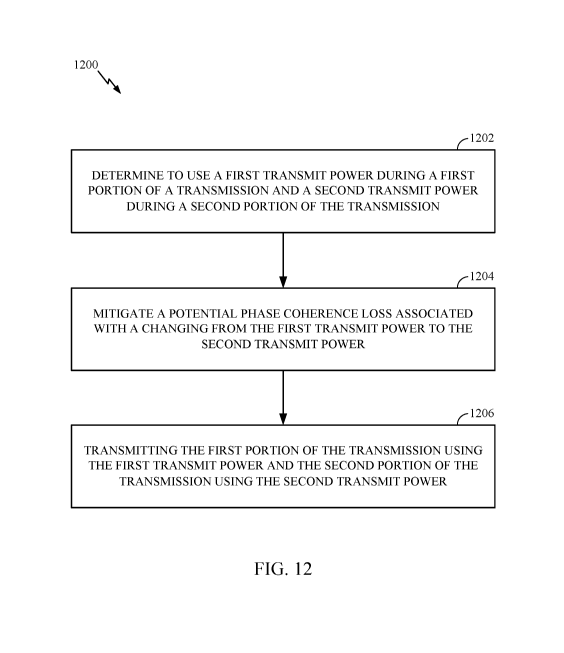
[0029] FIG. 12
illustrates example operations that may be performed by a wireless
device, according to aspects of the present disclosure.
[0030] FIG. 13
illustrates example operations that may be performed by a BS,
according to aspects of the present disclosure.
[0031] To
facilitate understanding, identical reference numerals have been used,
where possible, to designate identical elements that are common to the
figures. It is
contemplated that elements disclosed in one aspect may be beneficially
utilized on other
aspects without specific recitation.
DETAILED DESCRIPTION
[0032] Aspects
of the present disclosure provide apparatus, methods, processing
systems, and computer readable mediums for handling power transitions in new
radio
(NR) wireless communications systems. According to aspects of the present
disclosure
described herein, a device may transmit a transmission with different power
levels for
different portions of the transmission (e.g., different power levels for
reference signals
and data incorporated in an orthogonal frequency domain multiplexing (OFDM)
symbol), and the device may take one or more actions to mitigate a phase
coherence
loss that may result from the changing power level of the transmission. A
phase
coherence loss may cause a receiver to experience difficulty in receiving and
decoding
the transmission, so mitigating the potential phase coherence may improve data
throughput rates and/or reduce error rates of communications.
[0033] Various
aspects of the disclosure are described more fully hereinafter with
reference to the accompanying drawings. This disclosure may, however, be
embodied
in many different forms and should not be construed as limited to any specific
structure
or function presented throughout this disclosure. Rather, these aspects are
provided so
that this disclosure will be thorough and complete, and will fully convey the
scope of
the disclosure to those skilled in the art. Based on the teachings herein one
skilled in the
CA 03073962 2020-02-25
WO 2019/070390
PCT/US2018/051253
7
art should appreciate that the scope of the disclosure is intended to cover
any aspect of
the disclosure disclosed herein, whether implemented independently of or
combined
with any other aspect of the disclosure. For example, an apparatus may be
implemented
or a method may be practiced using any number of the aspects set forth herein.
In
addition, the scope of the disclosure is intended to cover such an apparatus
or method
which is practiced using other structure, functionality, or structure and
functionality in
addition to or other than the various aspects of the disclosure set forth
herein. It should
be understood that any aspect of the disclosure disclosed herein may be
embodied by
one or more elements of a claim.
[0034] The word
"exemplary" is used herein to mean "serving as an example,
instance, or illustration." Any aspect described herein as "exemplary" is not
necessarily
to be construed as preferred or advantageous over other aspects.
[0035] Although
particular aspects are described herein, many variations and
permutations of these aspects fall within the scope of the disclosure.
Although some
benefits and advantages of the preferred aspects are mentioned, the scope of
the
disclosure is not intended to be limited to particular benefits, uses, or
objectives.
Rather, aspects of the disclosure are intended to be broadly applicable to
different
wireless technologies, system configurations, networks, and transmission
protocols,
some of which are illustrated by way of example in the figures and in the
following
description of the preferred aspects. The detailed description and drawings
are merely
illustrative of the disclosure rather than limiting and the scope of the
disclosure is being
defined by the appended claims and equivalents thereof
[0036] The
techniques described herein may be used for various wireless
communication networks such as LTE, CDMA, TDMA, FDMA, OFDMA, SC-FDMA
and other networks. The terms "network" and "system" are often used
interchangeably.
A CDMA network may implement a radio technology such as Universal Terrestrial
Radio Access (UTRA), cdma2000, etc. UTRA includes Wideband CDMA (WCDMA)
and other variants of CDMA. cdma2000 covers IS-2000, IS-95 and IS-856
standards.
A TDMA network may implement a radio technology such as Global System for
Mobile Communications (GSM). An OFDMA network may implement a radio
technology such as NR (e.g. 5G RA), Evolved UTRA (E-UTRA), Ultra Mobile
Broadband (UMB), IEEE 802.11 (Wi-Fi), IEEE 802.16 (WiMAX), IEEE 802.20, Flash-
CA 03073962 2020-02-25
WO 2019/070390
PCT/US2018/051253
8
OFDMA, etc. UTRA and E-UTRA are part of Universal Mobile Telecommunication
System (UMTS). NR is an emerging wireless communications technology under
development in conjunction with the 5G Technology Forum (5GTF). 3GPP Long Term
Evolution (LTE) and LTE-Advanced (LTE-A) are releases of UMTS that use E-UTRA.
UTRA, E-UTRA, UMTS, LTE, LTE-A and GSM are described in documents from an
organization named "3rd Generation Partnership Project" (3GPP). cdma2000 and
UMB
are described in documents from an organization named "3rd Generation
Partnership
Project 2" (3GPP2). The techniques described herein may be used for the
wireless
networks and radio technologies mentioned above as well as other wireless
networks
and radio technologies.
[0037] For
clarity, while aspects may be described herein using terminology
commonly associated with 3G and/or 4G wireless technologies, aspects of the
present
disclosure can be applied in other generation-based communication systems,
such as 5G
and later, including NR technologies.
[0038] New
radio (NR) may refer to radios configured to operate according to a new
air interface (e.g., other than Orthogonal Frequency Divisional Multiple
Access
(OFDMA)-based air interfaces) or fixed transport layer (e.g., other than
Internet
Protocol (IP)). NR may include Enhanced mobile broadband (eMBB) techniques
targeting wide bandwidth (e.g., 80 MHz and wider) communications, millimeter
wave
(mmW) techniques targeting high carrier frequency (e.g., 27 GHz and higher)
communications, massive machine type communications (mMTC) techniques
targeting
non-backward compatible machine type communications (MTC), and mission
critical
techniques targeting ultra reliable low latency communications (URLLC). For
these
general topics, different techniques are considered, such as coding, including
low-
density parity check (LDPC) coding, and polar coding. NR cell may refer to a
cell
operating according to the new air interface or fixed transport layer. A NR
Node B
(e.g., a 5G Node B) may correspond to one or multiple transmission reception
points
(TRPs).
[0039] NR cells
can be configured as access cell (ACells) or data only cells
(DCells). For example, the radio access network (e.g., a central unit or
distributed unit)
can configure the cells. DCells may be cells used for carrier aggregation or
dual
connectivity, but not used for initial access, cell selection/reselection, or
handover. In
CA 03073962 2020-02-25
WO 2019/070390
PCT/US2018/051253
9
some cases DCells may not transmit synchronization signals (SS)¨in some case
cases
DCells may transmit SS. TRPs may transmit downlink signals to UEs indicating
the
cell type. Based on the cell type indication, the UE may communicate with the
TRP.
For example, the UE may determine TRPs to consider for cell selection, access,
handover, and/or measurement based on the indicated cell type.
[0040] In some
cases, the UE can receive measurement configuration from the radio
access network (RAN). The measurement configuration information may indicate
ACells or DCells for the UE to measure. The UE may monitor and/or detect
measurement reference signals (MRS) from the cells based on measurement
configuration information. In some cases, the UE may blindly detect MRS. In
some
cases the UE may detect MRS based on MRS identifiers (MRS-IDs) indicated from
the
RAN. The UE may report the measurement results.
EXAMPLE WIRELESS COMMUNICATIONS SYSTEM
[0041] FIG. 1
illustrates an example wireless network 100 in which aspects of the
present disclosure may be performed. For example, the wireless network may be
a new
radio (NR) or a 5G network.
[0042]
According to aspects, the wireless network 100 may be a heterogeneous
numerology system, wherein UEs 120 within the network 100 may be asynchronous,
have different intercarrier spacing, and/or have different cyclic prefix
lengths.
According to aspects a BS, such as BS 110a may support different services
having
different service requirements. For example, the BS 110a may support subframe
with
different subcarrier spacing. The BS 110a may communicate with UE 120a using a
first
subcarrier spacing and may communicate with UE 120b using a second subcarrier
spacing. UEs 120a, 120b may be configured to operate according to one or more
numerologies. In the manner a network may support subframes with different
subcarrier spacings.
[0043]
According to aspects, the subcarrier spacing associated with the different
service requirements may be scaled. As a non-limiting example, for
illustrative
purposes only, the subcarrier spacing may be 15 kHz, 30 kHz, 60 kHz, 120 kHz,
and so
on (e.g., xl, x2, x4, x8, and so on...). According to another example, the
subcarrier
spacing may be 17.5 kHz, 35 kHz, and so on (e.g., xl, x2, x3, x4, and so on).
Aspects
CA 03073962 2020-02-25
WO 2019/070390
PCT/US2018/051253
described herein provide methods for tone allocation and resource block
definition for
heterogeneous numerology systems, which may be beneficial for scheduling
devices
and communicating with one or more devices in heterogeneous numerology
systems.
[0044] As
described herein, a numerology may be based, at least in part, on a
subcarrier spacing and a shift in frequency. The BS 110a and UE 120a may
communicate using tones determined using a numerology.
Additionally or
alternatively, the BS 110a and 120a may communicate using an RB defined using
a
numerology.
[0045]
According to some aspects of the present disclosure, the UE 120 may change
from using a first transmit power during a first portion of a transmission to
a second
transmit power during a second portion of the transmission and take action to
mitigate a
potential phase coherence loss associated with the changing from the first
transmit
power to the second transmit power, as described herein with reference to FIG.
12.
[0046]
According to some aspects of the present disclosure, the BS 110 may be
configured to transmit a first grant scheduling a UE (e.g., UE 120) to
transmit a first
transmission, wherein the UE changes from using a first transmit power during
a first
portion of the first transmission to a second transmit power during a second
portion of
the first transmission; to transmit a second grant scheduling the UE to
transmit a second
transmission comprising an indication of at least one of the first transmit
power or the
second transmit power; and to receive the first transmission from the UE,
based on the
indication, as described herein with reference to FIG. 13. Furthermore, the BS
110 and
the UE 120 may be configured to perform other aspects described herein, such
as
changing from using a first transmit power during a first portion of a
transmission to a
second transmit during a second portion of the transmission and taking action
to
mitigate a potential phase coherence loss associated with changing the
transmit power,
described below with reference to FIG. 12. The BS may comprise and/or include
a
transmission reception point (TRP).
[0047] The
system illustrated in FIG. 1 may be, for example, a 5G network. The
wireless network 100 may include a number of Node Bs (e.g., eNodeBs, eNBs, 5G
Node B, etc.) 110 and other network entities. A Node B may be a station that
CA 03073962 2020-02-25
WO 2019/070390
PCT/US2018/051253
11
communicates with the UEs and may also be referred to as a base station, an
access
point, or a 5G Node B.
[0048] Each
Node B 110 may provide communication coverage for a particular
geographic area. In 3GPP and NR systems, the term "cell" can refer to a
coverage area
of a Node B and/or a Node B subsystem serving this coverage area, depending on
the
context in which the term is used.
[0049] A Node B
may provide communication coverage for a macro cell, a pico
cell, a femto cell, and/or other types of cell. A macro cell may cover a
relatively large
geographic area (e.g., several kilometers in radius) and may allow
unrestricted access by
UEs with service subscription. A pico cell may cover a relatively small
geographic area
and may allow unrestricted access by UEs with service subscription. A femto
cell may
cover a relatively small geographic area (e.g., a home) and may allow
restricted access
by UEs having association with the femto cell (e.g., UEs in a Closed
Subscriber Group
(CSG), UEs for users in the home, etc.). A Node B for a macro cell may be
referred to
as a macro Node B. A Node B for a pico cell may be referred to as a pico Node
B. A
Node B for a femto cell may be referred to as a femto Node B or a home Node B.
In the
example shown in FIG. 1, the Node Bs 110a, 110b and 110c may be macro Node Bs
for
the macro cells 102a, 102b and 102c, respectively. The Node B 110x may be a
pico
Node B for a pico cell 102x. The Node Bs 110y and 110z may be femto Node Bs
for
the femto cells 102y and 102z, respectively. A Node B may support one or
multiple
(e.g., three) cells.
[0050] The
wireless network 100 may also include relay stations. A relay station is
a station that receives a transmission of data and/or other information from
an upstream
station (e.g., a Node B or a UE) and sends a transmission of the data and/or
other
information to a downstream station (e.g., a UE or a Node B). A relay station
may also
be a UE that relays transmissions for other UEs. In the example shown in FIG.
1,
a relay station 110r may communicate with the Node B 110a and a UE 120r in
order to
facilitate communication between the Node B 110a and the UE 120r. A relay
station
may also be referred to as a relay Node B, a relay, etc.
[0051] The
wireless network 100 may be a heterogeneous network that includes
Node Bs of different types, e.g., macro Node Bs, pico Node Bs, femto Node Bs,
relays,
CA 03073962 2020-02-25
WO 2019/070390
PCT/US2018/051253
12
transmission reception points (TRPs), etc. These different types of Node Bs
may have
different transmit power levels, different coverage areas, and different
impact on
interference in the wireless network 100. For example, macro Node Bs may have
a high
transmit power level (e.g., 20 Watts) whereas pico Node Bs, femto Node Bs and
relays
may have a lower transmit power level (e.g., 1 Watt).
[0052] The
wireless network 100 may support synchronous or asynchronous
operation. For synchronous operation, the Node Bs may have similar frame
timing, and
transmissions from different Node Bs may be approximately aligned in time. For
asynchronous operation, the Node Bs may have different frame timing, and
transmissions from different Node Bs may not be aligned in time. The
techniques
described herein may be used for both synchronous and asynchronous operation.
[0053] A
network controller 130 may couple to a set of Node Bs and provide
coordination and control for these Node Bs. The network controller 130 may
communicate with the Node Bs 110 via a backhaul. The Node Bs 110 may also
communicate with one another, e.g., directly or indirectly via wireless or
wireline
backhaul.
[0054] The UEs
120 (e.g., 120x, 120y, etc.) may be dispersed throughout the
wireless network 100, and each UE may be stationary or mobile. A UE may also
be
referred to as a terminal, a mobile station, a subscriber unit, a station,
etc. A UE may be
a cellular phone, a personal digital assistant (PDA), a wireless modem, a
wireless
communication device, a handheld device, a laptop computer, a cordless phone,
a
wireless local loop (WLL) station, a tablet, a netbook, a smart book, etc. A
UE may be
able to communicate with macro Node Bs, pico Node Bs, femto Node Bs, relays,
etc.
In FIG. 1, a solid line with double arrows indicates desired transmissions
between a UE
and a serving Node B, which is a Node B designated to serve the UE on the
downlink
and/or uplink. A dashed line with double arrows indicates interfering
transmissions
between a UE and a Node B.
[0055] LTE
utilizes orthogonal frequency division multiplexing (OFDM) on the
downlink and single-carrier frequency division multiplexing (SC-FDM) on the
uplink.
OFDM and SC-FDM partition the system bandwidth into multiple (K) orthogonal
subcarriers, which are also commonly referred to as tones, bins, etc. Each
subcarrier
CA 03073962 2020-02-25
WO 2019/070390
PCT/US2018/051253
13
may be modulated with data. In general, modulation symbols are sent in the
frequency
domain with OFDM and in the time domain with SC-FDM. The spacing between
adjacent subcarriers may be fixed, and the total number of subcarriers (K) may
be
dependent on the system bandwidth. For example, the spacing of the subcarriers
may
be 15 kHz and the minimum resource allocation (called a 'resource block') may
be 12
subcarriers (or 180 kHz). Consequently, the nominal FFT size may be equal to
128,
256, 512, 1024 or 2048 for system bandwidth of 1.25, 2.5, 5, 10 or 20
megahertz
(MHz), respectively. The system bandwidth may also be partitioned into
subbands. For
example, a subband may cover 1.08 MHz (i.e., 6 resource blocks), and there may
be
1, 2, 4, 8 or 16 subbands for system bandwidth of 1.25, 2.5, 5, 10 or 20 MHz,
respectively. New radio (NR) may use a different air interface, other than
OFDM-
based. NR networks may include entities such central units or distributed
units.
[0056] While
aspects of the examples described herein may be associated with LTE
technologies, aspects of the present disclosure may be applicable with other
wireless
communications systems, such as NR. NR may utilize OFDM with a CP on the
uplink
and downlink and include support for half-duplex operation using TDD. A single
component carrier bandwidth of 100 MHZ may be supported. NR resource blocks
may
span 12 sub-carriers with a sub-carrier bandwidth of 75 kHz over a 0.1 ms
duration.
Each radio frame may consist of 2 half frames, each half frame consisting of 5
subframes, with a length of 10 ms. Consequently, each subframe may have a
length of
1 ms. Each subframe may indicate a link direction (i.e., DL or UL) for data
transmission and the link direction for each subframe may be dynamically
switched.
Each subframe may include DL/UL data as well as DL/UL control data.
Beamforming
may be supported and beam direction may be dynamically configured. MIMO
transmissions with precoding may also be supported. MIMO configurations in the
DL
may support up to 8 transmit antennas with multi-layer DL transmissions up to
8
streams and up to 2 streams per UE. Multi-layer transmissions with up to 2
streams per
UE may be supported. Aggregation of multiple cells may be supported with up to
8
serving cells. Alternatively, NR may support a different air interface, other
than an
OFDM-based. NR networks may include entities such central units or distributed
units.
[0057] FIG. 2
shows a down link (DL) frame structure used in a telecommunication
systems (e.g., LTE). The transmission timeline for the downlink may be
partitioned
CA 03073962 2020-02-25
WO 2019/070390
PCT/US2018/051253
14
into units of radio frames. Each radio frame may have a predetermined duration
(e.g.,
milliseconds (ms)) and may be partitioned into 10 sub-frames with indices of
0 through 9. Each sub-frame may include two slots. Each radio frame may thus
include
slots with indices of 0 through 19. Each slot may include L symbol periods,
e.g., 7
symbol periods for a normal cyclic prefix (as shown in FIG. 2) or 6 symbol
periods for
an extended cyclic prefix. The 2L symbol periods in each sub-frame may be
assigned
indices of 0 through 2L-1. The available time frequency resources may be
partitioned
into resource blocks. Each resource block may cover N subcarriers (e.g., 12
subcarriers)
in one slot.
[0058] In LTE,
a Node B may send a primary synchronization signal (PSS) and a
secondary synchronization signal (SSS) for each cell in the Node B. The
primary and
secondary synchronization signals may be sent in symbol periods 6 and 5,
respectively,
in each of sub-frames 0 and 5 of each radio frame with the normal cyclic
prefix, as
shown in FIG. 2. The synchronization signals may be used by UEs for cell
detection
and acquisition. The Node B may send a Physical Broadcast Channel (PBCH) in
symbol periods 0 to 3 in slot 1 of sub-frame 0. The PBCH may carry certain
system
information.
[0059] The Node
B may send a Physical Control Format Indicator Channel
(PCFICH) in only a portion of the first symbol period of each sub-frame,
although
depicted in the entire first symbol period in FIG. 2. The PCFICH may convey
the
number of symbol periods (M) used for control channels, where M may be equal
to 1, 2
or 3 and may change from sub-frame to sub-frame. M may also be equal to 4 for
a
small system bandwidth, e.g., with less than 10 resource blocks. In the
example shown
in FIG. 2, M=3. The Node B may send a Physical HARQ Indicator Channel (PHICH)
and a Physical Downlink Control Channel (PDCCH) in the first M symbol periods
of
each sub-frame (M=3 in FIG. 2). The PHICH may carry information to support
hybrid
automatic retransmission (HARQ). The PDCCH may carry information on uplink and
downlink resource allocation for UEs and power control information for uplink
channels. Although not shown in the first symbol period in FIG. 2, it is
understood that
the PDCCH and PHICH are also included in the first symbol period. Similarly,
the
PHICH and PDCCH are also both in the second and third symbol periods, although
not
shown that way in FIG. 2. The Node B may send a Physical Downlink Shared
Channel
CA 03073962 2020-02-25
WO 2019/070390
PCT/US2018/051253
(PDSCH) in the remaining symbol periods of each sub-frame. The PDSCH may carry
data for UEs scheduled for data transmission on the downlink. The various
signals and
channels in LTE are described in 3GPP TS 36.211, entitled "Evolved Universal
Terrestrial Radio Access (E-UTRA); Physical Channels and Modulation," which is
publicly available.
[0060] The Node
B may send the PSS, SSS and PBCH in the center 1.08 MHz of
the system bandwidth used by the Node B. The Node B may send the PCFICH and
PHICH across the entire system bandwidth in each symbol period in which these
channels are sent. The Node B may send the PDCCH to groups of UEs in certain
portions of the system bandwidth. The Node B may send the PDSCH to specific
UEs in
specific portions of the system bandwidth. The Node B may send the PSS, SSS,
PBCH,
PCFICH and PHICH in a broadcast manner to all UEs, may send the PDCCH in a
unicast manner to specific UEs, and may also send the PDSCH in a unicast
manner to
specific UEs.
[0061] A number
of resource elements may be available in each symbol period.
Each resource element may cover one subcarrier in one symbol period and may be
used
to send one modulation symbol, which may be a real or complex value. Resource
elements not used for a reference signal in each symbol period may be arranged
into
resource element groups (REGs). Each REG may include four resource elements in
one
symbol period. The PCFICH may occupy four REGs, which may be spaced
approximately equally across frequency, in symbol period 0. The PHICH may
occupy
three REGs, which may be spread across frequency, in one or more configurable
symbol
periods. For example, the three REGs for the PHICH may all belong in symbol
period 0
or may be spread in symbol periods 0, 1 and 2. The PDCCH may occupy 9, 18, 36
or
72 REGs, which may be selected from the available REGs, in the first M symbol
periods. Only certain combinations of REGs may be allowed for the PDCCH.
[0062] A UE may
know the specific REGs used for the PHICH and the PCFICH.
The UE may search different combinations of REGs for the PDCCH. The number of
combinations to search is typically less than the number of allowed
combinations for the
PDCCH. A Node B may send the PDCCH to the UE in any of the combinations that
the UE will search.
CA 03073962 2020-02-25
WO 2019/070390
PCT/US2018/051253
16
[0063] A UE may
be within the coverage of multiple Node Bs. One of these Node
Bs may be selected to serve the UE. The serving Node B may be selected based
on
various criteria such as received power, path loss, signal-to-noise ratio
(SNR), etc.
[0064] FIG. 3
is a diagram 300 illustrating an example of an uplink (UL) frame
structure in a telecommunications system (e.g., LTE). The available resource
blocks for
the UL may be partitioned into a data section and a control section. The
control section
may be formed at the two edges of the system bandwidth and may have a
configurable
size. The resource blocks in the control section may be assigned to UEs for
transmission of control information. The data section may include all resource
blocks
not included in the control section. The UL frame structure results in the
data section
including contiguous subcarriers, which may allow a single UE to be assigned
all of the
contiguous subcarriers in the data section.
[0065] A UE may
be assigned resource blocks 310a, 310b in the control section to
transmit control information to a Node B. The UE may also be assigned resource
blocks 320a, 320b in the data section to transmit data to the Node B. The UE
may
transmit control information in a physical UL control channel (PUCCH) on the
assigned
resource blocks in the control section. The UE may transmit only data or both
data and
control information in a physical UL shared channel (PUSCH) on the assigned
resource
blocks in the data section. A UL transmission may span both slots of a
subframe and
may hop across frequency.
[0066] A set of
resource blocks may be used to perform initial system access and
achieve UL synchronization in a physical random access channel (PRACH) 330.
The
PRACH 330 carries a random sequence and cannot carry any UL data/signaling.
Each
random access preamble occupies a bandwidth corresponding to six consecutive
resource blocks. The starting frequency is specified by the network. That is,
the
transmission of the random access preamble is restricted to certain time and
frequency
resources. There is no frequency hopping for the PRACH. The PRACH attempt is
carried in a single subframe (1 ms) or in a sequence of few contiguous
subframes and a
UE can make only a single PRACH attempt per frame (10 ms).
[0067] FIG. 4
illustrates example components of the base station 110 and UE 120
illustrated in FIG. 1, which may be used to implement aspects of the present
disclosure.
CA 03073962 2020-02-25
WO 2019/070390
PCT/US2018/051253
17
One or more components of the BS 110 and UE 120 may be used to practice
aspects of
the present disclosure. For example, antennas 452, Tx/Rx 222, processors 466,
458,
464, and/or controller/processor 480 of the UE 120 and/or antennas 434,
processors
460, 420, 438, and/or controller/processor 440 of the BS 110 may be used to
perform
the operations described herein and illustrated with reference to FIGs. 12-13.
The BS
110 may comprise a TRP. As illustrated, the BS/TRP 110 and UE 120 may
communicate using tone alignment and/or RB definition in a heterogeneous
numerology
system.
[0068] At the
base station 110, a transmit processor 420 may receive data from a
data source 412 and control information from a controller/processor 440. The
control
information may be for the PBCH, PCFICH, PHICH, PDCCH, etc. The data may be
for
the PDSCH, etc. The transmit processor 420 may process (e.g., encode and
symbol
map) the data and control information to obtain data symbols and control
symbols,
respectively. The transmit processor 420 may also generate reference symbols,
e.g., for
the PSS, SSS, and cell-specific reference signal. A transmit (TX) multiple-
input
multiple-output (MIMO) processor 430 may perform spatial processing (e.g.,
precoding) on the data symbols, the control symbols, and/or the reference
symbols, if
applicable, and may provide output symbol streams to the modulators (MODs)
432a
through 432t. Each modulator 432 may process a respective output symbol stream
(e.g.,
for OFDM, etc.) to obtain an output sample stream. Each modulator 432 may
further
process (e.g., convert to analog, amplify, filter, and upconvert) the output
sample stream
to obtain a downlink signal. Downlink signals from modulators 432a through
432t may
be transmitted via the antennas 434a through 434t, respectively. The transmit
processor
420, TX MIMO processor 430, modulators 432a-432t, and antennas 434a-434t may
be
collectively referred to as a transmit chain of the base station.
[0069] At the
UE 120, the antennas 452a through 452r may receive the downlink
signals from the base station 110 and may provide received signals to the
demodulators
(DEMODs) 454a through 454r, respectively. Each demodulator 454 may condition
(e.g., filter, amplify, downconvert, and digitize) a respective received
signal to obtain
input samples. Each demodulator 454 may further process the input samples
(e.g., for
OFDM, etc.) to obtain received symbols. A MIMO detector 456 may obtain
received
symbols from all the demodulators 454a through 454r, perform MIMO detection on
the
CA 03073962 2020-02-25
WO 2019/070390
PCT/US2018/051253
18
received symbols if applicable, and provide detected symbols. A receive
processor 458
may process (e.g., demodulate, deinterleave, and decode) the detected symbols,
provide
decoded data for the UE 120 to a data sink 460, and provide decoded control
information to a controller/processor 480. The receive processor 458, MIMO
detector
456, demodulators 454a-454r, and antennas 452a-452t may be collectively
referred to as
a receive chain of the UE.
[0070] On the
uplink, at the UE 120, a transmit processor 464 may receive and
process data (e.g., for the PUSCH) from a data source 462 and control
information
(e.g., for the PUCCH) from the controller/processor 480. The transmit
processor 464
may also generate reference symbols for a reference signal. The symbols from
the
transmit processor 464 may be precoded by a TX MIMO processor 466 if
applicable,
further processed by the demodulators 454a through 454r (e.g., for SC-FDM,
etc.), and
transmitted to the base station 110. The transmit processor 464, TX MIMO
processor
466, modulators 454a-454r, and antennas 452a-452r may be collectively referred
to as a
transmit chain of the UE. At the base station 110, the uplink signals from the
UE 120
may be received by the antennas 434, processed by the modulators 432, detected
by a
MIMO detector 436 if applicable, and further processed by a receive processor
438 to
obtain decoded data and control information sent by the UE 120. The receive
processor
438 may provide the decoded data to a data sink 439 and the decoded control
information to the controller/processor 440. The receive processor 438, MIMO
detector
436, demodulators 432a-432t, and antennas 434a-434t may be collectively
referred to as
a receive chain of the base station.
[0071] The
controllers/processors 440 and 480 may direct the operation at the base
station 110 and the UE 120, respectively. The processor 440 and/or other
processors
and modules at the base station 110 may perform or direct, e.g., the execution
of various
processes for the techniques described herein, such as operations 1200 and
1300,
described below with reference to FIGs. 12 and 13. The processor 480 and/or
other
processors and modules at the UE 120 may also perform or direct, e.g., the
execution of
the functional blocks illustrated in FIG. 12, and/or other processes for the
techniques
described herein. The memories 442 and 482 may store data and program codes
for the
base station 110 and the UE 120, respectively. A scheduler 444 may schedule
UEs for
data transmission on the downlink and/or uplink.
CA 03073962 2020-02-25
WO 2019/070390
PCT/US2018/051253
19
[0072] FIG. 5
is a block diagram of an example transceiver front end 500, such as
transceiver front ends 222, 254 in FIG. 2, in which aspects of the present
disclosure may
be practiced. The transceiver front end 500 includes a transmit (TX) path 502
(also
known as a transmit chain) for transmitting signals via one or more antennas
and a
receive (RX) path 504 (also known as a receive chain) for receiving signals
via the
antennas. When the TX path 502 and the RX path 504 share an antenna 503, the
paths
may be connected with the antenna via an interface 506, which may include any
of
various suitable RF devices, such as a duplexer, a switch, a diplexer, and the
like.
[0073]
Receiving in-phase (I) or quadrature (Q) baseband analog signals from a
digital-to-analog converter (DAC) 508, the TX path 502 may include a baseband
filter
(BBF) 510, a mixer 512, a driver amplifier (DA) 514, and a power amplifier
(PA) 516.
The BBF 510, the mixer 512, and the DA 514 may be included in a radio
frequency
integrated circuit (RFIC), while the PA 516 may be external to the RFIC. In
some
aspects of the present disclosure, the BBF 510 may include a tunable active
filter as
described below. The BBF 510 filters the baseband signals received from the
DAC 508,
and the mixer 512 mixes the filtered baseband signals with a transmit local
oscillator
(LO) signal to convert the baseband signal of interest to a different
frequency
(e.g., upconvert from baseband to RF). This frequency conversion process
produces the
sum and difference frequencies of the LO frequency and the frequency of the
signal of
interest. The sum and difference frequencies are referred to as the beat
frequencies.
The beat frequencies are typically in the RF range, such that the signals
output by the
mixer 512 are typically RF signals, which may be amplified by the DA 514
and/or by
the PA 516 before transmission by the antenna 503.
[0074] The RX
path 504 includes a low noise amplifier (LNA) 522, a mixer 524,
and a baseband filter (BBF) 526. In some aspects of the present disclosure,
the BBF
526 may include a tunable active filter as described below. The LNA 522, the
mixer
524, and the BBF 526 may be included in a radio frequency integrated circuit
(RFIC),
which may or may not be the same RFIC that includes the TX path components. RF
signals received via the antenna 503 may be amplified by the LNA 522, and the
mixer
524 mixes the amplified RF signals with a receive local oscillator (LO) signal
to convert
the RF signal of interest to a different baseband frequency (i.e.,
downconvert). The
baseband signals output by the mixer 524 may be filtered by the BBF 526 before
being
CA 03073962 2020-02-25
WO 2019/070390
PCT/US2018/051253
converted by an analog-to-digital converter (ADC) 528 to digital I or Q
signals for
digital signal processing. In certain aspects of the present disclosure, the
PA 516 and/or
LNA 522 may be implemented using a differential amplifier.
[0075] While it
is desirable for the output of an LO to remain stable in frequency,
tuning the LO to different frequencies typically entails using a variable-
frequency
oscillator, which involves compromises between stability and tunability.
Contemporary
systems may employ frequency synthesizers with a voltage-controlled oscillator
(VCO)
to generate a stable, tunable LO with a particular tuning range. Thus, the
transmit LO
frequency may be produced by a TX frequency synthesizer 518, which may be
buffered
or amplified by amplifier 520 before being mixed with the baseband signals in
the mixer
512. Similarly, the receive LO frequency may be produced by an RX frequency
synthesizer 530, which may be buffered or amplified by amplifier 532 before
being
mixed with the RF signals in the mixer 524.
[0076] FIG. 6
is a diagram 600 illustrating an example of a radio protocol
architecture for the user and control planes in LTE. The radio protocol
architecture for
the UE and the Node B is shown with three layers: Layer 1, Layer 2, and Layer
3.
Layer 1 (L1 layer) is the lowest layer and implements various physical layer
signal
processing functions. The Li layer will be referred to herein as the physical
layer 606.
Layer 2 (L2 layer) 608 is above the physical layer 606 and is responsible for
the link
between the UE and Node B over the physical layer 606.
[0077] In the
user plane, the L2 layer 608 includes a media access control (MAC)
sublayer 610, a radio link control (RLC) sublayer 612, and a packet data
convergence
protocol (PDCP) 614 sublayer, which are terminated at the Node B on the
network side.
Although not shown, the UE may have several upper layers above the L2 layer
608
including a network layer (e.g., IP layer) that is terminated at a packet data
network
(PDN) gateway on the network side, and an application layer that is terminated
at the
other end of the connection (e.g., far end UE, server, etc.).
[0078] The PDCP
sublayer 614 provides multiplexing between different radio
bearers and logical channels. The PDCP
sublayer 614 also provides header
compression for upper layer data packets to reduce radio transmission
overhead,
security by ciphering the data packets, and handover support for UEs between
Node Bs.
CA 03073962 2020-02-25
WO 2019/070390
PCT/US2018/051253
21
The RLC sublayer 612 provides segmentation and reassembly of upper layer data
packets, retransmission of lost data packets, and reordering of data packets
to
compensate for out-of-order reception due to hybrid automatic repeat request
(HARQ).
The MAC sublayer 610 provides multiplexing between logical and transport
channels.
The MAC sublayer 610 is also responsible for allocating the various radio
resources
(e.g., resource blocks) in one cell among the UEs. The MAC sublayer 610 is
also
responsible for HARQ operations.
[0079] In the
control plane, the radio protocol architecture for the UE and Node B is
substantially the same for the physical layer 606 and the L2 layer 608 with
the exception
that there is no header compression function for the control plane. The
control plane
also includes a radio resource control (RRC) sublayer 616 in Layer 3 (L3
layer). The
RRC sublayer 616 is responsible for obtaining radio resources (i.e., radio
bearers) and
for configuring the lower layers using RRC signaling between the Node B and
the UE.
[0080] FIG. 7
shows two exemplary subframe formats 710 and 720 for the
downlink with the normal cyclic prefix. The available time frequency resources
for the
downlink may be partitioned into resource blocks. Each resource block may
cover 12
subcarriers in one slot and may include a number of resource elements. Each
resource
element may cover one subcarrier in one symbol period and may be used to send
one
modulation symbol, which may be a real or complex value.
[0081] Subframe
format 710 may be used for a Node B equipped with two antennas.
A CRS may be transmitted from antennas 0 and 1 in symbol periods 0, 4, 7 and
11. A
reference signal is a signal that is known a priori by a transmitter and a
receiver and
may also be referred to as a pilot. A CRS is a reference signal that is
specific for a cell,
e.g., generated based on a cell identity (ID). In FIG. 7, for a given resource
element
with label Ra, a modulation symbol may be transmitted on that resource element
from
antenna a, and no modulation symbols may be transmitted on that resource
element
from other antennas. Subframe format 720 may be used for a Node B equipped
with
four antennas. A CRS may be transmitted from antennas 0 and 1 in symbol
periods 0,
4, 7 and 11 and from antennas 2 and 3 in symbol periods 1 and 8. For both
subframe
formats 710 and 720, a CRS may be transmitted on evenly spaced subcarriers,
which
may be determined based on cell ID. Different Node Bs may transmit their CRSs
on the
same or different subcarriers, depending on their cell IDs. For both subframe
formats
CA 03073962 2020-02-25
WO 2019/070390
PCT/US2018/051253
22
710 and 720, resource elements not used for the CRS may be used to transmit
data (e.g.,
traffic data, control data, and/or other data).
[0082] The PSS,
SSS, CRS and PBCH in LTE are described in 3GPP TS 36.211,
entitled "Evolved Universal Terrestrial Radio Access (E-UTRA); Physical
Channels and
Modulation," which is publicly available.
[0083] An
interlace structure may be used for each of the downlink and uplink for
FDD in LTE. For example, Q interlaces with indices of 0 through Q ¨1 may be
defined, where Q may be equal to 4, 6, 8, 10, or some other value. Each
interlace may
include subframes that are spaced apart by Q frames. In particular, interlace
q may
include subframes q, q + Q , q + 2Q , etc., where q E {0, Q ¨1}.
[0084] The
wireless network may support hybrid automatic retransmission (HARQ)
for data transmission on the downlink and uplink. For HARQ, a transmitter
(e.g., a
Node B) may send one or more transmissions of a packet until the packet is
decoded
correctly by a receiver (e.g., a UE) or some other termination condition is
encountered.
For synchronous HARQ, all transmissions of the packet may be sent in subframes
of a
single interlace. For asynchronous HARQ, each transmission of the packet may
be sent
in any subframe.
[0085] A UE may
be located within the coverage area of multiple Node Bs. One of
these Node Bs may be selected to serve the UE. The serving Node B may be
selected
based on various criteria such as received signal strength, received signal
quality,
pathloss, etc. Received signal quality may be quantified by a signal-to-noise-
and-
interference ratio (SINR), or a reference signal received quality (RSRQ), or
some other
metric. The UE may operate in a dominant interference scenario in which the UE
may
observe high interference from one or more interfering Node Bs.
[0086] NR cell
may refer to a cell operating according in the NR network. A NR
Node B (e.g., Node B 110) may correspond to one or multiple transmission
reception
points (TRPs). As used herein, a cell may refer to a combination of downlink
(and
potentially also uplink) resources. The linking between the carrier frequency
of the
downlink resources and the carrier frequency of the uplink resources is
indicated in the
system information (SI) transmitted on the downlink resources. For example,
system
CA 03073962 2020-02-25
WO 2019/070390
PCT/US2018/051253
23
information can be transmitted in a physical broadcast channel (PBCH) carrying
a
master information block (MIB).
[0087] NR RAN
architecture may include a central unit (CU) (e.g., network
controller 130). The CU may be an Access node controller (ANC). The CU
terminates
backhaul interface to RAN-CN, terminates backhaul interface to neighbor RAN
node.
The RAN may include a Distributed unit that may be one or more TRPs that may
be
connected to one or more ANCs (not shown). TRPs may advertise System
Information
(e.g., Global TRP ID), may include PDCP/RLC/MAC functions, may comprise one or
more antenna ports, may be configured to individually (dynamic selection) or
jointly
(joint transmission), and may serve traffic to the UE.
[0088]
Heterogeneous numerology wireless communication systems may refer to
systems in which UEs may be asynchronous, have different intercarrier spacing
and/or
have different cyclic prefix lengths. According to aspects of the present
disclosure,
tones for different numerologies may be aligned. A numerology may be based on
a
subcarrier spacing and a tone shift. As described herein, regardless of the
numerology,
the tones from the heterogeneous numerology wireless systems may be frequency-
aligned.
[0089]
According to aspects of the present disclosure, in a beamforming system, a
broadcast signal transmitted in a particular direction (e.g., from a BS) may
only reach a
subset of UEs or other devices. For dynamic TDD operation, a transmitter may
transmit
a slot or frame format indicator to indicate the slot or frame structure for
the next N slots
or subframes. However, multiple users (e.g., UEs, BSs) may be scheduled in the
N slots
or subframes, and the users may share the transmission resources (e.g., the
available
frequencies for the N slots or subframes) by using TDM or FDM. Those users may
have different beamforming or beam pairing association(s) with a transmitter,
such as an
eNB or a gNB. The transmitter (e.g., a BS, an eNB, a gNB) may transmit a slot
or
frame format indicator in a few OFDM symbols at the beginning of the N slots
or
subframes. For non-beamforming systems, transmitting one such indicator (e.g.,
broadcast to all devices in range) may be sufficient.
[0090] FIG. 8
is a diagram 800 showing an example of a DL-centric subframe. The
DL-centric subframe may include a control portion 802. The control portion 802
may
CA 03073962 2020-02-25
WO 2019/070390
PCT/US2018/051253
24
exist in the initial or beginning portion of the DL-centric subframe. The
control portion
802 may include various scheduling information and/or control information
corresponding to various portions of the DL-centric subframe. In some
configurations,
the control portion 802 may be a physical DL control channel (PDCCH), as
indicated in
FIG. 8. The DL-centric subframe may also include a DL data portion 804. The DL
data
portion 804 may sometimes be referred to as the payload of the DL-centric
subframe.
The DL data portion 804 may include the communication resources utilized to
communicate DL data from the scheduling entity (e.g., UE or BS) to the
subordinate
entity (e.g., UE). In some configurations, the DL data portion 804 may be a
physical
DL shared channel (PDSCH).
[0091] The DL-
centric subframe may also include a common UL portion 806. The
common UL portion 806 may sometimes be referred to as an UL burst, a common UL
burst, and/or various other suitable terms. The common UL portion 806 may
include
feedback information corresponding to various other portions of the DL-centric
subframe. For example, the common UL portion 806 may include feedback
information
corresponding to the control portion 802. Non-limiting examples of feedback
information may include an ACK signal, a NACK signal, a HARQ indicator, and/or
various other suitable types of information. The common UL portion 806 may
include
additional or alternative information, such as information pertaining to
random access
channel (RACH) procedures, scheduling requests (SRs), and various other
suitable
types of information. As illustrated in FIG. 8, the end of the DL data portion
804 may
be separated in time from the beginning of the common UL portion 806 by a
guard
period 808. This guard period may sometimes be referred to as a gap, a guard
interval,
and/or various other suitable terms. This guard period provides time for the
switch-over
from DL communication (e.g., reception operation by the subordinate entity
(e.g., UE))
to UL communication (e.g., transmission by the subordinate entity (e.g., UE)).
One of
ordinary skill in the art will understand that the foregoing is merely one
example of a
DL-centric subframe and alternative structures having similar features may
exist
without necessarily deviating from the aspects described herein.
[0092] FIG. 9
is a diagram 900 showing an example of an UL-centric subframe.
The UL -centric subframe may include a control portion 902. The control
portion 902
may exist in the initial or beginning portion of the UL-centric subframe. The
control
CA 03073962 2020-02-25
WO 2019/070390
PCT/US2018/051253
portion 902 in FIG. 9 may be similar to the control portion described above
with
reference to FIG. 8. The UL-centric subframe may also include an UL data
portion 904.
The UL data portion 904 may sometimes be referred to as the payload of the UL-
centric
subframe. The UL portion may refer to the communication resources utilized to
communicate UL data from the subordinate entity (e.g., UE) to the scheduling
entity
(e.g., UE or BS). In some configurations, the control portion 902 may be a
physical DL
control channel (PDCCH).
[0093] As
illustrated in FIG. 9, the end of the control portion 902 may be separated
in time from the beginning of the UL data portion 904 by a guard period 908.
This time
separation may sometimes be referred to as a gap, guard period, guard
interval, and/or
various other suitable terms. This separation provides time for the switch-
over from DL
communication (e.g., reception operation by the scheduling entity) to UL
communication (e.g., transmission by the scheduling entity). The UL-centric
subframe
may also include a common UL portion 906. The common UL portion 906 in FIG. 9
may be similar to the common UL portion 806 described above with reference to
FIG.
8. The common UL portion 906 may additional or alternative include information
pertaining to channel quality indicator (CQI), sounding reference signals
(SRSs), and
various other suitable types of information. One of ordinary skill in the art
will
understand that the foregoing is merely one example of an UL-centric subframe
and
alternative structures having similar features may exist without necessarily
deviating
from the aspects described herein.
[0094] In some
circumstances, two or more subordinate entities (e.g., UEs) may
communicate with each other using sidelink signals. Real-world applications of
such
sidelink communications may include public safety, proximity services, UE-to-
network
relaying, vehicle-to-vehicle (V2V) communications, Internet of Everything
(IoE)
communications, IoT communications, mission-critical mesh, and/or various
other
suitable applications. Generally, a sidelink signal may refer to a signal
communicated
from one subordinate entity (e.g., UE1) to another subordinate entity (e.g.,
UE2)
without relaying that communication through the scheduling entity (e.g., UE or
BS),
even though the scheduling entity may be utilized for scheduling and/or
control
purposes. In some examples, the sidelink signals may be communicated using a
CA 03073962 2020-02-25
WO 2019/070390
PCT/US2018/051253
26
licensed spectrum (unlike wireless local area networks, which typically use an
unlicensed spectrum).
[0095] A UE may
operate in various radio resource configurations, including a
configuration associated with transmitting pilots using a dedicated set of
resources (e.g.,
a radio resource control (RRC) dedicated state, etc.) or a configuration
associated with
transmitting pilots using a common set of resources (e.g., an RRC common
state, etc.).
When operating in the RRC dedicated state, the UE may select a dedicated set
of
resources for transmitting a pilot signal to a network. When operating in the
RRC
common state, the UE may select a common set of resources for transmitting a
pilot
signal to the network. In either case, a pilot signal transmitted by the UE
may be
received by one or more network access devices, such as an AN, or a DU, or
portions
thereof Each receiving network access device may be configured to receive and
measure pilot signals transmitted on the common set of resources, and also
receive and
measure pilot signals transmitted on dedicated sets of resources allocated to
the UEs for
which the network access device is a member of a monitoring set of network
access
devices for the UE. One or more of the receiving network access devices, or a
CU to
which receiving network access device(s) transmit the measurements of the
pilot
signals, may use the measurements to identify serving cells for the UEs, or to
initiate a
change of serving cell for one or more of the UEs.
EXAMPLE HANDLING POWER TRANSITIONS IN NEW RADIO
[0096] It may
be desirable for transmitters in an NR (e.g., 5th Generation
Technology Forum (5GTF)) wireless communications system to change a power
level
in the middle of transmissions. Changing a power level in the middle of a
transmission
may cause a loss of phase coherence (e.g., of the transmitted waveform). For
example,
phase coherence may be lost if a power change is not implemented digitally,
but is
instead implemented via a change in an analog gain stage(s) of a transmit
chain. Loss of
phase coherence may be more severe in uplink (UL) transmissions than in
downlink
(DL) transmissions, because mobile devices (e.g., UEs) may have implementation
constraints that base stations (e.g., next generation NodeBs (gNBs)) do not
have. For
example, an amount of digital gain that a mobile device can generate may be
less than
an amount of digital gain that a base station can generate.
CA 03073962 2020-02-25
WO 2019/070390
PCT/US2018/051253
27
[0097]
According to aspects of the present disclosure described herein, a device
(e.g., a UE or a BS) may transmit a transmission with different power levels
for
different portions of the transmission (e.g., different power levels for
reference signals
and data incorporated in an orthogonal frequency domain multiplexing (OFDM)
symbol), and the device may take one or more actions to mitigate a phase
coherence
loss that may result from the changing power level of the transmission. A
phase
coherence loss may cause a receiver to experience difficulty in receiving and
decoding
the transmission, so mitigating the potential phase coherence loss may improve
data
throughput rates and/or reduce error rates of communications.
[0098] FIGs.
10A-10C illustrate exemplary transmission timelines 1000, 1020, and
1050 illustrative of potential problems that can occur when a device transmits
a
transmission with different power levels, according to aspects of the present
disclosure.
In the exemplary timeline 1000, an exemplary ideal waveform 1004 is
transmitted in a
transmission time interval (TTI) 1002 by an idealized (i.e., not an actual)
transmitter. It
may be noted that the idealized transmitter does not transmit outside of the
TTI 1002 in
the exemplary timeline 1000. An idealized transmitter generates the ideal
waveform
1004 beginning at 1006 and ending at 1008, while any waveforms generated
before
1006 or after 1008 (i.e. in TTIs other than TTI 1002) are completely
unaffected by the
transmitter's activity during TTI 1002, i.e., any waveforms generated before
1006 or
after 1008 are completely independent of the waveform 1004.
[0099] In the
exemplary timeline 1020 shown in FIG. 10B, an exemplary waveform
1024 is transmitted by an exemplary transmitter (i.e., an actual transmitter,
such as a
transmitter in UE 120, shown in FIGs. 1 and 4, and not an idealized
transmitter, as
referred to in FIG. 10A) in the TTI 1002. The exemplary transmitter makes a
spurious
transmission 1022 before the TTI 1002 begins at 1006, for example, when
various
components of the transmitter are ramping up to a desired power level. It may
be noted
that the waveform 1024 is similar to the waveform 1004, shown in FIG. 10A, but
the
transmitter transmits the spurious transmission 1022 outside of the TTI.
[0100] In the
exemplary timeline 1050 shown in FIG. 10C, an exemplary waveform
1054 is transmitted by an exemplary transmitter (i.e., an actual transmitter,
such as a
transmitter in UE 120, shown in FIGs. 1 and 4, and not an idealized
transmitter, as
referred to in FIG. 10A) in the TTI 1002. The exemplary transmitter makes a
spurious
CA 03073962 2020-02-25
WO 2019/070390
PCT/US2018/051253
28
transmission 1052 during the TTI 1002 (i.e., after the TTI begins at 1006),
for example,
when various components of the transmitter are ramping up to a desired power
level. It
may be noted that the waveform 1054 differs from the waveform 1004, shown in
FIG.
10A, due to the spurious transmission 1052, but the transmitter does not
transmit
outside (i.e., before the beginning 1006 or after the end 1008) of the TTI.
[0101] FIG. 11
is a diagram 1100 illustrating an example of an UL transmission
(e.g., a PUSCH), according to aspects of the present disclosure. A UE may
transmit an
uplink transmission in a slot 1102 on a set of subcarriers 1104. A resource
grid may be
used to represent resource elements of a resource block. As illustrated, a
resource block
may contain 12 consecutive subcarriers in the frequency domain and 7
consecutive
OFDM symbols in the time domain, or 84 resource elements. As illustrated at
1106, the
UE may transmit reference signals (e.g., DMRS) on some resource elements of an
OFDM symbol, while leaving other REs of the OFDM symbol blank. The UE may
transmit data on some or all of the other REs, as shown at 1108.
[0102] In the
exemplary timeline 1120, the UE leaves the beginning of the first RE
1122 blank, as exemplified by the straight line at 1130. The UE transmits an
exemplary
waveform 1132 to convey the data of the second RE 1124. Due to the transition
from
the first (blank) RE 1122 to the second (data) RE 1124, the UE makes a
spurious
transmission 1134 before the second RE begins at 1126, for example, when
various
components of a transmitter of the UE are ramping up to a desired power level,
similar
to the spurious transmission shown in FIG. 10B, described above. The spurious
transmission 1134 may interfere with other transmissions that are occurring in
that same
RE or cause a loss of phase coherence in the transmitted waveform, but does
not alter
the data transmitted in the RE 1124.
[0103] In the
exemplary timeline 1150 the UE leaves the first RE 1152 blank, as
exemplified by the straight line at 1160. The UE transmits an exemplary wave
form
1164 to convey the data of the second RE 1154. Due to the transition from the
first
(blank) RE 1152 to the second (data) RE 1154, the UE makes a spurious
transmission
1164 at the beginning 1156 of the second RE, for example, when various
components of
a transmitter of the UE are ramping up to a desired power level, similar to
the spurious
transmission shown in FIG. 10C, described above. The spurious transmission
1164 may
CA 03073962 2020-02-25
WO 2019/070390
PCT/US2018/051253
29
cause a loss of phase coherence in the transmitted waveform or a loss of some
data in
the transmission, but does not interfere with other transmissions in the RE
1152.
[0104] Thus, a
UE transmitting the exemplary uplink transmission illustrated in
FIG. 11 may generate a spurious transmission in an RE that the UE should leave
blank,
possibly interfering with transmissions by other UEs on that RE, or the UE may
generate a spurious transmission in an RE in which the UE is transmitting
data, possibly
causing a receiver of the transmission to misinterpret the data, e.g., by
failing to decode
the transmission. In both cases, the sudden change in the power level of the
transmission may cause a loss of phase coherence in the generated waveform.
[0105] It
should be noted that, due to the much shorter slot-lengths used in NR
communications systems as compared to previously known communications systems,
the spurious transmissions described above may occur in a larger portion of an
RE than
if the same transmitter were transmitting in previously known (e.g., LTE)
communications systems.
[0106]
According to aspects of the present disclosure, a wireless device may
mitigate phase coherence loss related to sudden transitions in transmit power
in a
transmission by manipulating digital gains in a digital portion of a transmit
chain, while
leaving analog gains in an analog portion of the transmit chain unchanged.
[0107] FIG. 12
illustrates example operations 1200 for wireless communications
that may be performed by a wireless device, according to aspects of the
present
disclosure. The UE may be UE 120 or BS 110, shown in FIG. 1, which may include
one or more components illustrated in FIG. 4.
[0108]
Operations 1200 begin at block 1202 with the wireless device determining to
use a first transmit power during a first portion of a transmission and a
second transmit
power during a second portion of the transmission. For example, UE 120 (shown
in
FIG. 1) determines to use a first transmit power during a first portion of a
PUSCH (e.g.,
a blank RE in a symbol period containing a demodulation reference signal
(DMRS) on
other REs of the symbol period) and a second transmit power (e.g., higher than
the first
transmit power) during a second portion of the PUSCH (e.g., an RE containing
data).
CA 03073962 2020-02-25
WO 2019/070390
PCT/US2018/051253
[0109] At block
1204, operations 1200 continue with the wireless device mitigating
a potential phase coherence loss associated with a changing from the first
transmit
power to the second transmit power. Continuing the example from above, UE 120
mitigates (e.g., increasing digital gains associated with the REs in the
symbol period
containing the blank REs and DMRS so as to allow analog gains of a transmit
chain to
remain unchanged from symbol period to symbol period; or selecting a sequence
with a
low peak-to-average-power-ratio (PAPR) for the DMRS) a potential phase
coherence
loss associated with a changing from the first transmit power to the second
transmit
power).
[0110]
Operations 1200 continue at block 1206 with the wireless device
transmitting the first portion of the transmission using the first transmit
power and the
second portion of the transmission using the second transmit power. Continuing
the
example from above, UE 120 transmits the first portion of the PUSCH (e.g., the
blank
RE in the symbol period containing the DMRS on other REs of the symbol period)
using the first transmit power and the second portion of the PUSCH (e.g., the
RE
containing data) using the second transmit power.
[0111] FIG. 13
illustrates example operations 1300 for wireless communications
that may be performed by a wireless device, according to aspects of the
present
disclosure. The wireless device may be BS 110 shown in FIG. 1 or a UE that
schedules
communications for other UEs (e.g., in device-to-device communications), which
may
include one or more components illustrated in FIG. 4.
[0112]
Operations 1300 begin at block 1302 with the wireless device transmitting a
first grant scheduling a UE to transmit a first transmission, wherein the UE
changes
from using a first transmit power during a first portion of the first
transmission to a
second transmit power during a second portion of the first transmission. For
example,
BS 110 (shown in FIG. 1) transmits a first grant scheduling UE 120 to transmit
a first
transmission (e.g., a PUSCH), wherein the UE changes from using a first
transmit
power during a first portion of the first transmission (e.g., an RE containing
data) to a
second transmit power during a second portion of the first transmission (e.g.,
an RE
containing a DMRS).
CA 03073962 2020-02-25
WO 2019/070390
PCT/US2018/051253
31
[0113] At block
1304, operations 1300 continue with the wireless device
transmitting a second grant scheduling the UE to transmit a second
transmission
comprising an indication of at least one of the first transmit power or the
second
transmit power. Continuing the example from above, the BS 110 transmits a
second
grant scheduling the UE 120 to transmit a second transmission (e.g., a PUCCH)
comprising an indication (e.g., a bit in a field of the PUCCH) of the first
transmit power
(e.g., the transmit power of the RE containing the data).
[0114]
Operations 1300 continue at block 1306 with the wireless device receiving
the first transmission from the UE, based on the indication. Continuing the
example
from above, the BS 110 receives the PUSCH from UE 120, based on the indication
of
the first transmit power from block 1304. That is, the BS receives the PUSCH
based on
the transmit power indicated by the UE in the second transmission that is
scheduled by
the second grant.
[0115]
According to aspects of the present disclosure, in NR wireless
communications systems, in some OFDM symbols, certain REs have to be left
empty
(i.e., transmitted with zero power). Transmitting an OFDM symbol with some REs
left
empty may be an example of changing from using a first transmit power during a
first
portion of a transmission to a second transmit power during a second portion
of the
transmission, as described above with reference to block 1202 in FIG. 12. For
example,
some REs may be occupied by transmissions by other UEs, such as comb-based SRS
transmission, wherein a UE may be assigned all combs on one OFDM symbol but a
subset of the combs on the next OFDM symbol. In another example, some REs may
be
reserved for forward compatibility, and UEs following future versions of the
air-
interface specifications may use the reserved REs. In yet another example,
some REs
may be reserved for ultra-reliable low latency communications (URLLC)
transmission(s) by other UEs.
[0116] In
aspects of the present disclosure, if some REs of a transmission are
blanked while other REs are sent without any change, overall transmit power in
the
OFDM symbol is different from transmit power of OFDM symbols without any
blanking. This difference in transmit power has a potential to cause a phase
discontinuity (e.g., a phase coherence loss, as mentioned above in block 1204
in
FIG. 12) in transmissions by a device.
CA 03073962 2020-02-25
WO 2019/070390
PCT/US2018/051253
32
[0117]
According to aspects of the present disclosure, a transmitting device may
blank an entire OFDM symbol, if certain REs of the OFDM symbol have to be
blanked.
Blanking an entire OFDM symbol may be an example of taking action to mitigate
a
potential phase coherence loss associated with the changing from the first
transmit
power to the transmit power, as described above with reference to block 1204
in
FIG. 12.
[0118] In
aspects of the present disclosure, blanking of an entire OFDM symbol
may be done digitally (e.g., in a digital domain symbol, such as the I and Q
digital
signals obtained by the DAC 508 shown in FIG. 5) by a wireless device.
Blanking an
entire OFDM symbol digitally may result in no loss of phase coherence, because
other
components of a transmit chain remain energized at a same energy level.
However,
blanking an entire OFDM symbol may waste transmission resources.
[0119]
According to aspects of the present disclosure, there may be some residual
transmit power transmitted from analog components (e.g., the PA) of a transmit
chain of
a device that digitally blanks an entire OFDM symbol.
[0120] In
aspects of the present disclosure, communications systems operating
according to disclosed techniques may use new rules limiting these emissions
(e.g.,
residual transmit power) that may be more relaxed than the transmit power
limits when
the UE is more "fully" turned off (i.e., off for longer contiguous time
durations).
[0121]
According to aspects of the present disclosure, a transmitting device may
blank REs in a digital domain signal prior to converting the digital domain
signal to an
analog domain signal for transmission. Blanking REs in a digital domain signal
prior to
converting the digital domain signal to an analog domain signal for
transmission may be
an example of taking action to mitigate a potential phase coherence loss
associated with
the changing from the first transmit power to the transmit power, as described
above
with reference to block 1204 in FIG. 12. If a device blanks REs in a digital
domain,
though a total transmit power changes, analog gains of the transmit chain are
unchanged, resulting in no loss of phase coherence. This may cause suboptimal
analog
gain settings for the resulting transmit power. The suboptimal analog gain
setting may
impact quality (e.g., calculation of error vector magnitude (EVM)) of the
resulting
transmission.
CA 03073962 2020-02-25
WO 2019/070390
PCT/US2018/051253
33
[0122]
According to aspects of the present disclosure, a transmitting device may
boost power of un-blanked REs in a digital domain signal prior to converting
the digital
domain signal to an analog domain signal for transmission, in order to
preserve overall
transmit power at a consistent level. Boosting power of un-blanked REs in a
digital
domain signal prior to converting the digital domain signal to an analog
domain signal
for transmission may be an example of taking action to mitigate a potential
phase
coherence loss associated with the changing from the first transmit power to
the second
transmit power, as described above with reference to block 1204 in FIG. 12.
Boosting
power of un-blanked REs in a digital domain signal may result in analog gains
of a
transmit chain of the device remaining unchanged and total transmit power of
the
transmission being unchanged from symbol period to symbol period. If analog
gains of
the transmit chain remain unchanged, then there may be no loss of phase
coherence. In
aspects of the present disclosure, boosting power of un-blanked REs may not
always be
possible, for example, if digital domain gains of a transmitting device are
already at
their maximum settings.
[0123] In
aspects of the present disclosure, a device taking action to mitigate a
potential phase coherence loss may use a combination of the techniques
described
earlier. For example, a device may always boost the power of unblanked REs to
keep
total power unchanged, regardless of whether or not such boosting can be done
purely
digitally, by incurring some possible performance loss due to loss of phase
coherence
whenever digital boosting is infeasible. In such a case, the receiving device
knows the
power level of the OFDM symbols containing the blanked REs relative to other
OFDM
symbols without blanked REs. In another example, a transmitting device may
boost
power only to the extent possible digitally (e.g., to the maximum setting of
the digital
domain gains) and keep analog gains unchanged. A receiving device may not then
know the amount of boost applied, as the receiver is typically unaware of
digital settings
at the transmitter.
[0124]
According to aspects of the present disclosure, digital domain gain settings
of a transmitting device may be dynamic, depending on a current transmission
power
level and other factors, such as TX chain selection across multiple radio
access
technologies (RATs) at the transmitter.
CA 03073962 2020-02-25
WO 2019/070390
PCT/US2018/051253
34
[0125] In
aspects of the present disclosure, a transmitting device may signal a level
of transmit power boost applied to a transmission to an intended receiver of
the
transmission. Signaling of a level of transmit power may be important to a
receiver for
certain types of transmissions. For example, for SRS transmissions, the
relative
transmit power boosts applied on different OFDM symbols are used by a receiver
of the
SRS to compare channel quality estimated from the SRS. In another example, for
data
transmissions, especially long ones, a change in power level for one OFDM
symbol
may be less important for the receiver to know about.
[0126]
According to aspects of the present disclosure, signaling of transmit power
levels may be made in a different transmission time interval (TTI) than the
transmission
with the boosted transmit power levels. For example, if SRS processing (e.g.,
by a base
station) is not time-critical, then SRS transmit power levels may be indicated
in a
suitable 'nearby in time' PUCCH transmission from a transmitting UE.
[0127] In
aspects of the present disclosure, if there is no 'nearby in time' PUCCH or
UL control transmission for a UE to use to signal a transmit power level, then
a PUCCH
or other UL control transmission for signaling transmit power levels may be
scheduled
explicitly by a base station. Explicit scheduling of UL control transmissions
for
signaling transmit power levels may require extra overhead.
[0128]
According to aspects of the present disclosure, signaling of transmit power
levels may be enabled and/or disabled, depending on a transmission type of the
transmission, including waveform, transmission contents, and transmission
power of the
transmission.
[0129]
According to aspects of the present disclosure, transmitting using pi/2 binary
phase shift keying (pi/2-BPSK or 11/2-BPSK) modulation together with a
discrete
Fourier transform single-carrier orthogonal frequency division multiplexing
(DFT-s-
OFDM) waveform has a significantly lower peak-to-average-power-ratio (PAPR)
than
transmitting using quadrature phase shift keying (QPSK) modulation.
Transmitting
with pi/2-BPSK modulation and a DFT-s-OFDM waveform also has a lower PAPR than
Zadoff-Chu sequences chosen explicitly for their low PAPR for demodulation
reference
signals (DMRS) in LTE UL transmissions.
CA 03073962 2020-02-25
WO 2019/070390
PCT/US2018/051253
[0130] In
aspects of the present disclosure, re-using Zadoff-Chu sequences for
DMRS transmissions may require special handling, because of the Zadoff-Chu
sequences having a higher PAPR than a pi/2-BPSK DFT-s-OFDM waveform used for
conveying data in a same period as the DMRS.
[0131] In
aspects of the present disclosure, if a new radio transmitting device uses a
Zadoff-Chu sequence for DMRS transmissions (e.g., similar to an LTE
transmitting
device), the transmitting device may apply a different power amplifier (PA)
back-off for
DMRS (e.g., DMRS based on Zadoff-Chu sequences that have a higher PAPR than a
pi/2-BPSK DFT-s-OFDM waveform) REs in a transmission than the transmitting
device
uses for REs conveying data in the transmission. This may result in a
different transmit
power for REs conveying data and for DMRS in the transmission, again possibly
causing a phase discontinuity (e.g., loss of phase coherence) in the
transmission.
[0132]
According to aspects of the present disclosure, the same techniques
described above (e.g., blanking of an entire OFDM symbol in the digital domain
or by
other techniques, blanking REs in a digital domain signal prior to converting
the digital
domain signal to an analog domain signal, and/or boosting power of un-blanked
REs in
a digital domain signal prior to converting the digital domain signal to an
analog domain
signal) may be used by a transmitting device to prevent a potential loss of
phase
coherence between reference signals (e.g., DMRS) in a transmission and REs
conveying
data in the transmission.
[0133] In
aspects of the present disclosure, a transmitting device may change
transmit power only in a digital domain signal to mitigate a potential loss of
phase
coherence between reference signals (e.g., DMRS) in a transmission and REs
conveying
data in the transmission. Additionally, a transmitting device may signal to a
receiving
device a resulting ratio of data RE transmit power to DMRS RE transmit power
(e.g., a
transmit power ratio (TPR)) used by the transmitting device.
[0134]
According to aspects of the present disclosure, signaling of the resulting
ratio
of data RE transmit power to DMRS RE transmit power described above may be
optional in a communications system and used only in certain conditions.
Determination of whether the signaling of the resulting ratio of data RE
transmit power
CA 03073962 2020-02-25
WO 2019/070390
PCT/US2018/051253
36
to DMRS transmit power is enabled for a transmission may depend on the
transmission
contents and/or power level.
[0135] In
aspects of the present disclosure, signaling of the resulting ratio of data
RE transmit power to DMRS RE transmit power may be avoided by applying a fixed
TPR (less power for DMRS based on Zadoff-Chu sequences than data on pi/2-BPSK
DFT-s-OFDM waveforms, or de-boosting of DMRS relative to data) regardless of
transmit power level, i.e., regardless of whether or not the PA is close to
saturation. In
such cases, a phase discontinuity caused by the change in transmit power can
be avoided
by lowering the transmit power digitally. Further, to combat the possibility
of the
receiver having difficulty estimating the channel because of the lower DMRS
power,
such transmissions may use a DMRS pattern with higher DMRS overhead, for
example,
more TDM DMRS OFDM symbols. The DMRS pattern and overhead for low PAPR
waveforms requiring such DMRS de-boosting may be configured by RRC signaling,
or
may be implicitly derived based on the modulation and coding scheme (MCS)
and/or
waveform of the transmission. That is, the UE may determine an implicit
derivation of
the DMRS pattern and overhead, based on the MCS and/or waveform of the
transmission. For example, a UE may be configured such that when the MCS of an
UL
transmission from the UE indicates the transmission is to be transmitted using
pi/2-
BPSK modulation with a DFT-s-OFDM waveform, the UE is to transmit one or more
additional DMRS OFDM symbols in a time division multiplexing manner with the
data
of the UL transmission. In the example, the number of additional DMRS OFDM
symbols may be indicated to the UE by RRC signaling.
[0136]
According to aspects of the present disclosure, a transmitting device may use
another DMRS sequence (i.e., other than a Zadoff-Chu sequence) with a PAPR
comparable to or lower than the PAPR of pi/2-BPSK modulated data.
[0137] In
aspects of the present disclosure, pi/2-BPSK DFT-s-OFDM transmissions
from multiple UEs may be multiplexed together in the same RBs. That, is
multiple UEs
may transmit different pi/2 DFT-s-OFDM transmissions via a set of RBs. In this
case, it
is desirable that DMRS included in the transmissions from the UEs be
orthogonal, so
that a receiving device may differentiate between the DMRS of each of the UEs.
For
DMRS based on Zadoff-Chu sequences that are populated directly in the
frequency
domain (e.g., at an input of an inverse fast Fourier transform (IFFT) in a
transmit chain),
CA 03073962 2020-02-25
WO 2019/070390
PCT/US2018/051253
37
the DMRS could be orthogonalized by a combination of using different frequency
combs (e.g., each UE transmits its DMRS on an equi-spaced, non-contiguous set
of
tones selected from sets of equi-spaced, non-contiguous sets of tones that are
multiplexed in the set of RBs in a frequency division multiplexing (FDM)
manner),
different OFDM symbols (e.g., each UE transmits its DMRS in a different OFDM
symbol in the set of RBs in a time division multiplexing (TDM) manner), and/or
orthogonal cover codes (OCC) applied (e.g., each UE transmits its DMRS using a
different OCC in a code division multiplexing (CDM) manner) across time or
across
frequency. For special DMRS sequences created using pi/2-BPSK DFT-s-OFDM
modulation (e.g., sequences different from Zadoff-Chu sequences and generated
to have
a low PAPR comparable to the PAPR of pi/2-BPSK modulated data symbols), both
the
population of the sequence onto a comb and the application of the OCC across
frequency may result in a DMRS time-domain sequence that is not a pi/2-BPSK
waveform, thus increasing the PAPR. Hence, special constructions may be
employed in
the comb and OCC application process to avoid a PAPR increase and, if
possible,
preserve the pi/2-BPSK property of the special DMRS sequences.
[0138] For
example, a pi/2-BPSK sequence input to a DFT-spreading component of
a transmit chain may result in a time-interpolated pi/2-BPSK sequence after a
DFT-
spreading operation and OFDM IFFT operation of the transmit chain, when the
output
of the DFT-spreading component is populated on a certain contiguous set of
tones. If
the output of the DFT-spreading component is instead populated on a comb of
tones,
then this low PAPR property may continue to hold for certain combs, wherein
the time
domain waveform is a time-compressed and repeated version of an interpolated
pi/2-
BPSK sequence with the number of repetitions corresponding to the comb period.
For
other combs, the output may be the result of applying a time-domain phase ramp
to such
a waveform. This phase ramp implies that the time domain waveform is no longer
an
interpolated pi/2-BPSK waveform, and may have a worse PAPR. To avoid this
issue,
the time-compressed and repeated version of the sequence obtained when the
pi/2-
BPSK property is preserved may further be processed by applying a phase-shift
to the
various repetitions, with the phase shift being the same within each
repetition but
different across different repetitions. In some cases, this application of
phase shifts
across repetitions may still preserve the pi/2-BPSK waveform property. In
other cases,
this pi/2-BPSK waveform property may be preserved within each repetition,
although it
CA 03073962 2020-02-25
WO 2019/070390
PCT/US2018/051253
38
may be lost at the time-boundary between the repetitions. In both cases, this
application
of phase shifts across repetitions shifts the waveform onto a different FDM
comb
without the need to apply a continuous phase ramp that more strongly destroys
the pi/2-
BPSK waveform property.
[0139] The
methods disclosed herein comprise one or more steps or actions for
achieving the described method. The method steps and/or actions may be
interchanged
with one another without departing from the scope of the claims. In other
words, unless
a specific order of steps or actions is specified, the order and/or use of
specific steps
and/or actions may be modified without departing from the scope of the claims.
[0140] As used
herein, a phrase referring to "at least one of' a list of items refers to
any combination of those items, including single members. As an example, "at
least
one of: a, b, or c" is intended to cover a, b, c, a-b, a-c, b-c, and a-b-c, as
well as any
combination with multiples of the same element (e.g., a-a, a-a-a, a-a-b, a-a-
c, a-b-b,
a-c-c, b-b, b-b-b, b-b-c, c-c, and c-c-c or any other ordering of a, b, and
c).
[0141] As used
herein, the term "determining" encompasses a wide variety of
actions. For example, "determining" may include calculating, computing,
processing,
deriving, investigating, looking up (e.g., looking up in a table, a database
or another data
structure), ascertaining and the like. Also, "determining" may include
receiving
(e.g., receiving information), accessing (e.g., accessing data in a memory)
and the like.
Also, "determining" may include resolving, selecting, choosing, establishing
and the
like.
[0142] The
previous description is provided to enable any person skilled in the art to
practice the various aspects described herein. Various modifications to these
aspects
will be readily apparent to those skilled in the art, and the generic
principles defined
herein may be applied to other aspects. Thus, the claims are not intended to
be limited
to the aspects shown herein, but is to be accorded the full scope consistent
with the
language claims, wherein reference to an element in the singular is not
intended to mean
"one and only one" unless specifically so stated, but rather "one or more."
Unless
specifically stated otherwise, the term "some" refers to one or more. All
structural and
functional equivalents to the elements of the various aspects described
throughout this
disclosure that are known or later come to be known to those of ordinary skill
in the art
CA 03073962 2020-02-25
WO 2019/070390
PCT/US2018/051253
39
are expressly incorporated herein by reference and are intended to be
encompassed by
the claims. Moreover, nothing disclosed herein is intended to be dedicated to
the public
regardless of whether such disclosure is explicitly recited in the claims. No
claim
element is to be construed under the provisions of 35 U.S.C. 112, sixth
paragraph,
unless the element is expressly recited using the phrase "means for" or, in
the case of a
method claim, the element is recited using the phrase "step for."
[0143] The
various operations of methods described above may be performed by
any suitable means capable of performing the corresponding functions. The
means may
include various hardware and/or software component(s) and/or module(s),
including,
but not limited to a circuit, an application specific integrated circuit
(ASIC), or
processor. Generally, where there are operations illustrated in figures, those
operations
may have corresponding counterpart means-plus-function components with similar
numbering.
[0144] The
various illustrative logical blocks, modules and circuits described in
connection with the present disclosure may be implemented or performed with a
general
purpose processor, a digital signal processor (DSP), an application specific
integrated
circuit (ASIC), a field programmable gate array (FPGA) or other programmable
logic
device (PLD), discrete gate or transistor logic, discrete hardware components,
or any
combination thereof designed to perform the functions described herein. A
general-
purpose processor may be a microprocessor, but in the alternative, the
processor may be
any commercially available processor, controller, microcontroller, or state
machine. A
processor may also be implemented as a combination of computing devices, e.g.,
a
combination of a DSP and a microprocessor, a plurality of microprocessors, one
or
more microprocessors in conjunction with a DSP core, or any other such
configuration.
[0145] If
implemented in hardware, an example hardware configuration may
comprise a processing system in a wireless node. The processing system may be
implemented with a bus architecture. The bus may include any number of
interconnecting buses and bridges depending on the specific application of the
processing system and the overall design constraints. The bus may link
together various
circuits including a processor, machine-readable media, and a bus interface.
The bus
interface may be used to connect a network adapter, among other things, to the
processing system via the bus. The network adapter may be used to implement
the
CA 03073962 2020-02-25
WO 2019/070390
PCT/US2018/051253
signal processing functions of the PHY layer. In the case of a user terminal
120
(see FIG. 1), a user interface (e.g., keypad, display, mouse, joystick, etc.)
may also be
connected to the bus. The bus may also link various other circuits such as
timing
sources, peripherals, voltage regulators, power management circuits, and the
like, which
are well known in the art, and therefore, will not be described any further.
The
processor may be implemented with one or more general-purpose and/or special-
purpose processors. Examples
include microprocessors, microcontrollers, DSP
processors, and other circuitry that can execute software. Those skilled in
the art will
recognize how best to implement the described functionality for the processing
system
depending on the particular application and the overall design constraints
imposed on
the overall system.
[0146] If
implemented in software, the functions may be stored or transmitted over
as one or more instructions or code on a computer-readable medium. Software
shall be
construed broadly to mean instructions, data, or any combination thereof,
whether
referred to as software, firmware, middleware, microcode, hardware description
language, or otherwise. Computer-readable media include both computer storage
media
and communication media including any medium that facilitates transfer of a
computer
program from one place to another. The processor may be responsible for
managing the
bus and general processing, including the execution of software modules stored
on the
machine-readable storage media. A computer-readable storage medium may be
coupled
to a processor such that the processor can read information from, and write
information
to, the storage medium. In the alternative, the storage medium may be integral
to the
processor. By way of example, the machine-readable media may include a
transmission
line, a carrier wave modulated by data, and/or a computer readable storage
medium with
instructions stored thereon separate from the wireless node, all of which may
be
accessed by the processor through the bus interface. Alternatively, or in
addition, the
machine-readable media, or any portion thereof, may be integrated into the
processor,
such as the case may be with cache and/or general register files. Examples of
machine-
readable storage media may include, by way of example, RAM (Random Access
Memory), flash memory, ROM (Read Only Memory), PROM (Programmable Read-
Only Memory), EPROM (Erasable Programmable Read-Only Memory), EEPROM
(Electrically Erasable Programmable Read-Only Memory), registers, magnetic
disks,
optical disks, hard drives, or any other suitable storage medium, or any
combination
CA 03073962 2020-02-25
WO 2019/070390
PCT/US2018/051253
41
thereof The machine-readable media may be embodied in a computer-program
product.
[0147] A
software module may comprise a single instruction, or many instructions,
and may be distributed over several different code segments, among different
programs,
and across multiple storage media. The computer-readable media may comprise a
number of software modules. The software modules include instructions that,
when
executed by an apparatus such as a processor, cause the processing system to
perform
various functions. The software modules may include a transmission module and
a
receiving module. Each software module may reside in a single storage device
or be
distributed across multiple storage devices. By way of example, a software
module may
be loaded into RAM from a hard drive when a triggering event occurs. During
execution of the software module, the processor may load some of the
instructions into
cache to increase access speed. One or more cache lines may then be loaded
into a
general register file for execution by the processor. When referring to the
functionality
of a software module below, it will be understood that such functionality is
implemented by the processor when executing instructions from that software
module.
[0148] Also,
any connection is properly termed a computer-readable medium. For
example, if the software is transmitted from a website, server, or other
remote source
using a coaxial cable, fiber optic cable, twisted pair, digital subscriber
line (DSL), or
wireless technologies such as infrared (IR), radio, and microwave, then the
coaxial
cable, fiber optic cable, twisted pair, DSL, or wireless technologies such as
infrared,
radio, and microwave are included in the definition of medium. Disk and disc,
as used
herein, include compact disc (CD), laser disc, optical disc, digital versatile
disc (DVD),
floppy disk, and Blu-ray disc where disks usually reproduce data
magnetically, while
discs reproduce data optically with lasers. Thus, in some aspects computer-
readable
media may comprise non-transitory computer-readable media (e.g., tangible
media). In
addition, for other aspects computer-readable media may comprise transitory
computer-
readable media (e.g., a signal). Combinations of the above should also be
included
within the scope of computer-readable media.
[0149] Thus,
certain aspects may comprise a computer program product /computer
readable medium for performing the operations presented herein. For example,
such a
computer program product may comprise a computer-readable medium having
CA 03073962 2020-02-25
WO 2019/070390
PCT/US2018/051253
42
instructions stored (and/or encoded) thereon, the instructions being
executable by one or
more processors to perform the operations described herein.
[0150] Further,
it should be appreciated that modules and/or other appropriate
means for performing the methods and techniques described herein can be
downloaded
and/or otherwise obtained by a user terminal and/or base station as
applicable. For
example, such a device can be coupled to a server to facilitate the transfer
of means for
performing the methods described herein. Alternatively, various methods
described
herein can be provided via storage means (e.g., RAM, ROM, a physical storage
medium
such as a compact disc (CD) or floppy disk, etc.), such that a user terminal
and/or base
station can obtain the various methods upon coupling or providing the storage
means to
the device. Moreover, any other suitable technique for providing the methods
and
techniques described herein to a device can be utilized.
[0151] It is to
be understood that the claims are not limited to the precise
configuration and components illustrated above. Various modifications, changes
and
variations may be made in the arrangement, operation and details of the
methods and
apparatus described above without departing from the scope of the claims.
WHAT IS CLAIMED IS: