Note: Descriptions are shown in the official language in which they were submitted.
CWCAS-600
SHAPED CHARGE LINER, SHAPED CHARGE FOR HIGH TEMPERATURE
WELLBORE OPERATIONS AND METHOD OF PERFORATING A WELLBORE
USING SAME
FIELD
100011 A shaped charge liner including a plurality of metal powders having
a high purity
metal is generally described. More specifically, a shaped charge having a
shaped charge liner
including at least one high purity level metal having a purity level of at
least about 99.5% is
described.
BACKGROUND
[0002] As part of a well completion process, cased-holes/wellbores are
perforated to allow
fluid or gas from rock formations (reservoir zones) to flow into the wellbore.
Perforating gun
string assemblies are conveyed into vertical, deviated or horizontal
wellbores, which may include
cemented-in casing pipes and other tubulars, by slickline, wireline or tubing
conveyance
perforating (TCP) mechanisms, and the perforating guns are fired to create
openings /
perforations in the casings, as well as in surrounding formation zones. Such
formation zones may
include subterranean oil and gas shale formations, sandstone formations,
and/or carbonate
formations.
[0003] Often, shaped charges are used to form the perforations within the
wellbore. These
shaped charges serve to focus ballistic energy onto a target, thereby
producing a round
perforation hole (in the case of conical shaped charges) or a slot-shaped /
linear perforation (in
the case of slot shaped charges) in, for example, a steel casing pipe or
tubing, a cement sheath
and/or a surrounding geological formation. In order to make these
perforations, shaped charges
typically include an explosive / energetic material positioned in a cavity of
a housing (i.e., a
shaped charge case), with or without a liner positioned therein. It should be
recognized that the
case, casing or housing of the shaped charge is distinguished from the casing
of the wellbore,
which is placed in the wellbore after the drilling process and may be cemented
in place in order
to stabilize the borehole prior to perforating the surrounding formations.
Often, the explosive
1
Date Recue/Date Received 2021-08-19
CWCAS-600
materials positioned in the cavity of the shaped charge case are selected so
that they have a high
detonation velocity and pressure.
[0004] The shaped charges are typically initiated shortly after being
placed within the
wellbore to prevent prolonged exposure to the high temperature of the
wellbore. When initiated,
the explosive material housed within the shaped charge detonates and creates a
detonation wave,
which will generally cause the liner to collapse and be ejected/expelled from
the shaped charge,
thereby producing a forward moving perforating jet that moves at a high
velocity. The
perforating jet travels through an open end of the shaped charge case which
houses the explosive
charge and serves to pierce/penetrate the perforating gun body, casing pipe or
tubular and
surrounding cement layer to form a cylindrical/conical (perforation) tunnel in
the surrounding
target geological formation. The tunnel facilitates the flow of and/or the
extraction of fluids
(oil/gas) from the formation.
100051 Typically, the liners include various constituents, such as powdered
metallic and non-
metallic materials and/or powdered metal alloys, and binders, selected to
generate a high-energy
output or jet velocity upon detonation. Imperfections in the liner morphology
and/or impurities
in the various constituents of the liner have been found to impair the
performance of the liner and
the resultant perforation tunnel. A general example of such liners 1 is
illustrated in FIG. 1. The
liner 1 is shown having a generally conical body 2 with an apex portion 3 and
a skirt portion 4.
The liner 1, after being heated to a temperature up to about 300 C, is
illustrated with a plurality
of beads or air bubbles 5 formed on the surface of the conical body 2. These
beads 5 formed
after the liner 1 was heated and are the result of the impurities in the
powdered metals used to
form the liner 1. It is believed that this diminishes / adversely affects the
performance of the
liner 1 and results in a perforation jet that is non-uniform or particulates
(i.e., separates into
different segments) upon detonation of the shaped charge into the wellbore.
100061 In view of the disadvantages associated with currently available
methods and devices
for wellbore perforating, there is a need for a shaped charge liner that forms
a uniform jet upon
detonation of a shaped charge. The present disclosure addresses this need, and
also provides a
shaped charge that does not have to be isolated from the high temperatures of
the wellbore, and a
method of perforating a wellbore that enhances the resultant flow of fluids
from the formation.
2
Date Recue/Date Received 2021-08-19
CWCAS-600
BRIEF DESCRIPTION
[0007] According to an aspect, the present embodiments may be associated
with a shaped
charge liner. Such shaped charge liners may create ideal perforation for
stimulation of the flow
of oil/gas from wellbores.
100081 The shaped charge liner includes a plurality of metal powders. The
plurality of metal
powders include at least one high purity level metal, which is selected from
the group consisting
of copper, tungsten, nickel, titanium, aluminum, lead, tantalum and
molybdenum. The high
purity level metal has a purity level of at least about 99.5%. The metal
powders are compressed
to form the shaped charge liner. When the shaped charge liner is heated, it
has a porosity level
of less than about 20 volume %. Such shaped charge liners are able to maintain
their mechanical
integrity at temperatures of at least about 250 C.
[0009] Further embodiments of the disclosure are associated with a shaped
charge including
a case, an explosive load, and a shaped charge liner. The case includes a
closed end, an open end
opposite the closed end, and a hollow interior or cavity. The explosive load
is disposed in the
hollow interior, and the shaped charge liner is disposed on the explosive
load. The shaped
charge liner may be configured substantially as described hereinabove. The
shaped charges
including the aforementioned liners may be heated to the temperature of a
wellbore so that the
shaped charge liner is able to form a rapidly elongating perforation jet,
which reduces
particulation (i.e., break-up or separation) of the perforating jet upon
detonation of the shaped
charge into the wellbore.
100101 More specifically, embodiments of the disclosure may further be
associated with a
method of perforating a wellbore using a shaped charge. The method includes
installing at least
one shaped charge within a shaped charge carrier. The shaped charge includes a
case, an
explosive load, and a shaped charge liner, which may be configured
substantially as described
hereinabove. The shaped charge carrier and the shaped charge installed
therein, is thereafter
positioned into the wellbore. The shaped charge and the shaped charge liner
housed therein is
heated, or allowed to be, by the wellbore temperature. According to an aspect,
when the shaped
charge liner is heated to a temperature of up to about 250 C, the packing
density of the particles
increases so that the liner has a porosity of less than about 20 volume %. The
heated liner is not
only able to maintain its mechanical integrity at a temperature of at least
about 250 C, but also
3
Date Recue/Date Received 2021-08-19
CWCAS-600
becomes malleable when heated. In addition, when the shaped charge is
detonated, the shaped
charge liner is able to form a perforating jet that is coherent and rapidly
elongating, which
reduces particulation of the perforating jet and enhances stimulation of the
flow of oil/gas from
wellbore.
BRIEF DESCRIPTION OF THE FIGURES
[0011] A more particular description will be rendered by reference to
specific embodiments
thereof that are illustrated in the appended drawings. Understanding that
these drawings depict
only typical embodiments thereof and are not therefore to be considered to be
limiting of its
scope, exemplary embodiments will be described and explained with additional
specificity and
detail through the use of the accompanying drawings in which:
[0012] FIG. 1 is an illustration of a prior art shaped charge liner with
beads on its surface;
100131 FIG. 2A is a cross-sectional view of a conical shaped charge liner
having a plurality
of metal powders, according to an embodiment;
[0014] FIG. 2B is a cross-sectional view of a hemispherical shaped charge
liner having a
plurality of metal powders, according to an embodiment;
100151 FIG. 2C is a cross-sectional view of a trumpet shaped charge liner
having a plurality
of metal powders, according to an embodiment;
[0016] FIG. 3 is a top down, perspective view of a shaped charge liner
including at least one
high purity metal powder, illustrating the shaped charge liner after being
thermally softened,
according to an embodiment;
100171 FIG. 4 is a cross-sectional view of a slot shaped charge having a
shaped charge liner,
according to an embodiment;
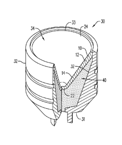
[0018] FIG. 5 is a partial cross-sectional, perspective view of a conical
shaped charge having
a shaped charge liner, according to an embodiment;
100191 FIG. 6 is a flow chart illustrating a method of perforating a
wellbore using a heated
shaped charge, according to an embodiment; and
[0020] FIG. 7 is a flow chart illustrating a further method of perforating
a wellbore using a
heated shaped charge, according to an embodiment.
4
Date Recue/Date Received 2021-08-19
CWCAS-600
100211 Various features, aspects, and advantages of the embodiments will
become more
apparent from the following detailed description, along with the accompanying
figures in which
like numerals represent like components throughout the figures and text. The
various described
features are not necessarily drawn to scale, but are drawn to emphasize
specific features relevant
to some embodiments.
[0022] The headings used herein are for organizational purposes only and
are not meant to
limit the scope of the description or the claims. To facilitate understanding,
reference numerals
have been used, where possible, to designate like elements common to the
figures.
DETAILED DESCRIPTION
[0023] For purpose of illustrating features of the embodiments, embodiments
will now be
introduced and referenced throughout the disclosure. Those skilled in the art
will recognize that
these examples are illustrative and not limiting, and are provided for purely
explanatory
purposes.
[0024] In the illustrative examples and as seen in FIGS. 2A-5, a liner
10/10'/10"/10"
(generally "10") for use in a shaped charge 30 is illustrated. As illustrated
in FIGS. 4 and 5, the
shaped charge 30 may include a case / shell 32 having a wall (or plurality of
walls) 35. The
walls 35 may be configured so that they form the case 32 of a slotted shaped
charge (FIG. 4) or a
conical shaped charge (FIG. 5). The plurality of walls 35 together define a
hollow interior /
cavity 34 within the case 32. The case 32 includes an inner surface 36 and an
outer surface 37.
An explosive load 40 may be positioned within the hollow interior 34 of the
case 32, along at
least a portion of the inner surface 36 of the shaped charge case 32.
According to an aspect, the
liner 10 is disposed adjacent the explosive load 40, so that the explosive
load 40 is disposed
adjacent the plurality of walls 35 of the case 32. The shaped charge 30 has an
open end 33,
through which a jet is eventually directed, and a back end (closed end) 31,
which is typically in
communication with a detonating cord 70 (FIG. 4).
100251 The liner 10 may have a variety of shapes, including conical shaped
(e.g., liner 10') as
shown in FIG. 2A, hemispherical or bowl-shaped (e.g., liner 10") as shown in
FIG. 2B, or
trumpet shaped (e.g., liner 10") as shown in FIG. 2C. To be sure, the liner 10
may have any
desired shape, which may include shapes other than those referenced herein.
Date Recue/Date Received 2021-08-19
CWCAS-600
100261 The shaped charge liner 10 generally has an apex portion 22 and a
perimeter that
forms a skirted portion 24. The shaped charge liner 10 may generally have a
thickness T/T1/T2
(generally "T") ranging from between about 0.5 mm to about 5.0 mm, as measured
along its
length L. As illustrated in FIGS. 2A and 2B, the thickness T is uniform along
the liner length L,
that is, along the apex and skirt portions 22, 24. In an alternative
embodiment and as illustrated
in FIG. 5, the thickness T varies along the liner length L, such as by having
a thickness that is
larger/greater closer to the walls of the case 32 and a thickness that is
decreases or gets thinner
closer to the center of the shaped charge 30 (or apex 22 of the liner).
Further, in one
embodiment, the liner 10 (e.g., liner 10') may extend across the full diameter
of the cavity 50 as
shown in FIGS. 2A-2C. In an alternative embodiment (not shown), the liner
10'/10"/10" may
extend only partially across the diameter of the cavity 34, such that it does
not completely cover
the explosive load 40.
100271 Additionally, the composition of the illustrative liners 10, as seen
for instance in
FIGS. 2A-2C, may be formed as a single layer (as shown). In an alternative
embodiment, the
liner 10' may have multiple layers (not shown). An example of a multiple-
layered liner is
disclosed in U.S. Patent No. 8,156,871.
[0028] According to an aspect, the shaped charge liner 10 generally
includes various
powdered/pulverized metallic and/or non-metallic powdered metals, alloys and
binders. Such
shaped liners are, for instance, described in U.S. Patent No. 3,235,005, U.S.
Patent No.
3,675,575, U.S. Patent No. 5,567,906, U.S. Patent No. 8,075,715, U.S. Patent
No. 8,220,394,
U.S. Patent No. 8,544,563 and German Patent Application Publication No.
DE102005059934.
100291 The shaped charge liner 10 includes a plurality of metal powders 12.
The plurality of
metal powders 12 is compressed to form the shaped charge liner 10. The metal
powders 12 may
include lead, copper, aluminum, nickel, tungsten, titanium, molybdenum,
aluminum-bronze,
manganese-bronze, or any other metal powder or alloys that have a melting
temperature of above
320 C, as would be understood by one of ordinary skill in the art.
100301 The plurality of metal powders 12 includes at least one high purity
level metal 14
having a purity level of at least about 99.5%. As such, the high purity level
metal 14 has less
than about 0.5% of any other type of identifiable metal (i.e., metal
contaminant) within any given
sample.
6
Date Recue/Date Received 2021-08-19
CWCAS-600
100311 FIG. 3 illustrates an exemplary shaped charge 30 including a shaped
charge liner 10
according to embodiments of the present disclosure. According to an aspect,
the shaped charge
liner 10 is heated or thermally softened while positioned in a shaped charge
30 that is disposed in
a wellbore, so that the shaped charge liner 10 has a porosity of less than
about 20 volume %.
The shaped charge liner 10 may be heated so it has a porosity of less than
about 10%. It is
contemplated that the shaped charge liner 10 is thermally softened at a
temperature (T) of up to
about 250 C, alternatively up to about 190 C, prior to detonation of the
shaped charge 30 within
which the liner 10 is disposed. As illustrated in FIG. 3, the inclusion of the
high purity level
metal 14 in the shaped charge liner 10 substantially eliminates or reduces air
pockets (i.e., porous
beads or bubbles) that can form in typical liners when heated, as illustrated
in FIG. 3.
[0032] The at least one high purity level metal 14 is present in an amount
up to about 95% of
a total weight of the plurality of metal powders 12. Various high purity level
metals 14 may be
compressed to form the liner 10. According to an aspect, the high purity level
metal 14 is
selected from the group consisting of copper, tungsten, nickel, titanium,
aluminum, lead,
tantalum and molybdenum. For instance, a copper powder having a hardness of
about 77-99
Vickers (HV) (or 2.5 to 3.0 Mohs) and a tensile strength of 3501ViPa may be
utilized, with or
without another high purity level metal 14. Without being bound by theory, it
is believed that
the hardness of the selected high purity level metal 14 will be reduced when
the shaped charge
liner 10 is heated. According to an aspect, the hardness of the high purity
level metal may be
reduced by an amount up to about 20%.
100331 The melting temperatures of the high purity level metal 14 included
in the shaped
charge liner 10 helps the shaped charge liner 10 (when heated) maintain its
mechanical integrity.
According to an aspect, the high purity level metal 14 has a melting
temperature greater than
about 320 C. Alternatively, the high purity level metal 14 has a melting
temperature greater than
about 600 C, alternatively greater than about 1,050 C, alternatively greater
than about 1,600 C,
alternatively greater than about 3,000 C. According to an aspect, the heated
shaped charge liner
maintains its mechanical integrity (i.e., its original shape) even when
subjected to a
temperature of at least about 250 C.
[0034] The plurality of metal powders 12 may include a first high purity
level metal and a
second high purity level metal. While the first and second high purity level
metals may have
7
Date Recue/Date Received 2021-08-19
CWCAS-600
substantially similar melting temperatures, it is contemplated that the first
high purity level metal
may have a melting temperature that is greater or less than the melting
temperature of the second
high purity level metal. For instance, in some embodiments, the first high
purity level metal may
have a melting temperature between about 320 C to about 1,200 C, and the
second high purity
level metal may have a melting temperature between about 1,400 C to about
3,500 C. In this
configuration, the first high purity level metal will begin to soften, and may
in some
circumstance melt and adhere to the other metals 12 or other high purity level
metals 14 in the
shaped charge liner 10 at a lower temperature than the second high purity
level metal.
100351 According to an aspect, the first high purity level metal may be
present in an amount
of about 5% w/w to about 40% w/w of a total weight of the plurality of metal
powders 12, while
the second high purity level metal may be present in an amount of about 60%
w/w to about 95%
w/w of the total weight of the plurality of metal powders 12. The quantities
of the first and
second high purity level metals in the total weigh to the composition of metal
powders 12 may
be selected at least in part based on the ability of each high purity level
metal's 14 ability to
interact with each other and/or other constituents of the shaped charge liner
10.
100361 The shaped charge liner 10 may include a binder 16. The binder 16
helps to maintain
the shape and stability of the liner 10. According to an aspect, the binder 16
includes a high
melting point polymer resin having a melting temperature greater than about
250 C. The resin
may include a fluoropolymer and/or a rubber. In an embodiment, the high
melting point polymer
resin is VitonTM fluoroelastomer. The binder 16 may include a powdered soft
metal, such as
graphite, that is mixed in with the plurality of metal powders 12. In an
embodiment, the
powdered soft metal is heated (and may be melted) prior to being
combined/mixed with the
plurality of metal powders 12. This helps to provide for adequate dispersion
and coating of the
metal powders 12 within the shaped charge liner 10 and reduces or
substantially eliminates the
amount of dust that may form in the environment, thereby reducing the
likelihood of creating a
health hazard and reducing potential toxicity levels of the liner 10.
[0037] Embodiments of the liners of the present disclosure may be used in a
variety of
shaped charges 20, 30, which incorporate the above-described shaped charge
liners 10. The
shaped charges 20, 30 include a case 32 that has a closed end, an open end 33
opposite the closed
end 31, and a plurality of walls (or wall) 35 extending between the closed and
open ends 31, 33.
8
Date Recue/Date Received 2021-08-19
CWCAS-600
As noted hereinabove, the shaped charge of FIG. 4 is a slot shaped charge 20,
having a closed
end 31 that is substantially planar or flat. In contrast, the shaped charge of
FIG. 5 is a conical
shaped charge having a closed end 31 that has a conical shape. The shaped
charges 20, 30 are
detonated via a detonation cord 70 that is adjacent an area of their close
ends 31 and is in
communication with an explosive load 40 positioned within a cavity (hollow
interior) 34 of the
shaped charge. According to an aspect, the shaped charges 20, 30 may be
encapsulated.
[0038] FIGS. 4-5 illustrate the hollow interior or cavity 34 having an
explosive load 40 is
disposed therein. The explosive load may abut the closed end 31 and may extend
along an inner
surface 36 of the case 32. The explosive load 40 may include at least one of
hexanitrostibane
(HNS), diamino-3,5-dinitropyrazine-1-oxide (LLM-105), pycrlaminodinitropyridin
(PYX), and
triaminotrinitrobenzol (TATB). According to an aspect, the explosive load 40
is a mixture of
pycrlaminodinitropyridin (PYX) and triaminotrinitrobenzol (TATB). As
illustrated in FIG. 4,
the explosive load 40 may include a primary explosive load 42 and a secondary
explosive load
44. The primary explosive load 42 may be adjacent the closed end 31, while the
secondary
explosive load 44 is in a covering relationship with the primary explosive
load 42. The primary
explosive load 42 includes at least one of HNS, LLM-105, PYX, and TATB, while
the secondary
explosive load 44 includes a binder 16 (described in further detail
hereinabove) and at least one
of HNS, LLM-105, PYX, and TATB.
[0039] A shaped charge liner 10 may be disposed adjacent the explosive load
40 (or
secondary explosive load 44), thus retaining the explosive load 40, 44 within
the hollow interior
34 of the case 40. The liner 10, while shown in a conical configuration 10' in
the shaped charges
of FIGS. 4-5, may also be present in a hemispherical configuration 10" as
shown in FIG. 2B. To
be sure, the liners 10 described hereinabove may be utilized in any shaped
charge. The liner 10
may include a plurality of metal powders 12 having at least one high purity
level metal 14.
Therefore, the shaped charge liners 10 of the present disclosure may serve
multiple purposes,
such as, to maintain the explosive load 40 in place until detonation and to
accentuate the
explosive effect on the surrounding geological formation.
[0040] For purposes of convenience, and not limitation, the general
characteristics of the
shaped charge liner 10 are described above with respect to FIGS. 2A-2C and are
not repeated
here. According to an aspect, the liner 10 of the shaped charge 30 includes
the metal powders 12
9
Date Recue/Date Received 2021-08-19
CWCAS-600
subtantially as described hereinabove. For instance, the metal powders 12 may
include at least
one high purity level metal 14 having a purity level of at least about 99.5%.
The plurality of
metal powders 12 and high purity level metal 14 are compressed to form the
shaped charge liner
and after the shaped charge liner 10 is formed, the shaped charge liner 10 is
thermally
softened prior to detonation of the shaped charge 30 into a target. When
heated, the shaped
charge liner 10 has a porosity of less than about 20 volume % and is able to
maintain its
mechanical integrity at a temperature of at least about 250 C.
[0041] The process of allowing heat to be applied to the liners 10 and/or
the shaped charges
20, 30 incorporating the liners 10 according to the present disclosure is
contrary to the
conventional wisdom that shaped charges must be initiated at ambient
temperature immediately
or soon after or deployment in the wellbore. It has surprisingly been found
that the shaped
charge liners 10 described herein do not have to be isolated or protected from
the increased
temperature of the wellbore, because the increase in temperature of the metal
powders and high
purity metal powders actually enhances the performance of the shaped charge
liner 10. By virtue
of the conveyance method for the perforating systems and the downhole
temperature, the liners
10 are pre-conditioned by the exposure to the wellbore's temperature before
the shaped charges
are detonated in the wellbore. The liners 10 (within their respective casing
and/or positioned in a
perforating gun and/or a shaped charge carrier) are pre-conditioned by virtue
of the wellbore
having a temperature that is greater than an initial temperature of the shaped
charge at the ground
surface. The preheating treatment of the liner 10 changes the morphology of
the liner 10 itself so
that an enhanced collapse process of the shaped charge liner and an improved
perforating jet
performance will occur. When the liners 10 are heated in the wellbore, the
metals 12, 14 soften,
which helps to further bind the metals together. The temperature at which the
liner is heated, and
the length of the heat treatment, may be customized according to the types of
powdered metals in
the liners 10.
100421 Embodiments further relate to a method of perforating a wellbore
using a shaped
charge having a shaped charge liner disposed therein, substantially as
described hereinabove. As
illustrated in the flow charts of FIGS. 6-7, at least one shaped charge is
installed 120 into a
shaped charge carrier system, and is positioned 140 into the wellbore. Such
carrier systems may
include a hollow-carrier system having a tube for carrying the shaped charge
or an exposed
Date Recue/Date Received 2021-08-19
CWCAS-600
system having a carrier strip upon which the shaped charge is mounted.
According to an aspect
and as illustrated in FIG. 7, after the shaped charges are positioned into the
carrier system, the
carrier system is thereafter installed/ arranged 130 into a perforating gun
system and the
perforating gun system including the shaped charge carrier is positioned into
the wellbore 142.
100431 The initial ambient temperature of the shaped charge and the shaped
charge liner,
which is typically the initial ambient temperature at a surface (above ground)
of the wellbore, is
less than the temperature of the wellbore. Thus, when positioned in the
wellbore, the shaped
charge and shaped charge liner are both heated from their respective initial
ambient temperatures
to the wellbore temperature. As illustrated in the flow chart of FIG. 6, the
shaped charge is
maintained in a position within the wellbore until the shaped charge and liner
are heated to a
temperature of up to about 250 C before detonation of the shaped charge. In an
embodiment and
as depicted in FIG. 7, the shaped charge liner may be heated for a time period
of up to about 250
hours when positioned in the wellbore. Alternatively, the shaped charge and
liner may be heated
to a temperature of about 190 C for a time period between about 100 hours to
about 250 hours,
prior to the step of detonating the heated shaped charge. According to aspect,
the shaped charge
and shaped charge liner are maintained 165 in the wellbore until the shaped
charge liner reaches
the wellbore temperature.
[0044] When heated in the wellbore, the shaped charge liner is thermally
softened so that it
has a porosity of less than about 20 volume % and maintains its mechanical
integrity at a
temperature of at least about 250 C. The step of heating 160 the shaped charge
and the shaped
charge liner modifies the shaped charge liner so its mechanical properties,
including ductility,
malleability and yield point are improved from the point of high velocity
perforation jet
formation. For instance, at least one of plurality of metals or the high
purity level metal will
have a yield point that is 30%, alternatively 15% to 20%, less than that of
the equivalent metal at
an ambient temperature of about 21 C. In addition, the plurality of metals
and/or the high purity
level metal has a reduction in hardness of at least about 20%.
[0045] Once the shaped charge and shaped charge liner are heated to the
desired temperature,
the heated shaped charge is detonated 180 into the wellbore, and the liner
produces a perforating
jet having a detonation velocity of up to about 8,500 meters/second. The liner
forms a coherent
11
Date Recue/Date Received 2021-08-19
CWCAS-600
and rapidly elongating perforating jet, which reduces particulation or
separation of the
perforation jet upon the detonating 180 of the heated shaped charge into the
wellbore.
[0046] The present invention may be understood further in view of the
following examples,
which are not intended to be limiting in any manner. All of the information
provided represents
approximate values, unless specified otherwise.
EXAMPLE
[0047] Various shaped charge liners may be made according to the
embodiments of the
disclosure. The data presented in the Example shown in Table 1 are based on
the theoretical
properties of the high purity level metals 14 in the metal powders 12. Such
high purity level
metals 14 have purity levels of at least about 99.5%. The shaped charge liner
may include about
5% of a total weight of its composition, other constituents that may aid in
the mixing or
combinability of the metal powders and high purity level metal powders.
Table 1
Temperature Hardness Tensile Strength Elasticity
( C) (Vickers (HV)) (mega Pascal
(giga Pascal
(MP a))
(GPa))
Tungsten Ambient 410 1900-2000 380-410
250 260 1600-1620 360-370
Molybdenum Ambient 260 1300-1400 310-330
250 210 760-800 300-320
Copper Ambient 61-66 350 118-132
250 46-51 250 121
[0048] The high purity level metals 14 presented in Table 1 may include
tungsten,
molybdenum and/or copper. Table 1 presents the hardness, tensile strength, and
modulus of
elasticity for tungsten, molybdenum and copper at an ambient temperature of
about 21 C / 69.8 F
and after each metal is subjected to a temperature of about 250 C / 482 F.
According to an
12
Date Recue/Date Received 2021-08-19
CWCAS-600
aspect, the hardness and tensile strength of the tungsten, molybdenum and
copper metals
decrease when exposed to temperatures up to about 250 C. At 250 C, the
elasticity of the
tungsten, molybdenum and copper metals also slightly decrease. Without being
bound by
theory, it is believed that the heating of the high purity level metals of the
shaped charge liner 10
reduces of the metals' hardness, tensile strength and modulus of elasticity in
a manner that
allows the shaped charge liner 10 to maintain its mechanical integrity and
enhances the
performance of the shaped charge liner 10 when used to perforate steel and
rock formations.
While several combinations of high purity level metals are contemplated, it
has been found that
including tungsten and copper, each having a purity level of about 99.5%.
[0049] The present disclosure, in various embodiments, configurations and
aspects, includes
components, methods, processes, systems and/or apparatus substantially
developed as depicted
and described herein, including various embodiments, sub-combinations, and
subsets thereof.
Those of skill in the art will understand how to make and use the present
disclosure after
understanding the present disclosure. The present disclosure, in various
embodiments,
configurations and aspects, includes providing devices and processes in the
absence of items not
depicted and/or described herein or in various embodiments, configurations, or
aspects hereof,
including in the absence of such items as may have been used in previous
devices or processes,
e.g., for improving performance, achieving ease and/or reducing cost of
implementation.
[0050] The phrases "at least one", "one or more", and "and/or" are open-
ended expressions
that are both conjunctive and disjunctive in operation. For example, each of
the expressions "at
least one of A, B and C", "at least one of A, B, or C", "one or more of A, B,
and C", "one or
more of A, B, or C" and "A, B, and/or C" means A alone, B alone, C alone, A
and B together, A
and C together, B and C together, or A, B and C together.
[0051] In this specification and the claims that follow, reference will be
made to a number of
terms that have the following meanings. The terms "a" (or "an") and "the"
refer to one or more
of that entity, thereby including plural referents unless the context clearly
dictates otherwise. As
such, the terms "a" (or "an"), "one or more" and "at least one" can be used
interchangeably
herein. Furthermore, references to "one embodiment", "some embodiments", "an
embodiment"
and the like are not intended to be interpreted as excluding the existence of
additional
embodiments that also incorporate the recited features. Approximating
language, as used herein
13
Date Recue/Date Received 2021-08-19
CWCAS-600
throughout the specification and claims, may be applied to modify any
quantitative
representation that could permissibly vary without resulting in a change in
the basic function to
which it is related. Accordingly, a value modified by a term such as "about"
is not to be limited
to the precise value specified. In some instances, the approximating language
may correspond to
the precision of an instrument for measuring the value. Terms such as "first,"
"second," "upper,"
"lower- etc. are used to identify one element from another, and unless
otherwise specified are not
meant to refer to a particular order or number of elements.
100521 As used herein, the terms "may" and "may be" indicate a possibility
of an occurrence
within a set of circumstances; a possession of a specified property,
characteristic or function;
and/or qualify another verb by expressing one or more of an ability,
capability, or possibility
associated with the qualified verb. Accordingly, usage of "may" and "may be"
indicates that a
modified term is apparently appropriate, capable, or suitable for an indicated
capacity, function,
or usage, while taking into account that in some circumstances the modified
term may sometimes
not be appropriate, capable, or suitable. For example, in some circumstances
an event or capacity
can be expected, while in other circumstances the event or capacity cannot
occur - this
distinction is captured by the terms "may" and "may be."
100531 As used in the claims, the word "comprises" and its grammatical
variants logically
also subtend and include phrases of varying and differing extent such as for
example, but not
limited thereto, "consisting essentially of' and "consisting of." Where
necessary, ranges have
been supplied, and those ranges are inclusive of all sub-ranges therebetween.
It is to be expected
that variations in these ranges will suggest themselves to a practitioner
having ordinary skill in
the art and, where not already dedicated to the public, the appended claims
should cover those
variations.
[0054] The foregoing discussion of the present disclosure has been
presented for purposes of
illustration and description. The foregoing is not intended to limit the
present disclosure to the
form or forms disclosed herein. In the foregoing Detailed Description for
example, various
features of the present disclosure are grouped together in one or more
embodiments,
configurations, or aspects for the purpose of streamlining the disclosure. The
features of the
embodiments, configurations, or aspects of the present disclosure may be
combined in alternate
embodiments, configurations, or aspects other than those discussed above. This
method of
14
Date Recue/Date Received 2021-08-19
CWCAS-600
disclosure is not to be interpreted as reflecting an intention that the
present disclosure requires
more features than are expressly recited in each claim. Rather, as the
following claims reflect,
the claimed features lie in less than all features of a single foregoing
disclosed embodiment,
configuration, or aspect. Thus, the following claims are hereby incorporated
into this Detailed
Description, with each claim standing on its own as a separate embodiment of
the present
disclosure.
[0055]
Advances in science and technology may make equivalents and substitutions
possible
that are not now contemplated by reason of the imprecision of language; these
variations should
be covered by the appended claims. This written description uses examples to
disclose the
method, machine and computer-readable medium, including the best mode, and
also to enable
any person of ordinary skill in the art to practice these, including making
and using any devices
or systems and performing any incorporated methods. The patentable scope
thereof is defined by
the claims, and may include other examples that occur to those of ordinary
skill in the art. Such
other examples are intended to be within the scope of the claims if they have
structural elements
that do not differ from the literal language of the claims, or if they include
equivalent structural
elements with insubstantial differences from the literal language of the
claims.
Date Recue/Date Received 2021-08-19