Note: Descriptions are shown in the official language in which they were submitted.
¨ 1 ¨
RAILROADHOPPER CAR FITTINGS
AND METHOD OF OPERATION
Field of the Invention
This invention relates to the field of railroad freight cars, and, in
particular to railroad
freight cars such as may employ bottom unloading gates.
Background
There are many kinds of railroad cars for carrying particulate material, be it
sand or
gravel aggregate, plastic pellets, grains, ores, potash, coal or other
granular materials. These
materials are not liquid, yet may in some ways tend to flow in a somewhat
liquid-like manner.
Many of those cars have an upper opening, or accessway of some kind, by which
the particulate
is loaded, and a lower opening, or accessway, or gate, by which the
particulate material exits the
car under the influence of gravity. Clearly, while the inlet opening need not
necessarily have a
movable gate (but may include a cover to discourage contamination of the
lading or exposure of
the lading to the wind), the outlet opening requires a governor of some kind
that is movable
between a closed position for retaining the lading while the lading is being
transporting, and an
open position for releasing the lading at the destination. The terminology
"flow through" or
"flow through railroad car" or "center flow" car, or the like, may sometimes
be used for cars of
this nature where lading is introduced at the top, and flows out at the
bottom.
Consider, for example, a hopper car for transporting aggregate, be it gravel
or sand. The
hopper may have a converging hopper discharge section that has the shape,
generally speaking,
of an inverted four sided, truncated pyramid. At the truncated bottom end,
there may be a
stationary plate and a moving plate, or door. When the moving plate and the
stationary plate are
brought together, the door is closed. The car is filled with lading, and is
hauled to its destination.
At the destination, the gate is opened, and the lading is allowed to escape
from the hopper.
However, it sometimes happens that, for example, the car may move while the
gate is still
obstructed by lading, such that the gate may tend to "plow" the aggregate.
This may not
necessarily lead to the retention of the original geometry of the closure,
and, after a time, the gate
may tend not to close as well as it might originally have done, or as might be
desired. A number
(
of considerations arise from dealing with this kind of issue. First, it may be
helpful to diminish,
or to avoid, the tendency to distort the geometry of the door closure in the
first place. Second, if
CA 3074096 2020-02-27
¨ 2 ¨
the door seal region is prone to damage or abuse, it may be helpful to be able
to replace the parts
most likely to wear or be damaged relatively easily, rather than having to
replace what might
otherwise be considered permanent structure. Third, it is a consideration that
parts employed in
this kind of use may face an abrasive environment, even in normal, non-abusive
operation.
Fourth, particularly if the car is intended to be used with fine aggregates,
such as sand, it may be
desirable to employ a door seal that may tend to be somewhat tolerant of
geometric mismatch, or
creeping tolerances as parts are either damaged or bent out of shape.
Summary of the Invention
In an aspect of the invention, there is a door seal member for a gate of a
hopper of a
railroadcar. The door seal member has at least one fitting by which to secure
the door seal
member to one of (a) a movable closure member; and (b) another closure member
co-operable
with the movable member to form a closure. The door seal member also has a
deflecting
portion, and a land portion for engagement with the other of (a) the other
member; and (b) the
movable member. The deflecting portion is movable in a direction that, when
the fitting is
installed, includes an inward component of displacement relative to the
hopper. The land portion
is connected to the deflecting portion, and is movable to cause the deflecting
portion to be
displaced in that direction of closing of the hopper gate.
In another feature of that aspect of the invention, the door seal member
stores energy
when deflected. In an additional feature, the door seal member is made of a
material having a
rated yield strength of more than 70 ksi. In still another feature, the door
seal member has a
yield strength of greater than 100 ksi. In a further feature, the land and the
deflecting portion are
parts of a monolith. In yet another feature, the door seal member includes a
bent lip located
distant from the fitting, and the land is part of the bent lip. In a still
further feature, the deflecting
portion adjoins the fitting, and the land is formed on a portion of the door
seal member
connected to the deflecting portion distant from the fitting.
In still another feature, there is a door seal assembly that incorporates the
door seal
member of that aspect of the invention. The door seal assembly includes a
second door seal
member. The second door seal member has a proximal portion and a distal
portion. The
proximal portion is attachable to the same one of (a) the movable member; and
(b) the stationary
member, as the first door seal member. The distal portion extends away from
the fitting, and has
a first door seal member contact distant from the fitting. When assembled, the
land of the first
CA 3074096 2020-02-27
¨ 3 ¨
door seal member lies more distant from the fitting than the first door seal
member contact of the
second door seal member. At least a portion of the deflecting portion lies
more proximate to the
fitting than the contact. The first door seal member is movable in engagement
with the contact
when the movable member and the stationary member come together, and the land
is deflected.
In a further feature, the contact includes one of (a) a fulcrum; and (b) a
rocker, against which the
first door seal member acts. In still another feature, when assembled, the
reinforcement is a
backing member, and the land of the seal member is, when installed,
cantilevered beyond the
contact.
In another aspect of the invention, there is a door seal assembly for a
closure of a hopper
discharge section of a railroad hopper car. The discharge section is movable
between a closed
position for retaining lading in the hopper and an open position for
permitting the release of
lading from the hopper. The hopper discharge section includes a first closure
member and a
second closure member. At least one of the first and second closure members is
movable. The
first and second closure members are co-operable. The door seal assembly
includes a first
member and a co-operating second member. The first member and the second
member are
securable to the first closure member of the discharge section of the hopper.
The first member,
when installed, extends from the first closure member, and when installed, the
second member
presents a fulcrum to the first member. The first member has a first portion
that, when installed,
lies between a locus of securement thereof and the fulcrum. The first member,
when installed,
has a second portion cantilevered beyond the fulcrum.
In a feature of that aspect of the invention, the second portion includes a
land that, on
installation, is oriented to face predominantly toward the second closure
member, and is operable
to engage at least a portion of the second closure member when the first and
second closure
members come together. In another feature, in operation, the second portion
engages at least a
portion of the second closure member, and, when so engaged, the second portion
deflects in a
first direction, and the first portion deflects in a reactive direction. In a
further feature, the
reactive direction is a direction that includes a component of direction that
is inwardly with
respect to the hopper. In a still further feature, when the first and second
closure members are in
a closed condition the first portion of the first seal member is exposed to
lading placed in the
hopper, and the first portion of the first seal member is operable under the
influence of lading
bearing thereagainst to cause the second portion of the first seal member to
bear more tightly
against the second closure member.
CA 3074096 2020-02-27
¨ 4 ¨
In still another feature, in operation, the second portion of the first member
of the door
seal assembly deflects in a first direction on engagement of the first and
second closure
members, and the first portion of the first member deflects in a predominantly
opposite direction.
In yet another feature, as installed, the first portion of the first seal
member faces inwardly
toward, and is exposed to, lading borne by the hopper, and the first portion
is operable under the
influence of lading bearing thereagainst to urge the second portion of the
first seal member to
bear more forcefully against the second closure member. In another feature,
the first seal
member has an intermediate portion between the first and second portions
thereof, and, in
operation, the intermediate portion works against the fulcrum as the first and
second closure
members come together. In another further feature, the first seal member has a
locus of contact
against the fulcrum, and has slope continuity at that locus of contact. In
another feature, the first
seal member is operable to carry a bending moment across the fulcrum between
the first and
second portions of the first seal member. In a further feature, the second
portion of the first seal
member includes a bent lip. In still another feature, the fulcrum of the
second member is
cantilevered away from the first closure member of the discharge section.
In still another aspect of the invention, there is a hopper discharge section
of a railroad
hopper car, the discharge section being movable between a closed position for
retaining lading in
the hopper to a open position for permitting release of lading from the
hopper. The hopper
discharge section includes a first closure member and a second closure member.
At least one of
the first and second closure members is movable, and the first and second
closure members are
co-operable. The discharge section also includes a door seal assembly. The
door seal assembly
includes a first member and a co-operating second member. The first member and
the second
member are securable to the first closure member of the discharge section of
the hopper. In the
open condition, the first closure member includes a hopper slope sheet
extension, the hopper
slope sheet extension providing a surface against which lading to be
discharged may slide, the
surface having an angle of inclination. The first member is mountable to
extend from the first
closure member, and the second member is mountable to present a fulcrum to the
first member.
The first member has a first portion that, when installed, lies between the
fulcrum and the
discharge portion of the hopper, and a second portion cantilevered beyond the
fulcrum. In the
open condition, the first member lies in a position that is one of (a)
substantially flush with; and
(b) shy of, the surface of the slope sheet extension.
In another feature of that aspect of the invention, in the closed condition,
at least part of
the first portion of the first member of the seal assembly is located in a
position that is proud of
CA 3074096 2020-02-27
¨ 5
the position of that member when the door is open. In a further feature, in
the closed condition,
at least part of the first portion of the first member of the seal assembly
lies proud of the surface
of the slope sheet.
In another aspect of the invention there is a hopper discharge section that
has substantial
structural reinforcement closely adjacent to the lower margin of the hopper at
which the hopper
discharge section has closure members, of which at least one is movable. In a
feature of that
aspect of the invention, the closure members may be reinforced along their
outwardly facing
sides by substantial structural members. In one feature, those structural
members may form
closed hollow sections. In another feature, the distal margin of a movable
closure member has a
substantial structural reinforcement running therealong. In an additional
feature, the
reinforcement of the door margin may be a channel section. In another feature,
the margin may
include a doubler plate.
In another aspect of the invention, there is a method of operating a discharge
section of a
hopper car. The method includes establishing the car in an empty condition. A
pair of closure
members of the discharge section are brought together, that bringing together
activating a seal
member. The step of activating includes causing a part of the seal member to
deflect inwardly
relative to the hopper. In another feature, the method includes introducing
lading into the hopper
to bear against a portion of the seal member, and, in so bearing, causing the
seal to seat more
tightly.
These and other aspects and features of the invention may be understood with
reference
to the description which follows, and with the aid of the illustrations of a
number of examples.
Brief Description of the Figures
The description is accompanied by a set of illustrative Figures in which:
Figure la is a general arrangement, isometric view of a railroad freight car;
Figure lb is a side view of the railroad freight car of Figure la;
Figure lc is a top view of the railroad freight car of Figure la;
Figure Id is lateral cross-section of the railroad freight car of Figure la,
taken on section
'ld ¨ id' of Figure lb;
CA 3074096 2020-02-27
¨ 6 ¨
Figure le is a longitudinal cross-section of the railroad freight car of
Figure la, taken on
section le ¨ le' of Figure id;
Figure 2a is a plan view of a ridge plate member for the freight car of Figure
la;
Figure 2b is an isometric detail of the ridge plate of Figure 2a, as
installed; and
Figure 2c is an enlarged detail of the railroad freight car of Figure le.
Figure 3a is an enlarged detail of the side view of Figure la, showing a
hopper discharge
assembly with a gate in a closed position;
Figure 3b is a view similar to Figure 3a, but with the gate in an open
condition;
Figure 3c shows a rear perspective view of a movable closure member of the
gate of
Figure 3b under construction with side sill and outboard side sheet removed;
Figure 3d shows an isometric view of the discharge assembly of Figure 3a taken
from
below, outboard, and behind the door crank, with the movable door removed to
reveal the geometry of the hopper discharge throat;
Figure 3e shows an isometric view of the discharge assembly of Figure 3a from
below,
outboard, and behind a fixed hopper discharge slope sheet;
Figure 3f shows a detail of a lip of the discharge assembly of Figure 3a as
seen with the
movable door in an open condition;
Figure 3g shows a similar detail of the lip in a closed condition;
Figure 3h is a detail of a section of the gate of Figure 3a;
Figure 31 is a detail of the door of Figure 3c taken on section '31¨ 3i' of
Figure 3h;
Figure 4a shows an isometric view of an alternate door assembly to that of the
gate of
Figure 3a;
Figure 4b shows a plan view, from in front, of the door assembly of Figure 4a;
Figure 4c shows a top view of the door assembly of Figure 4a;
Figure 4d shows a side view of the door assembly of Figure 4a;
Figure 4e shows a sectional view of the door assembly of Figure 4a taken on
section '4e
¨ 4e' of Figure 4b;
Figure 5a shows a detail of an alternate gate assembly to that of Figure 3h;
Figure 5b shows a detail of a further alternate gate assembly to that of
Figure 3h;
Figure 5c shows still another alternative gate assembly to that of Figure 3h;
Figure 5d shows yet another alternative gate assembly to that of Figure 3h;
Figure 6a shows a scab isometric view of a portion of an alternate embodiment
of gate
assembly to that of Figure 3a;
Figure 6b shows a sectional view of the gate assembly of Figure 6a, analogous
to the
view of Figure 31;
CA 3074096 2020-02-27
¨ 7 ¨
Figure 6c shows a detail of the gate assembly of Figure 6a taken on section
'6c ¨ 6c' of
Figure 6b;
Figure 6d shows a section of an alternate gate assembly to that of Figure 6a;
Figure 7a shows an isometric view of an alternate railroad car to that of
Figure la, the
near side beam of the car being removed to reveal internal detail;
Figure 7b shows a side view of the railroad car of Figure 7a with some
portions showing
hidden details of a door mechanism;
Figure 7c shows a top view of the railroad car of Figure 7a;
Figure 7d shows a transverse cross-sectional view of the railroad car of
Figure 7b taken
on section '7d ¨ 7d'; and
Figure 7e shows a transverse cross-sectional view of the railroad car of
Figure 7b taken
on section '7e ¨ 7e'.
Figure 7f shows a cross-sectional view of the railroad car of Figure 7a with
the side wall
removed, and viewed on an angle downwardly and inwardly toward the center
sill;
Figure 7g shows a perspective view of a gate assembly of the rail car of
Figure 7a,
looking on an upward and inboard angle;
Detailed Description
The description that follows, and the embodiments described therein, are
provided by
way of illustration of an example, or examples, of particular embodiments of
the principles,
aspects or features of the present invention. These examples are provided for
the purposes of
explanation, and not of limitation, of those principles and of the invention.
In the description,
like parts are marked throughout the specification and the drawings with the
same respective
reference numerals. The drawings are not necessarily to scale and in some
instances proportions
may have been exaggerated in order more clearly to depict certain features of
the invention.
The terminology used in this specification is thought to be consistent with
the customary
and ordinary meanings of those terms as they would be understood by a person
of ordinary skill
in the railroad industry in North America. Following from decision of the CAFC
in Phillips v.
AWH Corp., the Applicant expressly excludes all interpretations that are
inconsistent with this
specification, and, in particular, expressly excludes any interpretation of
the claims or the
language used in this specification such as may be made in the USPTO, or in
any other Patent
Office, other than those interpretations for which express support can be
demonstrated in this
CA 3074096 2020-02-27
¨ 8 --
specification or in objective evidence of record in accordance with In re Lee,
(for example,
earlier publications by persons not employed by the USPTO or any other Patent
Office),
demonstrating how the terms are used and understood by persons of ordinary
skill in the art, or
by way of expert evidence of a person or persons of at least 10 years
experience in the railroad
industry in North America or in other former territories of the British Empire
and
Commonwealth.
In terms of general orientation and directional nomenclature, for railroad
cars described
herein the longitudinal direction is defined as being coincident with the
rolling direction of the
railroad car, or railroad car unit, when located on tangent (that is,
straight) track. In the case of a
railroad car having a center sill, the longitudinal direction is parallel to
the center sill, and
parallel to the top chords. Unless otherwise noted, vertical, or upward and
downward, are terms
that use top of rail, TOR, as a datum. In the context of the car as a whole,
the term lateral, or
laterally outboard, or transverse, or transversely outboard refer to a
distance or orientation
relative to the longitudinal centerline of the railroad car, or car unit, or
of the centerline of a
centerplate at a truck center. The term "longitudinally inboard", or
"longitudinally outboard" is
a distance taken relative to a mid-span lateral section of the car, or car
unit. Pitching motion is
angular motion of a railcar unit about a horizontal axis perpendicular to the
longitudinal
direction. Yawing is angular motion about a vertical axis. Roll is angular
motion about the
longitudinal axis. Given that the railroad car described herein may tend to
have both
longitudinal and transverse axes of symmetry, a description of one half of the
car may generally
also be intended to describe the other half as well, allowing for differences
between right hand
and left hand parts. In this description, the abbreviation kspi stands for
thousand of pounds per
square inch. To the extent that this specification or the accompanying
illustrations may refer to
standards of the Association of American Railroads (AAR), such as to AAR plate
sizes, those
references are to be understood as at the earliest date of priority to which
this application is
entitled.
Figure la shows an isometric view of an example of a railroad freight car 20
that is
intended to be representative of a wide range of railroad cars in which the
present invention may
be incorporated. While car 20 may be suitable for a variety of general purpose
uses, it may be
taken as being symbolic of, and in some ways a generic example of, a flow
through car, in which
lading is introduced by gravity flow from above, and removed by gravity
discharge through
gated or valved outlets below. Flow through, or center flow cars may include
open topped
hopper cars, grain cars, plastic pellet cars, potash cars, ore cars, and so
on. In one embodiment
CA 3074096 2020-02-27
¨ 9 ¨
car 20 may be a hopper car such as may be used for the carriage of bulk
commodities in the form
of a granular particulate, be it in the nature of relatively coarse gravel or
fine aggregate in the
nature of fine gravel or sand or various ores or concentrate or coal. Car 20
may be symmetrical
about both its longitudinal and transverse, or lateral, centreline axes.
Consequently, it will be
understood that the car has first and second, left and right hand side beams,
bolsters and so on.
By way of a general overview, car 20 may have a car body 22 that is carried on
trucks 24
for rolling operation along railroad tracks. Car 20 may be a single unit car,
or it may be a multi-
unit car having two or more car body units, where the multiple car body units
may be connected
at an articulated connector, or by draw bars. Car body 22 may have a lading
containment vessel
or shell 26 such as may include an upstanding wall structure 28 which may have
a pair of
opposed first and second end walls 30, 32, that extend cross-wise, and a pair
of first and second
side walls 34,36 that extend lengthwise, the end walls 30,32 and side walls
34, 36 co-operating
to define a generally rectangular form of peripheral wall structure 28. Wall
structure 28 may
include top chords 38 running along the top of the walls, and side sills 40
running fore-and-aft
along lower portions the side sheets of side walls 34, 36. In some instances
car 20 may have
stub center sills at either end, in which case side walls 34, 36 may act as
deep beams, and may
carry vertical loads to main bolsters that extend laterally from the
centerplates. Alternatively, or
in addition to deep side beams, car 20 may include a center sill 42, which may
be a straight-
through center sill, running from one end of the car body to the other. As
seen in Figure id,
center sill 42 has a top flange 41, a bottom flange 43, and webs 39. In the
case of a single, stand
alone car unit, draft gear and releaseable couplers may be mounted at either
end of the center sill.
In a center flow, or flow through car, the upper portion of the car may
typically include means by
which to admit lading under a gravity drop system. Such an intake, or entryway
may be a large
rectangular opening such as bounded by top chords 38, or the car may have one
or more hatches,
whether covered or uncovered.
As shown in Figure lc, the interior of car body 22 may include end slope
sheets 44 and
lateral partitions such as may be identified as intermediate slope sheets 46
that may extend
between the side walls of the car, in a manner such as may tend to divide the
internal space 48 of
car body 22 into two or more sub-compartments, sub-volumes or subspaces
indicated generally
as 50, 52 and 54 in this example, and which may be referred to as hoppers.
Clearly, in some
embodiments there may be one single hopper, in others two hoppers and in
others three, four, or
more hoppers. As may be noted, end sheets 44 may be slope sheets, and internal
partition sheets
46 may also be slope sheets. Not atypically, each pair of fore-and aft opposed
slope sheets, be
CA 3074096 2020-02-27
¨ 10 ¨
they end sheets or internal partitions, may be inclined at equal and opposite
angles, and the
angles of those sheets may be selected to be somewhat steeper than the free
slope angle, or
natural talus slope angle of the lading for which the car is designed, such
that, when the gates are
opened, the lading may tend to flow out, rather than sit at rest.
Car 20 may have relatively large slope sheets, be they 44 or 46, which may
tend to extend
to a height relatively close to top chords 38. That is, taking either the
coupler centerline height
or the center sill cover plate upper surface as a datum, slope sheets 46 may
terminate at a height
that is at least half way to top chord 38, and which may, in some embodiments,
extend more than
2/3, % or 4/5 of that distance, as may be.
Car 20 may include a fitting 60 mounted at the apex where two adjacent slope
sheets 46
meet. Fitting 60 may be termed a partition, or a divider, or a reinforcement.
Although any of
those terms may be used, fitting 60 may be referred to as a ridge plate. As
seen in the plan view
of Figure 2a, ridge plate 60 may include a central portion 62, and end
portions 64, 66. Central
portion 62 may be formed of a flat bar, which may be of substantial thickness,
be it 1/2 inch, 5/8
inch, % inch, or some different dimension.
It may be that ridge plate 60 is formed of a single monolithic part, cut to
shape.
Alternatively, the components of ridge plate 60, namely items 62, 64 and 66,
may each be
individually cut to shape, e.g., from a sheet or plate, and then assembledõ
typically by being butt
welded together to yield the form shown in Figure 2a. On assembly, or sub-
assembly, slope
sheets 46 may be mounted together in a jig, along with ridge plate 60, and a
laterally extending
cross-gusset 70. Rather than having a single large fillet at the adjoining
margins 72, 74 of slope
sheets 46, (as would occur absent fitting 60) fillets may be formed on either
side of ridge plate
60, as indicated at 76, 78. Ridge plate 60 is positioned such that a portion
thereof, identified as
upper portion 80 extends upwardly proud of the junction of slope sheets 46,
or, indeed, what
would be the location of the junction of those sheets but for the
interposition of ridge plate 60.
Ridge plate 60 may also include a lower portion 82, that extends lower than
this junction. The
width of ridge plate 60 (i.e., in the vertical direction) may permit it to
function, inter alia, as a
backing bar for welding, that presents a significant dimensional tolerance for
fit up on either
side. Furthermore, the upper margin 84 of upper portion 80 may provide a
solid, hard edge of
relatively thick material that may tend to resist abuse perhaps somewhat
better than might a more
conventional apex.
CA 3074096 2020-02-27
¨ 11 ¨
Ridge plate 60 may, in one embodiment, have a constant cross-section, such as
that of
portion 62, at all locations across the car, from side sheet to side sheet.
Alternatively, end
portions 64, 66 may have a generally triangular shape and may, along its upper
margin have an
arcuate or angularly inclined profile, and may extend generally upwardly in
the outboard
direction. This profile may be such that ridge plate 60 has an outboard margin
85 that mates
with, and extends upwardly against, side sheet 35, in a manner to form a stem
such as may tend
locally to discourage lateral deflection of top chord 38. In one embodiment,
at least a portion 86
of margin 85 may extend to a height that lies upwardly of the lower margin of
top chord 38. Top
chord 38 may be an angle or channel, or hollow structural section, such as a
square or
rectangular steel tube, and side sheet 35 may overlap the inner face of top
chord 38.
It may also be noted that a triangular tube 68 is formed by the co-operation
of slope
sheets 46 and the horizontal plate defined by cross-gusset 70. This tube may
extend from side
sheet to side sheet, and may be welded thereto. End potions 64, 66, working in
conjunction with
side sheets 35, may tend to form a stem of a T-section to which side sheet 35
forms the cross-
piece or flange, by which the stiffening influence of the triangular tube is
extended to the top
chord. Expressed somewhat differently yet again, the combination of the tube
and the two stems
may tend to function in a mamier akin to a spring that may resist lateral
deflection of the top
chords. In terms of vertical scale, the central portion 62 of ridge plate
fitting 60 may be
relatively small as compared to the lineal run or vertical rise of either
slope sheet 46 or end slope
sheet 44. For example, it may be less than 20 % of either of those distances,
and may be of
lesser magnitude than the depth of the top chord or half the depth of the
center sill. In other
comparative terms, the depth of the central portion 62 of ridge plate fitting
60 may be less that
the depth of tube 68 from cross-gusset 70 to the apex at the intersection of
the planes of the
upper surfaces of the adjacent slope sheets. The height of cross-gusset 70
may, itself, be more
than half way to the height of the top chord upper flange, as measured from
with the coupler
centerline or from the center sill top cover plate upper surface. In absolute
terms, the central
portion of ridge plate fitting 60 may be less than 1 ft, and may, in one
embodiment be less than 6
inches in depth.
Slope sheets 44 and 46 may have relatively large spans. So that the spans
might not be
unsupported, car 20 may include intermediate shear web panels 45 (associated
with end slope
sheets 44) and 47 (associated with intermediate slope sheets 46) that may
extend amidst the
otherwise unsupported span and provide a link to center sill 42. Pairs of
panels 45 and 47 may
CA 3074096 2020-02-27
¨ 12 ¨
be laterally outwardly splayed with respect to one another as seen, for
example, in Figure id.
Panels 45 and 47 may include lightening apertures as indicated at 49 and 51.
The lower regions of car body 22 may include gate or discharge assemblies 90,
for the
various hoppers, however many there may be, by which one or more members that
are movable
between closed and open positions may be used as a flow control to govern the
egress of lading
from that hopper.
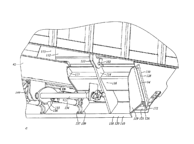
Referring to Figure 3a, the discharge assemblies 90 may include the lower
portion of, or
a continuation of, one or both of the fore-and-aft slope sheets defining the
fore and aft walls of
that hopper. For example, hopper 50 (it being chosen arbitrarily, and
generically) may include a
first fore-and-aft hopper slope sheet extension 92, mounted to one slope
sheet, e.g., item 44, and
a second fore-and-aft slope sheet extension 94 mounted to an opposed slope
sheet, e.g., be it item
46.
Discharge assemblies 90 may also include a pair of opposed side sheet members,
96, 98.
Side sheet members 96, 98 may be steel plates, and may be positioned to co-
operate with slope
sheet extension 92 to define a converging, or funnel-like passageway, or
conduit, leading to a
throat, or opening, indicated generally as 100, at which an exit, or port, or
gate, however it may
be termed, is defined. In particular, the sides of the periphery of discharge
opening 100 may be
defined by the margins 106 of side sheet members 96 and 98 that angle upwardly
and away from
slope sheet extension 92. The bottom edge, or sill, of the discharge opening
may be defined by
the lowest margin or extremity of slope sheet extension 92, or such fittings
or assemblies as may
be mounted thereto, as may be described hereinbelow. First slope sheet
extension 92 may be a
panel that is rigidly fixed relative to the first slope sheet, and may be made
from a metal, such as
a steel, that may serve as a wear plate, and which may be hardened or alloyed
for such a purpose.
Slope sheet extension 92 may be reinforced along its lower lateral margin by a
lip stiffening
member 88, which may be a U-pressing, or channel, mounted to the outside face
of extension 92
and forming a hollow section therewith, capped by the wings, or tabs 56 of
side sheet members
96, 98.
Slope sheet extension 94 may be a movable slope sheet extension, and maybe, or
may be
part of, a moveable closure member or closure assembly that is mounted to move
between a
closed position (Figure 3a) obstructing flow through throat 100, and an open
position (Figure
3b) in which flow through throat 100 is less obstructed, such that lading may
be discharged. To
that end, slope sheet extension 94 may be connected to the rest of body 22 at
a hinged or pivoted
CA 3074096 2020-02-27
¨ 13 ¨
member, such as a pivot pin or hinge 102, such as may tend to constrain slope
sheet extension 94
to a single degree of motion relative to opening 100, which, in one
embodiment, may be angular
displacement (i.e., rocking or pivoting motion, about an axis, such as the
axis of hinge 102). By
virtue of its motion, slope sheet extension 94 may be considered to be, or to
be part of, a door or
door assembly, or closure, or closure assembly such as may be referred to
generally as 110. A
shroud 104, which may be flexible, may be mounted along the nether edge of the
slope sheet, be
it 44 or 46, and may have a depending margin 105 that engages the upper
laterally extending
margin of extension 94. Shroud 104 may be biased to maintain contact with
extension 94 and
may be mounted to the underside of sheet 44 or 46.
Where car 20 includes a straight through center sill, such as item 42, rather
than having a
single full width hopper discharge assembly 90, such as might tend to be
centered on the
longitudinal centerline of the car, there may be two such discharge assemblies
90, one mounted
to either side of center sill 42, in car 20. In this latter case, the center
sill may tend to be
protected from abrasion or other damage by one or more shrouds 108. Shroud 108
may, in cross-
section, have the form of an inverted V, whose arms may extend on an incline
upwardly from the
upper, laterally inboard margin of inboard side sheet members 96, to meet at
an apex above
center sill 42 along the centerline of the car.
Considering now door assembly 110, as a preliminary matter it may be noted
that the
lower laterally running margins of the slope sheets, be they items 44 or 46,
may be reinforced by
a lateral margin reinforcement member, 112. Member 112 may be such as to have,
or to co-
operate with the respective slope sheet to yield, a closed periphery hollow
section, i.e., a hollow
tube, that may be capped inboard by a web 113, and outboard by side sheet 115
(Figure 3e) of
the hopper (whichever it may be), thus providing a shear web to discourage
deformation of the
tube section. The tube so created may tend to add an aspect of robustness to
the structure, and
may tend to discourage dimensional distortion along the margin, and hence
along the hinge and
along the slope sheet extensions, as may be. In one embodiment, member 112 may
be a
generally channel shaped U-pressing, which may have somewhat splayed legs, the
toes of the
legs being mounted against, and welded to, the slope sheet, and the back
standing outwardly
therefrom.
Door assembly 110 may include motion accommodating, or motion permitting,
fittings,
such as hinge 102. Hinge 102 may be received in a pivoting arm member, 114
which, itself may
nest between webs 111 defining a clevis. Arm member 114 as may run along the
back of the
CA 3074096 2020-02-27
¨ 14 ¨
door pan sheet, or wing, defined by extension 94. Arm member 114 may extend
generally
radially away from hinge 102 toward the distal margin of extension 94, and may
be a
substantially planar member lying in a plane perpendicular to the axis of
hinge 102. Given that
hopper doors seem to be prone to abuse in service, extension sheet 94 may have
a laterally
extending reinforcement 116 that may run across the back of extension 94, not
overly far from
hinge 102. Reinforcement 116 may have, or may co-operate with extension 94 to
define, a
hollow structural section, which may include either internal shear webs, (one
of which may be
defined by the body of pivoting arm member 114 itself), or end caps defined by
the inboard and
outboard stiffeners 117, 119 of door assembly 110. Reinforcement 116 may have
the general
form of a channel having toes welded to extension 94, and may be a U-pressing.
Door assembly
110 may be reinforced along the distal edge of the door by yet another lateral
reinforcement
member 118. In one embodiment, member 118 may have the form of a channel
section 120,
which may be mounted with one leg welded flat to the back of sheet 94, quite
near the distal
margin of extension 94. Once again, member 118 may provide a certain
robustness of structure,
such as may tend to discourage distortion of the distal margin of sheet 94
when the car moves
with the door acting as something of an unintentional plow while the discharge
section is still
obstructed by the lading being discharged. In addition, either extension 94
may be thicker along
its distal margin, or a further backing or reinforcement member such as a
doubler 121 may be
located between channel section 120 and extension 94. Reinforcement member 118
may extend
not only across the back of door assembly 110, but also across the back of the
adjacent opposite
handed door assembly 110 mounted on the opposite side of the car such that the
two door
assemblies may be yoked together. Door assembly 110 may also include end webs
or end
gussets, namely stiffeners 117, 119, such as may tend to run predominantly
radially along the
back of extension 94 near to the predominantly radially extending margins of
extension 94.
The front or forward facing surface 124, or face of the panel or door sheet,
or pan defined
by extension 94, may, in one context, be defined in terms of facing toward the
interior of the
volume of the hopper, or in a direction facing toward the lading, or toward
the opposed members
of the hopper discharge assembly in either the closed or the open position.
The back or rear face
126 of the door sheet will not tend to face inwardly with respect to the
hopper, the lading or the
discharge assembly under either the open or closed positions of the door. The
front, or upward,
or inward facing surface 124, however, will tend, in general, to face inwardly
toward the lading.
Door assembly 110 may include upstanding lips, or cheeks, or legs, such as
side wall members
128, that stand proud of the inwardly facing surface of the door. The root of
members 128 may
lie directly over the mating webs of the gussets, namely items 117 and 119
(Figure 3e). When the
CA 3074096 2020-02-27
¨ 15 ¨
mating moving and stationary portions of the discharge assembly come together,
members 128
may tend to seat against the opposed lateral cheek, rim or lip, such as may be
defined by a
backing plate, or bar 130 welded to one or the other of items 96, 98 (Figures
3b, 3g, 3i).
The door assembly 110 is driveable between open and closed conditions by an
operating
mechanism, indicated generally as 140. This mechanism may include a driven
shaft 134, a crank
arm 136, and a link arm 138. The outer end of shaft 134 is supported by
support arm 133
depending from cross member 112 of body 22. Link arm 138 may be of adjustable
length,
typically a device having a left hand thread at one end, and a right hand
thread at the other, such
that turning the barrel adjusts the length, at which point the device is
secured, whether with
locknuts, or wired locknuts, or by some other means. In any case, the link arm
is adjustable on
fit up when the door is installed and assembled. Door arm crank 136 may
include an over-center
stop 135, such that when crank arm 136 and link arm 138 are moved to an over-
center condition,
(e.g., when the door is in a closed condition), and lading bears against the
door, the crank and
link may tend to be forced to a secured, closed position, rather than tending
to creep to an open
position such as may have a greater tendency to permit lading to leak. As seen
in Figure 3d, the
entire arm assembly may be driven by a motive apparatus, which may include a
pneumatic ram
142, connected to a crank arm, clevis or double crank arm, 144. As also seen
in Figure 3d,
bottom flange 43 of center sill 42 splits and has a widened portion indicated
at 37. An
accommodation, or pocket, 33, within center sill 42 is seen between the split
halves of bottom
flange 43 in widened portion 37. As seen in Figure 3d, pneumatic ram 142 is
mounted in pocket
33, while the arm assembly is mounted under center sill 42.
In one embodiment, the movable door assemblies 110 of adjacent discharge
sections on
either side of center sill 42 may be connected to a common shaft 134 driven by
the motive
apparatus. Double crank arm 144 may be rigidly mounted centrally to shaft 134
and may
function as an input lever to provide torque thereto. The output levers,
namely crank arms 136,
may also be rigidly mounted to shaft 134. The ends of connecting rods or links
arms 138 are
mounted in a clevis formed in two webs 137, 139, that embrace the inboard rear
face
reinforcement, item 117, of the door panel namely extension 94 at its junction
with the distal
reinforcement channel section 120.
A seal or seal assembly 150 may be mounted along the distal edge of slope
sheet
extension 92. Seal assembly 150 may include a door seal member 152 having one
or more
fittings, such as through holes, by which member 152 may be attached to slope
sheet extension
92. The uppermost, or proximal margin of member 152 may be trapped between
extension 92
and another member, which may be a reinforcement or backing, such as a backing
plate 154, that
may run laterally across the back of extension 92, near the lower margin of
extension 92.
CA 3074096 2020-02-27
¨ 16 ¨
Fasteners 156, which may be threaded fasteners, or fasteners that involve
plastic deformation or
clinching, such as HuckTM bolts or rivets, may be used to secure the backing
or reinforcement,
and hence seal member 152, in. place. The fasteners may be pan head fasteners.
In general it
may be that the design may seek to minimize the extent to which downstream
features stand
proud of the plane P of extension 92, (i.e., the plane of the discharge slope)
such as might
otherwise present loci at which particulate may catch and build up rather than
slide.
Backing plate 154 may overlap the lower margin of extension 92, such that a
proximal
portion 157 backs extension 92, and a distal portion 158 extends in an
inclined manner generally
downward, predominantly in the direction of the slope of extension 92.
Distal portion 158 may have (when installed) a lowermost margin 160, which may
also provide a
contact for the back, or downward side, of seal member 152.
Seal member 152 may include a first margin, which may be called a proximal
margin
162, that is clamped by backing plate 154 to extension 92. Seal member 152 may
also include a
first portion 164, which may be termed a proximal portion, that overlies
backing plate 154. Seal
member 152 may include a second portion, 166, that may be a distal portion,
that may be
cantilevered beyond lowermost margin 160 of backing plate 154. Second portion
166 may
include a land, 170, against which the opposing closure member may bear when
the moving and
stationary parts of the door are brought together. In one embodiment, it may
be the most distal,
laterally extending margin or lip 172 of door assembly 110 that contacts, and
deflects, land 170.
It may be that land 170 is a surface of second portion 166 that faces
generally toward lip 172,
and the distal margin 174 of second portion 166 may be bent, as at 176 to
orient land 170 in such
a manner as may tend to present that surface in an orientation generally
perpendicular, or more
nearly perpendicular than otherwise, to the motion of lip 172 on closing. Seal
member 152 may
be thought of as having a first face 178 that faces generally toward, or into
the volume of the
hopper space 180, and, when the car is loaded, toward the lading. It may be
that most of this
surface faces at a somewhat upwardly angle. Seal member 152 may also have
another surface,
182, which may be termed the back or downward facing surface, which may, in
the undeflected
condition, tend to lie against backing plate 154.
Seal member 152 may be considered to be a spring, i.e., an elastic energy
storage device.
When the opposed interface surface, or contact, e.g., lip 172, engages land
170, that motion may
tend to urge land 170 to the deflected position 8174 shown in phantom lines in
Figure 3h. In so
doing, seal member 152 is flexed against the contact point, or fulcrum,
defined by the lowermost
CA 3074096 2020-02-27
¨ 17 ¨
margin 160 of backing plate 154. The bending moment tends to flex first
portion 164 away from
backing plate 154 as suggested by the reactive displacement identified by
6164. When the door
opens again, seal member 152 may tend to release, and to move back to its
former undeflected
position. When the door assembly is once more in the closed condition, seal
member 152 may
again flex as discussed above. When lading is retained in car 20, in whichever
hopper may be
employed, the weight of the lading may tend to bear against first portion 164,
and may tend to
urge first portion 164 toward, or against, backing plate 154. In doing this,
land 170 may tend to
be urged all the more tightly against lip 172, which may, in turn, tend to
discourage the leakage
of lading. As a matter of terminology, a fulcrum may tend to approximate a
point or line contact
about which the lever arm pivots or rotates. To the extent that the fulcrum is
not a perfectly
sharp point, but may have a radius, there may also be rocking action, to a
greater or lesser extent,
and, for a sufficiently large radius, the motion may be considered that of a
rocker. In either case,
the relationship is of a lever that, if pushed down on one side, rises on the
other.
Side blocks 184 (Figures 3f and 3g) may be mounted at the lateral edges of
first portion
164 to discourage sideways migration of lading past the side edges of seal
member 152. Side
blocks 184 may include an extending finger 186 that opposes and may abut the
lower margin of
extension 94 when the moving and stationary portions of the assembly come
together. In a
further optional feature, it may be helpful when the lading includes
magnetizable materials, be it
iron ore or concentrate, to employ a magnet such as magnet 188, near the door
closure as seen in
Figure 3g. Magnet 188 may be a rare earth magnet, and may be mounted close to,
or at, the
corner of the opening, i.e., adjacent to the lateral end of the seal member,
when the side and
transverse edges of the door may meet, and where there may be a small gap. The
presence of
magnet 188 may tend to attract iron filings (or filings of such other lading
material as may be) to
obstruct such gap, or crack, or opening in the vicinity of magnet 188.
Seal member 152, or analogous structure, could be mounted on the moving door
member,
and the stationary door member could have a lip analogous to lip 172; or
alternatively, seal
members could be placed on both sides of the closure interface, although this
might perhaps
seem redundant in some instances. In each of these alternatives, there is
relative motion of the
moving and stationary portions of the door assembly between open and closed
conditions, such
that discharge assembly 90 governs the retention and outflow of lading. At the
coming together
of the door components, mutual engagement of the one with the other causes
elastic deflection of
an energy storage device. The elastic deflection, may involve flexing a seal
member in the
manner of flexing a beam, and may include flexing the beam member over a
contact, or rocker,
CA 3074096 2020-02-27
¨ 18 ¨
or fulcrum. Inasmuch as the flexing may be toward, or may include a component
of
displacement toward, the lading, or the space that the lading would normally
occupy, the
introduction of lading into the lading containment structure may tend to
result in lading bearing
against the flexed seal member, with the tendency to cause that seal member to
seal more tightly
than otherwise.
In the alternative embodiment of Figures 4a ¨ 4e, the movable closure member,
or door
assembly of the apparatus of Figures 3a ¨ 3h is replaced by a movable door
assembly 190. Door
assembly 190 may include a first, or front sheet, 192, central, or inboard,
and outboard back
panels 194, 196, a proximal or back closing member, or members 195 or 197 and
a distal or front
closing member 198, those items being mounted in co-operative fashion to form
a closed box
section. The box section may be closed at its laterally outboard ends by webs
such as may be in
the nature of closure plates 200. Door assembly 190 may have a central rebate
or
accommodation 202 such as may seat about the center sill. The inboard portions
of the box
section are closed about the periphery of accommodation 202 by webs such as
may be identified
as side members or cheek plates 204, 206 that extend predominantly radially
with respect to the
axis or rotation of the door, and a closure plate 208 that extends
predominantly longitudinally,
and co-operates therewith to form a generally U-shaped peripheral wall. Left
and right hand
pairs of driven lug gussets 210, 212 are mounted to either side of
accommodation 202 and
closure plate 208, and extend from respective cheek plates 204, 206 to front
sheet 192 and front
closing member 198. Door assembly 190 may also include hinge lugs 214, 216 and
lug
extension webs 218, 220 that extend radially from lugs 214,216 and provide a
shear web linkage
between front sheet 192, back panels 194, 196, front closing member 198, and,
in co-operation
with lug 214 or 216 as may be, with back closing members 195 or 197. On
assembly, side
closing members such as items 128 and 130 may be located on trial
installation, and welded in
place according to the actual fit-up of the door.
Front or distal closing member 198 may have the form of a bent plate that has
a first
margin abutting the back of front sheet 192 at a location near or adjacent to
the distal margin 222
of front sheet 192. In one embodiment, it may meet just shy of the lip, both
on the distal edge
and laterally. Closing member 198 may also include a first portion 224 such as
may tend to be
generally perpendicular to, and such as may abut, member 198, and an
extension, or skirt 226
such as may extend away from member 198. Skirt 226 may extend rearwardly at an
angle, and
may run along the conforming margins of double shear lug gussets 210, 212 and
hinge lug
gussets extension webs 218, 220. Skirt 226 may tend to be of greatest depth in
the region of
CA 3074096 2020-02-27
¨ 19 ¨
double shear lug gussets 210, 212, and may diminish in size toward the
laterally outboard
extremities thereof, as on a taper. This may tend to form a reinforced channel
along the bottom,
or distal edge of the door, and hence to provide a means for spreading loads
along that edge, and
for transmitting rotational torque received at lug bores 228 all along the
distal edge of the door.
This embodiment may tend to provide a relatively simple, and yet quite robust
structure such as
may tend to resist harsh or abusive service.
Figure 5a shows an alternate embodiment of a gate or door assembly having a
seal
assembly, indicated generally as 230. It may be taken that the basic structure
of the railroad car
and the discharge sections is as described above and that seal assembly 230 is
similar to seal
assembly 150 as described above. A seal member 152 is mounted between a
backing member
234 and the distal margin 232 of the slope sheet extension 92. In this case,
backing member 234
includes a dog-leg portion 236 that stands outwardly (i.e., generally
downwardly) of the plane
`P' of the first portion 164 of seal member 162. Dog-leg portion 236
terminates in a return leg
238 having a formed curl, or cusp, or lip, 240, that defines the rocking point
or fulcrum against
which seal member 152 works when engaged by lip 172. When assembled there may
be a gap,
6236 between seal member 152 and dog-leg portion 236.
It may be noted that seal member 152 may have its upper margin clamped between
the
slope sheet extension and backing member (be it 154 or 234) in such as way as
to have a built-in
end condition at their upper margins. That is, not only is the displacement of
the upper margin
fixed at zero, but the slope is also fixed at the angle at which the margin is
clamped, and
deflection implies bending and a bending moment (as opposed to a pin-jointed
or hinged
connection that can rotate freely). If seal member 152 is thought of as being
a beam, which may
have a bent end, the major portion of the beam may lie in a plane, when
undeflected.
Alternatively, a plane J may be constructed along the rearward face of the
seal member across
the point of tangency against the fulcrum or rocker of the distal margin of
the backing plate. The
closing action of the gate may tend to yield contact that has a component of
motion that may
tend to be perpendicular to that plane, and a component of motion that may
tend to be parallel to
that plane. The perpendicular component will tend to work on a moment arm, L,
relative to the
pivot or fulcrum point, to flex seal member 152. To the extent that the end of
the beam is bent,
and the contact occurs out of this plane, the eccentricity of the component
parallel to the plane
may tend to enhance the tendency of the member to flex, rather as an
eccentrically applied load
may have an enhanced tendency to urge a column to buckle. This eccentricity,
from the plane to
the center of contact, is notionally indicated as E.
CA 3074096 2020-02-27
¨ 20 ¨
Another alternate embodiment of seal arrangement is shown in Figure 5b. Again,
this
embodiment is substantially similar to that of Figure 5a, except as noted. In
this instance, the
slope sheet extension of the movable door member, indicated as 244,
incorporates a distal edge
lip 246 that is bent in the generally forward (i.e., forward in terms of the
direction of motion
when the door is closing), or upward direction. The mating, co-operating
flexible seal member
248 has a tip 250, that is caught by, and deflected by, engagement of lip 246.
This may tend to
urge seal member 248 to deflect upwardly, away from backing member 252.
Introduction of
lading may tend to cause seal member 248 to push more strongly toward backing
member 252,
and, to the extent that door member 244 is in a fixed and locked position, the
mutual engagement
of parts may tend to become tighter. In this instance, seal member 248 may not
have a bent
distal lip, but may have a straight profile.
Still another embodiment is shown in Figure Sc, the moving door assembly 260
may be
substantially the same as door assembly 110. A flexible seal member 262 is
mounted to a
backing bar 264 that is spaced therefrom by a washer, or spacer or shim 266.
The distal end of
backing bar 264 may be bent as indicated at 268 to define a fulcrum 270 at the
most distant tip.
The included angle between the door sheet 272 and the tangent plane of
undeflected seal
member 262 at the point of contact is less than 90 degrees, such that the tip
274 of door sheet
272 may tend to ride against, and progressively deflect, the cantilevered end
portion 276 of seal
member 262. As before, introduction of lading into the hopper may tend to
cause pressure to be
exerted by the lading on seal member 262 between fulcrum 270 and shim 266,
such that it may
tend to deflect into the gap region 'G' identified between seal member 262 and
backing bar 264.
In the similar embodiment of Figure 5d, the seal member 282 is pre-bent on a
curve to
give a pre-existing gap 284 between the proximal portion of the seal member
and the backing
bar. The curve is such that at the point of engagement 286 between the distal
edge 288 of the
moving door sheet and seal member 282 there is a non-perpendicular slope, such
that the
resultant wedging action as the door is closed may tend to cause greater
deflection in seal
member 282, increasing its curvature, widening gap 'G', and forcing the distal
extremity of seal
member 282 in the opposite direction.
Figure 6a shows another embodiment of seal assembly, indicated generally as
300. In
this embodiment, the first member of the seal assembly may be an extension 302
of the slope
sheet, or pan sheet of either the moving or stationary portion of the door,
which may be an added
CA 3074096 2020-02-27
¨ 21 ¨
plate or an extended margin formed as an integral part of the door pan, or
extension sheet. When
formed integrally, the need for fasteners such as item 156 identified above,
may be obviated. In
any case, sheet 92 (or 94, as may be) may have an extended margin, as at 304,
which may be
integrally formed, and which may include a bent distal portion 306, defining a
land 308 for
engaging the other closure member when the opposed closure members of the gate
are brought
together. Assembly 300 may also include a second member in the form of a
backing element, or
backing member or reinforcement fence assembly 310, that may include an array
of arms, or
legs, or braces, however they may be termed, identified as 312, which may be
in the form of
tapered posts having a base or root leg fixed to the closure member lateral
reinforcement or tube,
namely item 88. The distal portion of the legs may support, and may have a
niche, notch, slot,
relief or rebate defining an accommodation in which a laterally extending
member, such as a
reinforcement or backing bar 314 is seated. Backing bar 314 may extend across
the full width of
the closure member, from side plate to side plate. Backing bar 314 may be
fixed in place on
braces 312 by such means as mechanical fasteners or welding. In this
embodiment, a portion of
extended margin 304, lying down-slope from reinforcement tube 88, extending
over a distance 1,
is not permanently secured to either the forward faces of the legs 312 of
fence assembly 310, or
backing bar 314, but rather may be free to flex. As such, when the distal
portion of the seal
member is engaged, by pushing on land 308, the inward lower edge of backing
bar 314 may act
as a fulcrum, and the inner or proximal portion 318 of the first seal member
(i.e., the portion of
the margin extension lying between fulcrum edge 316 and reinforcement tube 88,
may tend to be
permitted to flex in a direction that is predominantly inwardly relative to
the hopper more
generally. As above, when engaged, and the gate is in a closed position, the
presence of lading
bearing against the flexed portion 318, may tend to urge the distal portion,
308 to bear all the
more tightly against the opposing closure member, such as may be.
As shown in Figure 6c, the embodiment of Figure 6a may also include a mating
door
member 320 that has a bent lip, as indicated at 322. This bent lip may be of a
similar flexural
nature to the opposing bent lip 316, and, on engagement, either or both may
deflect, and form a
spring loaded seal. It may also be that the side plates 324 of the chute may
be provided with
internal stops, or abutments, identified in this instance as seal bars 326,
against which the lateral
margins of the gate door sheet 330 may engage, and whose ends may oppose, or
abut, extension
304 on closure. Those seal bars 326 may be fit up on assembly, and welded in
place from
outside by means of pre-formed welding access slots 332.
The seal member, be it item 152, 262 or 302, transmits a bending moment across
the
CA 3074096 2020-02-27
¨ 22 ¨
fulcrum (whether it be called a fulcrum, pivot, rocker, or some other term).
Although seal
member 152,262 or 304 may have a bend at the fulcrum, more generally it may
tend to be a flat,
or straight, beam, and so will also have slope continuity at the fulcrum. Thus
the bending
moment that deflects the distal portion of the seal member, will also cause
flexure in the
proximal portion. Assuming a beam, and imposing a Cartesian frame of reference
in which the
x-axis lies in the plane of the undeflected beam, and the y-axis is
perpendicular to the x-axis, and
assuming deflections that are relatively small as compared to the length of
the beam, deflections
of the distal portion that have a component that may be taken as being
substantially
perpendicular to the initial, undeflected profile of the beam, may be
considered to be deflections
in the ¨y direction. When this occurs, the proximal portion of the beam may
tend to flex in the
opposite, or +y direction. In this sense, it may be said that deflection of
the distal portion in one
direction yields a flexing of the proximal portion in a reactive, or in some
sense, opposite,
direction. This may also be expressed in somewhat different terms, taking
plane P as a frame of
reference. In the open position, that portion of the seal member lying inboard
of the lip may tend
to lie more or less flat flush with, or perhaps somewhat shy of, plane P of
the slope sheet along
which the lading may slide during discharge. More generally, all of the seal
assembly my lie
flush or shy of this plane. However, when the closure members mutually engage,
the proximal
portion (between the fulcrum and the proximal edge or part of the seal member
attached to the
slope sheet extension, be it 92 or 94), will tend to flex to a position that
is either less shy of the
former, un-flexed position relative to plane P, or proud of plane P.
Similarly, when lading is
then added, and bears upon the flexed portion, it will tend to want to sit
down, less proud than in
its flexed, but unladed, position.
The seal member, be it item 152, 262 or 304, may be exposed to an abrasive
service
environment. As such, it may be made of a relatively abrasion resistant
material, such as a high
yield stress steel. It may be a stainless steel. In various embodiments, the
yield stress may be as
great or greater than 50 kpsi, 70 kpsi or 100 kpsi. In another embodiment it
may be as great or
greater than 130 kpsi. In another embodiment, it may be as great or greater
than 150 kpsi. It
may also be noted that the seal member, be it 152, 262, or 304, may be a
replaceable without the
need for employing welding or cutting torches. That is, when the part is no
longer serviceable,
either due to wear or damage, the fasteners can be removed, a new part
inserted, new fasteners
installed, and then the car may be operated as before.
Figure 7a shows an isometric view of an alternate example of a railroad
freight car 420
that is intended to be representative of a wide range of railroad cars in
which the present
CA 3074096 2020-02-27
¨ 23 ¨=
invention may be incorporated. In this view the near side beam is removed to
permit internal
features of the car to be seen more easily While car 420 may be suitable for a
variety of general
purpose uses, it may be taken as being symbolic, and in some ways a generic
example of a coal
car. Car 420 may be symmetrical about both its longitudinal and transverse, or
lateral, centreline
axes. Consequently, it will be understood that the car has first and second,
left and right hand
side beams, bolsters and so on.
By way of a general overview, car 420 may have a car body 422 that is carried
on trucks
424 for rolling operation along railroad tracks. Car 420 may be a single unit
car, or it may be a
multi-unit car having two or more car body units, where the multiple car body
units may be
connected at an articulated connector, or by draw bars. Car body 422 may have
a lading
containment vessel or shell 426 such as may include an upstanding wall
structure 428 which may
have a pair of opposed first and second end walls 430 that extend cross-wise,
and a pair of first
and second side walls 434 that extend lengthwise, the end walls 430 and side
walls 434 co-
operating to define a generally rectangular form of peripheral wall structure
428. Wall structure
428 may include top chords 438 running along the top of the walls, and side
sills 440 running
fore-and-aft along lower portions the side sheets of side walls 434. In some
instances car 420
may have stub center sills at either end, in which case side walls 434 may act
as deep beams, and
may carry vertical loads to main bolsters that extend laterally from the
centerplates. In the
embodiment illustrated, there may be a straight through center sill 442, and
the side beams may
have significant vertical bending resistance. Draft gear and releaseable
couplers, articulated
connectors, or draw-bars may be mounted at either end of the center sill.
The interior of car body 422 may include end slope sheets 444 and lateral
partition walls
or bulkheads such as may be identified as 446 that may extend between the side
walls of the car,
in a manner such as may tend to divide the internal space 448 of car body 422
into two or more
sub-compartments, sub-volumes or subspaces, such as may be indicated generally
as two end
sub-compartments 450, and three internal sub-compartments 452, each of which
may be referred
to as a hopper. The number of hoppers may be more or less than that shown. In
this example,
each of the sub-compartments may have a cross-wise extending partition wall
446 that is
substantially or predominantly vertical, in contrast to car 20, in which the
cross-wise extending
members were predominantly inclined sheets, namely items 44 and 46. Partition
wall 446 may
include an upper margin that dips down in the middle. The central dip may have
a relatively
large radius, and may give onto outboard tangents that run to the top chords.
Partition wall 446
may perform the function of a shear web linking the top chords, the side
sills, the side walls
CA 3074096 2020-02-27
-24 ¨
stiffeners, and the center sill. The upper edges may function as diagonal wall
braces. In some
embodiments the lateral partition walls may have a central reinforcement 429,
sometimes
referred to as a "horse collar", mounted about the nadir, or low central
region, of the upper
margin of the partition wall 446. Partition wall 446 may be made of a single,
monolithic profile
cut sheet, or may be made by joining two (or more) sheets together to form a
web or panel. For
example, partition wall 446 may include left and right half sheets, 432,
joined along the
centerline of the car. Each half sheet may have a generally trapezoidal shape,
with a long side
for mating with the adjacent side wall, a parallel short side locatable at the
car centerline, a
bottom edge running laterally between the two upstanding sides, and a
generally diagonal upper
edge. The inboard upper corner may include a radius conforming to the profile
of, or defining
the profile of, the central dip. There may be a horse collar reinforcement 429
on one or both
sides of partition wall 446, as at 431 and 433. Either or both of central
reinforcements 431 or
433 may be in the nature of a doubler plate having a first margin conforming
generally to the
upper margin of the central portion of the partition. The reinforcements may
be welded in place
or may be mounted with an array of mechanical fasteners, such as rivets or
Huck TM bolts, as
illustrated. In some embodiments, one or other reinforcement, e.g., item 431,
may include a
downwardly extending stem 435. Where partition wall 446 is made of more than
one piece, e.g.,
substantially equal halves as illustrated, the central reinforcement, or
reinforcements, may tend to
overlap the seam, as at the vertical seam at the centerline of the car.
Further, the remaining
outboard and upwardly extending portion of the upper margin of partition 446
may be
reinforced, such as by reinforcements in the nature of angles 436 on one or
both sides, which
may themselves run generally diagonally toward the top chords 438. The
laterally outboard
vertical margins of partitions 446 may be connected to the side walls 434 at
the upstanding side
post reinforcements, such as may be in the nature of angles 439.
Side walls 434 of car 420 may include substantial main vertical side posts 454
at the
longitudinal stations of the main bolsters, and further intermediate side
posts 456 along the side
beams of the car. In particular, each of the four internal bulkhead partitions
446 may be located
at a station abreast of vertical side posts 456. Side posts 454 and 456 may
extend in a
predominantly upstanding manner, and may be connected to side sills 440 and
top chords 438.
Car 420 may include discharge sections 460 whence lading may exit the car. In
this
instance, there may be a center sill shroud 462, presenting an inverted V
shape such as may tend
to shed lading to either side, and depending inboard discharge chute side wall
members 464 that
adjoin, and extend downwardly from the lower margins of shroud 462. The
members may tend
CA 3074096 2020-02-27
¨ 25 ¨
to hang substantially vertically. Side sills 440 may have a generally upwardly
extending leg 466,
to which the lower ends of the vertical side wall posts may be rooted. Side
sills 440 may also
have an inwardly extending leg 458. The discharge section may include an
outboard skirt, or
chute side cheek, or sheet, or side wall member 468, that may extend in a
predominantly vertical
plane generally downward and inboard of side sill 440, and a transition
member, or shroud, or
portion 469, whether formed integrally therewith or joined thereto on
assembly. Transition
portion 469 may have a first margin adjoining, and forming a sealed margin
with, the wall sheet
of side wall 434, may have an inwardly and downwardly sloping portion, and may
have an
inboard margin adjoining, or formed integrally with, the upper margin of side
wall member 468.
Side wall members 464 and 468 may be trapezoidal or triangular in shape, or,
more generally, to
have a pointy shape in the downward direction, as at 467, the adjacent
vertices of the pointy
direction corresponding to the stationary and moving sides of the gate.
However, side wall
members 464 and 468 may also be straight-through members of constant section
that run
continuously along the side sill and center sill. In either case, side wall
members 464 and 468
may define two sides of a generally four sided discharge chute 465, those two
sides being
roughly parallel, and spaced apart by a distance that may correspond generally
to a clearance
distance between the center sill and the side sill.
wThea t ihdeer twotfi se d i ad se sa od fb the e a os suet thl e tb, yo
r4d7i0s ,c hrahadg aeat chute, i hg may b l 4en definedwhi elib aa yt leastb
be
e it onehe
moving r
moving (as in a double door), or stationary. In the embodiment of Figure 7a ¨
7g, mating wall
472 may be a fixed chute wall 474 that has lateral flanged edges or angle
members 475 that may
be mechanically attached (as by Huck bolts, for example) to side wall members
464, 468. Fixed
chute wall 474 may have a laterally extending lower distal margin 476 that may
be flexible in the
manner of any of the seal members described above.
Door assembly 470 may be mounted to, and driven by, a door mechanism 480 such
as is
generally described in US published patent application publication No. US
2004/0244638 of
Taylor, published December 9, 2004. Such a door mechanism 480 may impose a
moving force
on a lateral door pan reinforcement member 482, which may both stiffen the
distal margin of
each door pan 484, but also act as a yoke joining two adjacent door pans
together, and
compelling common motion between them. Door pans 484 may have a laterally
reinforced
proximal margin nearest their hinge axis, and splayed reinforcements 486
running between the
distal and proximal margins. Each door pan 484 may include a flat central
portion 488, and
inboard and outboard wings 490, 492. Wings 490 and 492 may be bent on
generally parallel
CA 3074096 2020-02-27
¨ 26 ¨
bends, and may be bent upwardly at something less than a right angle, such
that the distal
margins 494 of wings 490 and 492 may have a tendency to splay somewhat
outwardly. Wings
490, 492 may then be squeezed between side wall members 464 and 468 in a
spring loaded
interference fit. The spring loading may tend to bias margins 494 to ride
against the adjacent
surfaces of the side wall members, in such a manner as to form a locus of
contact, such as might
be termed a seal, such as may tend to impede passage of aggregate lading
therepast: On closing,
the laterally extending, distal margin 496 of door pan 484 may engage, and
deflect in a resilient,
sprung manner, the co-operating opposed distal margin of fixed chute wall 474.
The moving door panel may be mounted on a dog-legged hinge arm 481. That is,
flat
central portion 488 may be substantially planar, with the center of rotation
of the door not being
co-planar with the flat central portion. Rather, the hinge may be mounted at
the end of the dog-
leg arm 479 that stands out of the plane of pan 484. The structure of car 420
may include a
laterally extending member 483, and a door hinge housing 485. Member 483 may
include an
inclined leg extending outwardly and downwardly from one of the partitions
446, and a
depending leg extending generally downwardly from the outer margin of the
inclined leg. The
internal space so defined behind the shroud of member 483 may accommodate
movement of the
upper portion of the door to the open position, and the door hinge housing
mounted thereto may
accommodate the hinge.
Various embodiments have been described in detail. Since changes in and or
additions to
the above-described examples may be made without departing from the nature or
scope of the
invention, the invention is not to be limited to those details.
CA 3074096 2020-02-27