Note: Descriptions are shown in the official language in which they were submitted.
CA 03074239 2019-12-16
HEATING DEVICE USING WOOD FUEL
The utility model relates to heat power engineering, in particular to heating
devices, in which solid
fuel of plant origin (firewood, wood waste, chips, straw) is subjected to high-
temperature
gasification (pyrolysis) followed by combustion of pyrolysis gases and coal
residue.
The prior art describes a heating device (boiler), which comprises a wood fuel
hopper, a gasification
chamber (primary combustion chamber) and an afterburner consisting of one or
two compartments
located below or to the side of the gasification chamber (primary combustion
chamber), placed in
a single vertically oriented housing. The majority of commercially available
wood fuel boilers are
made according to this scheme, for example, products manufactured by ARCA,
Astra, Atmos,
Attack, Buderus, Cichewic, Guntamatic, Kalvis, Heiztechnik, Kostrzewa, Orlan,
Solarbayer,
Viessmann.
In such a device, the products of wood fuel gasification, including water
vapor released in the upper
part of the fuel hopper, move downwards and enter the primary combustion
chamber. Moreover,
water vapor prevents the effective mixing of atmospheric oxygen with the
combustible components
of the pyrolysis gas, which makes the combustion process unstable or
completely impossible. As
a result, all the heating devices listed above can use only wood with a
moisture content of not more
than 15-20% as fuel.
This limitation significantly complicates the operation of the heating device
and increases its cost,
since wood with natural moisture (for example, freshly sawn firewood) has a
moisture content of
about 45-60%, and in order to use it as fuel, long-term drying is required.
Some types of wood fuel,
such as wood chips from freshly sawn trees, cannot be dried naturally (this is
prevented by the
development of decay on raw wood chips), and therefore cannot be used in a
domestic heating
device.
The prior art describes several technical solutions that allow using wood with
high moisture content
as fuel for a household heating device of small power (20-100 kW). The
fundamental basis of the
technical solution is to create and maintain a high temperature (700-800 C or
more) in the
gasification chamber (primary combustion chamber) at which water vapor in
contact with hot coal
turns into two combustible gases: hydrogen and carbon monoxide. To achieve
this temperature, the
pyrolysis gas afterburner is placed inside the gasification chamber (see EP 2
821 698 Al), or the
pyrolysis gas afterburner is made in the form of a ring concentrically
surrounding the gasification
1
CA 03074239 2019-12-16
chamber (see DE 3411822 Al and RU 2578550 Cl), or a stream of hot combustion
products
leaving the pyrolysis gas afterburner rises and at the same time washes and
heats the side walls of
the gasification chamber (see CZ 2008191 A3). The prior art also describes a
heating device in
which the above-mentioned heating methods are supplemented by blowing very hot
primary air
into the gasification chamber at high speed (see RU 164691 U1).
The disadvantage of such designs is the inevitable use of expensive materials,
in this case: heat-
resistant steel and special heat-resistant ceramics. In addition, numerous
tests have shown that even
using all the above-mentioned methods of heating the gasification zone
(primary combustion zone)
does not provide the sustainable burning of particularly complex types of wood
fuel, such as freshly
chopped wood chips or raw sawdust.
The closest to the claimed heating device is the so-called "Pomerantsev high-
speed combustion
chamber" (see V.V. Pomerantsev, "Tom,' cxopocilioro ropem451 Ansi ApeBecHoro
Tonnusa", M.,
Mashgiz, 1948; USSR copyright certificate No. 50503, filed May 19, 1936). In
the upper part of
the fuel hopper (Pomerantsev called it "fuel mine" or "fuel hose"), an opening
was made through
which "wet gas" was sucked out of the fuel hopper under the influence of
rarefaction in the outlet
chimney and was discharged into the atmosphere together with flue gases
through a special gas
duct.
The operability of this design is based on the fact that water vapor is the
lightest component in the
gas environment of the fuel hopper: it is 2.4 times lighter than carbon
dioxide, 1.6 times lighter
than nitrogen, 1.5 times lighter than carbon monoxide, and therefore
accumulates in the upper part
of the fuel hopper. Direct mechanical removal of water vapor is the most
radical and at the same
time a simple and inexpensive way to solve the problem of burning damp fuel,
and this is a
significant advantage of the "Pomerantsev furnace".
A permanent design flaw is that small doses of wood pyrolysis products,
including carbon
monoxide, which are inevitably present in a mixture with water vapor, are also
emitted into the
atmosphere. In the 30-40s this did not hold any significance, but since then,
the requirements for
the ecological cleanliness of heating devices have been significantly
stricter. So, the Soviet
standard from the 80s for wood stoves (GUST 9817-82)
limited the permissible carbon monoxide emissions to 4%, but the modern
European standard EN
303-5 for class 5 requires a reduction in carbon monoxide emissions to 0.04%.
It is not always
2
CA 03074239 2019-12-16
possible to reduce carbon monoxide emissions to such a level even with the use
of complex after-
combustion chambers; all the more it is impossible to meet the strict modern
standards by
discharging the contents of the gas environment of the fuel hopper directly
into the atmosphere.
The technical result for achieving the claimed utility model is the
sustainable and environmentally
friendly burning of wood fuel with a natural (i.e. high) moisture content.
The specified technical result is achieved by a heating device using wood fuel
comprising placed
in a single vertically oriented housing a hopper for solid fuel and a
gasification chamber below it,
an afterburner, as well as primary and secondary air supply ducts, an exhaust
chimney and a water
tank, inside which a fire tube heat exchanger is placed,
which has at least one vertically oriented additional gas duct, the upper
opening of which is located
at the upper point of the internal volume of the fuel hopper, and the lower
opening is located in the
area of the afterburner, where the combustion of the flame ends.
At least one gas collection funnel can be installed in the upper part of the
fuel hopper, the upper
point of which is connected to the upper opening of the additional gas duct.
A shut-off and control valve may be inserted into the additional duct. The
additional gas duct can
be at least partially placed inside the water tank, while a container for
collecting condensate with a
device for draining condensate out of the heating device is placed at the
bottom of the part of the
additional gas duct that is placed in water.
These design solutions ensure the achievement of the claimed technical result
and cannot be found
in their totality in any of the known heating devices using wood fuel,
therefore, the claimed utility
model meets the criterion of novelty.
The claimed device can be manufactured with standard equipment using known and
traditional
heating devices, technological processes and materials. Thus, the claimed
utility model meets the
criterion of industrial applicability.
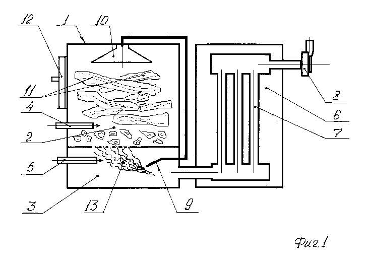
The design of the claimed heating device is illustrated by the sketch on FIG.
1, which shows a
vertical section of the version having a gas collection funnel but no
condensate collecting tank.
The heating device comprises a solid fuel hopper 1 with a loading hatch 12,
gasification zone
(chamber) 2 located in the lower part of the hopper, afterburner 3, primary
air supply ducts 4,
secondary air supply ducts 5, water tank 6 housing a fire-tube heat exchanger
7 connected to the
3
CA 03074239 2019-12-16
smoke exhauster 8 via the outlet chimney. The additional gas duct 9, connected
in its upper part to
the gas collection funnel 10, passes downwards to the afterburner, and its
lower opening is located
at the end of the flame (along the direction of movement of combustible
gases).
The heating device operates as follows. Wood fuel 11 (for example, firewood or
wood chips with
a natural moisture content) is loaded into the hopper 1 through the loading
hatch 12 on the side
wall of the hopper. Due to gravity, the wood fuel falls down, successively
passing through the
drying zone (upper part of the hopper), the dry distillation zone (lower part
of the hopper) and
enters the gasification zone (chamber) 2. In this zone, the fuel is ignited
from an external source
(not shown) and burns in the atmosphere of primary air supplied to the
gasification and primary
combustion zones through duct 4.
Combustible gases (hydrogen, methane, carbon monoxide), formed as a result of
primary pyrolysis
of wood and chemical reduction after contact with hot coal, enter the
afterburner 3, where they are
mixed with secondary air entering through duct 5 and burned in the flame 13.
The hot combustion
products from the afterburner enter the fire tube 7, where they transfer their
heat to the water in
tank 6 and are then discharged into the exhaust pipe with a smoke exhauster 8,
from there into the
chimney (not shown) and then to the atmosphere.
Moisture evaporating from raw wood in the form of water vapor with a
temperature of 100-120 C
rises ("floats") to the upper part of the fuel hopper 1 and enters the
additional gas duct 9 through a
gas collection funnel 10. The movement of water vapor from the top of the
additional gas duct 9 to
the bottom occurs under the influence of rarefaction (differential pressure)
created by the smoke
exhauster 8 in the afterburner 3; furthermore, the difference in the specific
gravity of the steam
having a temperature of 100-120 C and the combustion products in the
afterburner having a
temperature of more than 800-900 C contributes to the movement of steam from
the top of the
additional gas duct 9 to the bottom. The removal of or at least a significant
reduction in the amount
of water vapor in the primary combustion zone, contributes to the sustainable
burning of wood fuel.
Water vapor through the additional gas duct 9 is supplied to the end point of
the torch 13 (in the
direction of movement of the combustible gases). In this zone, the mixing of
combustible gases
and the secondary air has already been completed, and therefore the appearance
of water vapor will
not interfere with the combustion process. Carbon monoxide, a certain amount
of which will
inevitably be present in the stream of water vapor, caught in the zone of high
temperatures (more
4
CA 03074239 2019-12-16
than 900 C) in the most heated part of the torch 13 burns in the secondary
air.
The complete afterburning of carbon monoxide is also promoted by water vapor,
which reacts with
carbon monoxide at high temperatures according to the formula: H20 + CO = H2 +
CO2 . As a
result of the reaction, two gases harmless to human health are formed
(hydrogen and carbon
dioxide). This reaction is accompanied by heat, and thus does not interfere
with the main
combustion process in the afterburner. In addition, at high temperatures,
water vapor reacts with
the smallest particles of unburned coal (soot) and burns them according to the
formula: H20 + C
= H2 + CO, and an insignificant amount of carbon monoxide resulting from the
reaction is burned
according to the reactions described above. The possibility for destroying
(afterburning) the
.. smallest particles of coal (soot) is very important, because according to
modern data, these particles
are a strong carcinogen, and their content in flue gases should be strictly
limited.
5