Note: Descriptions are shown in the official language in which they were submitted.
FASTENER AND METHODS OF MANUFACTURING AND USE
FIELD
The present disclosure relates generally to a fastener, and more particularly,
to
a fastener including a plurality of textured elements positioned on a head of
the
fastener.
BACKGROUND
Fasteners are used in many manufacturing applications, including aerospace
manufacturing. When certain fasteners are installed in workpiece, a sealant
may be
initially applied to at least a portion of the fastener, and then the fastener
is positioned
in a hole in the workpiece. As the fastener is secured to the workpiece (e.g.,
during
the forming of the bulb of a one-sided fastener), the sealant can create a
hydraulic
lock between the head of the fastener and the top of the hole. When this
happens,
the trapped sealant can expand into the hole and can create bulges in or
otherwise
damage the workpiece. In addition, as the fastener is secured to the
workpiece,
mechanics struggle to prevent the fastener from spinning, especially when
there is
sealant applied under a head of the fastener and along a shank of the
fastener. In
the situation of a one-sided fastener, for example, the fastener tends to spin
and the
frangible drive element does not break off at the intended torque.
1
Date Recue/Date Received 2023-07-24
SUMMARY
In one aspect, a fastener is described. The fastener includes (a) an elongated
body having a first end and a second end opposite the first end, (b) a head
having a
first surface and a second surface opposite the first surface, wherein the
first end of
the elongated body is coupled to the second surface of the head, and wherein a
diameter of the head is greater than a diameter of the elongated body, (c) a
sleeve
positioned over the elongated body extending from the second end of the
elongated
body to the first end of the elongated body and extending from the first end
of the
elongated body over the second surface of the head and up to the first surface
of the
head, and (d) a plurality of textured elements positioned on an exterior
surface of the
sleeve only along a portion of the sleeve adjacent the second surface of the
head,
wherein the plurality of textured elements extend from the exterior surface of
the
sleeve , wherein a depth of each of the plurality of grooves ranges from about
0.0005
inches to about 0.02 inches.
In another aspect, a method of manufacturing a fastener is described. The
method includes (a) forming an elongated body having a first end and a second
end
opposite the first end, (b) forming a head having a first surface and a second
surface
opposite the first surface, wherein the first end of the elongated body is
coupled to the
second surface of the head, and wherein a diameter of the head is greater than
a
diameter of the elongated body, (c) forming a sleeve positioned over the
elongated
body extending from the second end of the elongated body to the first end of
the
elongated body and extending from the first end of the elongated body over the
second
surface of the head and up to the first surface of the head, and (d) forming a
plurality
of textured elements on an exterior surface of the sleeve only along a portion
of the
sleeve adjacent the second surface of the head, wherein the plurality of
textured
elements comprises a plurality of grooves recessed in the exterior surface of
the
sleeve, wherein a depth of each of the plurality of grooves ranges from about
0.0005
inches to about 0.02 inches.
2
Date Recue/Date Received 2023-07-24
In yet another aspect, a method for positioning the fastener described above,
in
a workpiece is described. The method includes (a) positioning a sealant on at
least a
portion of the fastener, (b) inserting the second end of the elongated body of
the
fastener into a hole in the workpiece, and (c) mating an exterior surface of
the sleeve
adjacent the second surface of the head to a surface in the hole, wherein a
plurality of
textured elements on the exterior surface of the sleeve are configured to
create friction
between the fastener and the surface in the hole to inhibit rotation of the
fastener and
to further allow the sealant to flow out from under the head of the fastener.
In another aspect, there is provided a fastener comprising an elongated body
having a first end and a second end opposite the first end, the elongate body
also
having a head having a first surface and a second surface opposite the first
surface,
wherein the first end of the elongated body is coupled to the second surface
of the
head, and wherein a diameter of the head is greater than a diameter of the
elongated
body. The fastener further includes a sleeve positioned over at least a
portion of the
elongated body and the second surface of the head and a plurality of textured
elements positioned on an exterior surface of the sleeve adjacent the second
surface
of the head wherein the plurality of textured elements extends on the exterior
surface
of the sleeve from the first end of the elongated body to the first surface of
the head
only.
In yet another aspect, there is provided a method of manufacturing a fastener.
The method involves forming an elongated body having a first end and a second
end
opposite the first end; forming a head having a first surface and a second
surface
opposite the first surface, wherein the first end of the elongated body is
coupled to the
second surface of the head, and wherein a diameter of the head is greater than
a
diameter of the elongated body; forming a sleeve positioned over at least a
portion of
the elongated body and the second surface of the head; and forming a plurality
of
textured elements on an exterior surface of the sleeve adjacent the second
surface of
the head, wherein the plurality of textured elements extends on the exterior
surface of
the sleeve from the first end of the elongated body to the first surface of
the head only.
3
Date Recue/Date Received 2023-07-24
The features, functions, and advantages that have been discussed can be
achieved independently in various examples or may be combined in yet other
examples further details of which can be seen with reference to the following
description and figures.
BRIEF DESCRIPTION OF THE FIGURES
The illustrative examples, however, as well as a preferred mode of use,
further
objectives and descriptions thereof, will best be understood by reference to
the
following detailed description of an illustrative examples of the present
disclosure
when read in conjunction with the accompanying figures.
Figure 1 is a block diagram of an example fastener, according to an example
embodiment.
Figure 2A is a side view of an example fastener, according to an example
embodiment.
Figure 2B is a side view of another example fastener, according to an example
embodiment.
Figure 2C is a side view of another example fastener, according to an example
embodiment.
Figure 2D is a side view of another example fastener, according to an example
embodiment.
Figure 3 is a flowchart of an example method, according to an example
embodiment.
Figure 4 is an example computer-readable medium configured according to an
example implementation to cause a manufacturing machine to create one or more
components of the fastener of Figures 1-2D.
Figure 5 is a flowchart of another example method, according to an example
embodiment.
4
Date Recue/Date Received 2023-07-24
DETAILED DESCRIPTION
Disclosed embodiments will now be described more fully hereinafter with
reference to the accompanying figures, in which some, but not all of the
disclosed
embodiments are shown. Indeed, several different embodiments may be provided
and
should not be construed as limited to the embodiments set forth herein.
Rather, these
embodiments are provided so that this disclosure will be thorough and complete
and
will fully convey the scope of the disclosure to those skilled in the art.
In the following description, numerous specific details are set forth to
provide a
thorough understanding of the disclosed concepts, which may be practiced
without
some or all of these particulars. In other instances, details of known devices
and/or
processes have been omitted to avoid unnecessarily obscuring the disclosure.
While
some concepts will be described in conjunction with specific examples, it will
be
understood that these examples are not intended to be limiting.
In Figure 1, solid lines, if any, connecting various elements and/or
components
may represent mechanical, electrical, fluid, optical, electromagnetic and
other
couplings and/or combinations thereof. As used herein, "coupled" means
associated
directly as well as indirectly. For example, a member A may be directly
associated
with a member B, or may be indirectly associated therewith, e.g., via another
member
C. It will be understood that not all relationships among the various
disclosed
elements are necessarily represented. Accordingly, couplings other than those
depicted in the block diagrams may also exist. Dashed lines, if any,
connecting blocks
designating the various elements and/or components represent couplings similar
in
function and purpose to those represented by solid lines; however, couplings
represented by the dashed lines may either be selectively provided or may
relate to
alternative examples of the present disclosure.
Likewise, elements and/or
components, if any, represented with dashed lines, indicate alternative
examples of
the present disclosure. One or more elements shown in solid and/or dashed
lines
may be omitted from a particular example without departing from the scope of
the
present disclosure. Environmental elements, if any, are represented with
dotted lines.
Date Recue/Date Received 2023-07-24
Virtual (imaginary) elements may also be shown for clarity. Those skilled in
the art will
appreciate that some of the features illustrated in Figure 1 may be combined
in various
ways without the need to include other features described in Figure 1, other
drawing
figures, and/or the accompanying disclosure, even though such combination or
combinations are not explicitly illustrated herein. Similarly, additional
features not
limited to the examples presented, may be combined with some or all of the
features
shown and described herein.
In Figures 3 and 5, the blocks may represent operations and/or portions
thereof
and lines connecting the various blocks do not imply any particular order or
dependency of the operations or portions thereof. It will be understood that
not all
dependencies among the various disclosed operations are necessarily
represented.
Figures 3 and 5 and the accompanying disclosure describing the operations of
the
method(s) set forth herein should not be interpreted as necessarily
determining a
sequence in which the operations are to be performed. Rather, although one
illustrative order is indicated, it is to be understood that the sequence of
the operations
may be modified when appropriate. Accordingly, certain operations may be
performed
in a different order or simultaneously. Additionally, those skilled in the art
will
appreciate that not all operations described need be performed.
Unless otherwise indicated, the terms "first," "second," etc. are used herein
merely as labels, and are not intended to impose ordinal, positional, or
hierarchical
requirements on the items to which these terms refer. Moreover, reference to,
e.g., a
"second" item does not require or preclude the existence of, e.g., a "first"
or lower-
numbered item, and/or, e.g., a "third" or higher-numbered item.
Reference herein to "one embodiment" or "one example" means that one or more
feature, structure, or characteristic described in connection with the example
is
included in at least one implementation. The phrases "one embodiment" or "one
example" in various places in the specification may or may not be referring to
the same
exam pie.
As used herein, a system, apparatus, device, structure, article, element,
component, or hardware "configured to" perform a specified function is indeed
capable
6
Date Recue/Date Received 2023-07-24
of performing the specified function without any alteration, rather than
merely having
potential to perform the specified function after further modification. In
other words,
the system, apparatus, structure, article, element, component, or hardware
"configured to" perform a specified function is specifically selected,
created,
implemented, utilized, programmed, and/or designed for the purpose of
performing
the specified function. As used herein, "configured to" denotes existing
characteristics
of a system, apparatus, structure, article, element, component, or hardware
which
enable the system, apparatus, structure, article, element, component, or
hardware to
perform the specified function without further modification. For purposes of
this
disclosure, a system, apparatus, structure, article, element, component, or
hardware
described as being "configured to" perform a particular function may
additionally or
alternatively be described as being "adapted to" and/or as being "operative
to" perform
that function.
As used herein, with respect to measurements, "about" and "substantially" each
means +/- 5%.
Illustrative, non-exhaustive examples of the subject matter according to the
present disclosure are provided below.
Within examples, a fastener and methods of manufacturing and use are
described herein. As discussed above, existing fasteners can experience
hydraulic
lock between the head of the fastener and the top of the hole into which the
fastener
is positioned as the fastener is secured to a workpiece. The trapped sealant
can
expand into the hole and can create bulges in or otherwise damage the
workpiece. In
addition, as traditional fasteners are secured to the workpiece, the elongated
portion
of the fastener can spin, which may prevent the frangible drive element of a
one-sided
fastener from breaking off at the intended torque. Existing solutions result
in increased
cost and/or decreased performance of the fastener.
The present disclosure provides an improved fastener that includes a plurality
of
textured elements providing a pattern of light texture applied on the surface
adjacent
the head of the fastener. The plurality of textured elements are thin and can
be rolled
or forged on a surface adjacent the head of the fastener that will come in
contact with
7
Date Recue/Date Received 2023-07-24
the workpiece once installed. The plurality of textured elements will give a
sealant
positioned in the hole of the workpiece many different pathways to flow during
the
torqueing of the fastener, and will also create more friction between the
fastener and
the surface of the workpiece.
Various other features of the example fastener discussed above, as well as
methods for manufacturing and using these fasteners, are also described
hereinafter
with reference to the accompanying Figures.
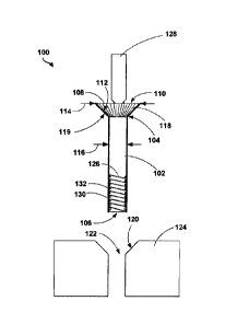
With reference to the Figures, Figure 1 illustrates a fastener 100 according
to an
example embodiment. As shown in Figure 1, the fastener 100 includes an
elongated
body 102 having a first end 104 and a second end 106 opposite the first end
104. The
fastener 100 also includes a head 108 having a first surface 110 and a second
surface
112 opposite the first surface 110. The first end 104 of the elongated body
102 is
coupled to the second surface 112 of the head 108. In one example, the
elongated
body 102 and the head 108 are formed integrally as a single unit. In another
example,
the elongated body 102 and the head 108 are formed separately and are coupled
together during manufacturing. As shown in Figures 2A-2D, a diameter 114 of
the
head 108 is greater than a diameter 116 of the elongated body 102. The
fastener 100
also includes a sleeve 130 positioned over at least a portion of the elongated
body
102 and the second surface 112 of the head 108. The fastener 100 also includes
a
plurality of textured elements 118 positioned on an exterior surface 119 of
the sleeve
130 adjacent the second surface 112 of the head 108. One or more of the
plurality of
textured elements 118 extend from the exterior surface 119 of the sleeve 130
to the
first surface 110 of the head 108.
In another example, the plurality of textured elements 118 may be positioned
directly on the second surface 112 of the head 108. In such an example, one or
more
of the plurality of textured elements 118 extend from the second surface 112
of the
head 108 to the first surface 110 of the head 108.
As shown in Figures 2A-2D, the plurality of textured elements 118 can take a
variety of forms. In particular, as shown in Figure 2A, the plurality of
textured elements
118 comprise a straight line pattern. In another example, as shown in Figure
2B, the
8
Date Recue/Date Received 2023-07-24
plurality of textured elements 118 comprise a diagonal line pattern. In
another
example, as shown in Figure 2C, the plurality of textured elements 118
comprise a
sinusoidal line pattern. In yet another example, as shown in Figure 2D, the
plurality
of textured elements 118 comprise a waffle pattern. Other patterns for the
plurality of
textured elements 118 are possible as well.
As described above and as shown in Figures 2A-2D, one or more of the plurality
of textured elements 118 extend from the exterior surface 119 of the sleeve
130 to the
first surface 110 of the head 108. Such an arrangement provides a path to
allow
sealant to flow out from under the head 108 of the fastener 100. In one
example, one
or more of the plurality of textured elements 118 extend on the exterior
surface of the
sleeve from the first end 104 of the elongated body 102 to the first surface
110 of the
head 108 of the fastener 100. Such an arrangement may help to increase the
friction
between the fastener 100 and a surface 120 in the hole 122 in a workpiece 124
to
inhibit rotation of the fastener 100, as discussed in additional detail below.
In one example, as shown in Figures 2A-2C, each of the plurality of textured
elements 118 are parallel to one another. Such an arrangement may provide a
more
uniform path for sealant to flow out from under the head 108 of the fastener
100 when
installed in the hole 122 in the workpiece 124. In another example, as shown
in Figure
2D, one or more of the plurality of textured elements 118 intersect one
another. Such
an arrangement may provide increased friction between the fastener 100 and the
surface 120 in the hole 122 to inhibit rotation of the fastener 100 during
installation. In
yet another example, the plurality of textured elements 118 form a non-
repeating or
random pattern. Other examples are possible as well.
As shown in Figures 2A-2D, in one embodiment at least a portion of the
elongated body 102 includes a plurality of threads 126 defined by a plurality
of crests
and a plurality of roots. In one example, the plurality of threads 126 may
help with
installation of the fastener 100 when in use by securing the elongated body
102 in the
hole 122 in the workpiece 124. Further, as shown in Figures 2A-2D, the second
surface 112 of the head 108 of the fastener 100 may taper from the first
surface 110
of the head 108 to the first end 104 of the elongated body 102. The sleeve 130
may
9
Date Recue/Date Received 2023-07-24
include a similar taper in the area surrounding the head 108 of the fastener
100. Such
an arrangement may provide a snug fit for the head 108 of the fastener 100 in
the hole
122 in the workpiece 124 when the hole 122 is countersunk into the workpiece
124.
In one embodiment, the plurality of textured elements 118 comprise a plurality
of
grooves recessed in the exterior surface 119 of the sleeve 130. In such an
example,
a depth of each of the plurality of grooves ranges from about 0.0005 inches to
about
0.02 inches. The plurality of grooves provide a plurality of paths for sealant
to escape
from under the second surface 112 of the head 108 of the fastener 100 when the
fastener 100 is position in the hole 122 in the workpiece 124, thereby
preventing
hydraulic lock between the fastener 100 and the surface 120 of the hole 122.
In
addition, the plurality of grooves are configured to increase the friction
between the
fastener 100 and the surface 120 in the hole 122 to inhibit rotation of the
fastener 100
during installation.
In another embodiment, the plurality of textured elements 118 comprise a
plurality of protrusions extending outward from the exterior surface 119 of
the sleeve
130. In such an example, a height of each of the plurality of protrusions
ranges from
about 0.0005 inches to about 0.02 inches. The space between the plurality of
protrusions provide a plurality of paths for sealant to escape from under the
head 108
of the fastener 100 when the fastener 100 is position in the hole 122 in the
workpiece
124, thereby preventing hydraulic lock between the fastener 100 and the
surface 120
of the hole 122. In addition, the plurality of protrusions are configured to
increase the
friction between the fastener 100 and the surface 120 in the hole 122 to
inhibit rotation
of the fastener 100 during installation.
The fastener 100 may further include a drive 128 formed in the first surface
110
of the head 108. In one example, as shown in Figures 2A-2D, the drive 128
comprises
a frangible component configured to break off from the first surface 110 of
the head
108 after the fastener 100 is torqued to a desired level. In another example,
the drive
128 comprises a polygonal recess formed in the first surface 110 of the head
108 that
is configured to receive a corresponding polygonal driver. In yet another
example, the
drive 128 comprises a plurality of radially extending slots recessed in the
first surface
Date Recue/Date Received 2023-07-24
110 of the head 108 that is configured to receive corresponding radially
extending
protrusions of a driver. In each example described above, the drive 128
provides a
surface onto which a corresponding driver is able to rotate the fastener 100
to thereby
install the fastener 100 in the hole 122 in the workpiece 124.
As discussed above, the fastener 100 can take a variety of forms. In one
embodiment, as shown in Figures 2A-2D, the fastener 100 comprises a one-sided
fastener. In such an example, as discussed above, the fastener 100 includes a
sleeve
130 positioned over at least a portion of the elongated body 102 and the
second
surface 112 of the head 108. The sleeve 130 may include a threaded locking
feature
132 configured to interact with the plurality of threads 126 of the elongated
body 102.
In use, as the drive 128 is rotated, a portion of the sleeve 130 deforms and
compresses
against the backside of the workpiece 124 to thereby secure the fastener 100
to the
workpiece 124. Once the fastener 100 is torqued to a desired level, the drive
128 is
configured to break off from the first surface 110 of the head 108.
In another embodiment, the fastener 100 comprises a flush head fastener. In
such an example, the plurality of textured elements 118 may be positioned
directly on
the second surface 112 of the head 108, and one or more of the plurality of
textured
elements 118 extend from the second surface 112 of the head 108 to the first
surface
110 of the head 108In yet another embodiment, the fastener 100 comprises a
protruding head fastener. In such an example, the second surface 112 of the
head
108 of the fastener 100 is parallel to the first surface 110 of the head 108
of the
fastener 100. As with the flush head fastener embodiment, in the protruding
head
fastener example the plurality of textured elements 118 may be positioned
directly on
the second surface 112 of the head 108, and one or more of the plurality of
textured
elements 118 extend from the second surface 112 of the head 108 to the first
surface
110 of the head 108. Other fastener types are possible as well.
Figure 3 is a block diagram of an example of a method 200 of manufacturing a
fastener. Method 200 shown in Figure 3 presents an embodiment of a method that
could be used to manufacture the fastener 100 described above in relation to
Figures
1-2D, as an example. Method 200 includes one or more operations, functions, or
11
Date Recue/Date Received 2023-07-24
actions as illustrated by one or more of blocks 202-208. Although the blocks
are
illustrated in a sequential order, these blocks may also be performed in
parallel, and/or
in a different order than those described herein. Also, the various blocks may
be
combined into fewer blocks, divided into additional blocks, and/or removed
based
upon the desired implementation.
Initially, at block 202, the method 200 includes forming an elongated body 102
having a first end 104 and a second end 106 opposite the first end 104. At
block 204,
the method 200 includes forming a head 108 having a first surface 110 and a
second
surface 112 opposite the first surface 110. The first end 104 of the elongated
body
102 is coupled to the second surface 112 of the head 108. In one example, the
elongated body 102 and the head 108 are formed integrally as a single unit. In
another
example, the elongated body 102 and the head 108 are formed separately and are
coupled together during the manufacturing process. A diameter 114 of the head
108
is greater than a diameter 116 of the elongated body 102. At block 206, the
method
200 includes forming a sleeve 130 positioned over at least a portion of the
elongated
body 102 and the second surface 112 of the head 108. At block 208, the method
200
includes forming a plurality of textured elements 118 on an exterior surface
119 of the
sleeve 130 adjacent the second surface 112 of the head 108. As discussed
above,
one or more of the plurality of textured elements 118 extend from the exterior
surface
119 of the sleeve 130 to the first surface 110 of the head 108.
In one example, forming the plurality of textured elements 118 on the second
surface 112 of the head 108 comprises rolling the plurality of textured
elements 118.
In another example, forming the plurality of textured elements 118 on the
second
surface 112 of the head 108 comprises forging the plurality of textured
elements 118.
In yet another example, forming the plurality of textured elements 118 on the
second
surface 112 of the head 108 comprises laser engraving or texturing the
plurality of
textured elements 118. Other embodiments are possible as well.
In another example, the method 200 may include forming a plurality of textured
elements 118 on the second surface 112 of the head 108 of the fastener 100. In
such
12
Date Recue/Date Received 2023-07-24
an example, one or more of the plurality of textured elements 118 extend from
the
second surface 112 of the head 108 to the first surface 110 of the head 108.
In certain embodiments, one or more steps of the method 200 described above
in relation to Figure 3 may be performed by an additive-manufacturing machine,
such
as stereolithography, multi-jet modeling, inkjet printing, selective laser
sintering/melting, and fused filament fabrication, among other possibilities.
In one
example, the additive-manufacturing machine creates the fastener 100 described
in
any one of Figures 1-2B using a single material. Such a material includes
stainless
steel, titanium, nickel super-alloy, aluminum, polymer composites (e.g.,
carbon fiber
reinforced nylon) and polymer nanocomposites (e.g., carbon nanotube filled
nylon),
polyether ether ketone (PEEK), polyethylene (PE), or polypropylene (PP), as
examples. In another example, the additive-manufacturing process is a multi-
material
additive-manufacturing process such that various components of the fastener
100 are
formed using a material with a material property than the other components.
Other
examples are possible as well.
Additionally or alternatively, the manufacturing processes described above may
be controlled by non-transitory computer-readable medium. Figure 4 depicts an
example non-transitory computer-readable medium configured according to an
example implementation. In example implementations, the system may include one
or more processors, one or more forms of memory, one or more input
devices/interfaces, one or more output devices/interfaces, and machine
readable
instructions that, when executed by the one or more processors, cause
manufacturing
machine to create one or more components of the fastener 100 of any of the
examples
described above with respect to Figures 1-2D.
In one implementation, the example computer program product 300 is provided
using a signal bearing medium 302. The signal bearing medium 302 may include
one
or more programming instructions 304 that, when executed by one or more
processors
may cause manufacturing machine to create one or more components of the
fastener
100 of any of the embodiments described above with respect to Figures 1-2D. In
some examples, the signal bearing medium 302 may be a non-transitory computer-
13
Date Recue/Date Received 2023-07-24
readable medium 306, such as, but not limited to, a hard disk drive, a Compact
Disc
(CD), a Digital Video Disk (DVD), a digital tape, memory, etc. In
some
implementations, the signal bearing medium 302 may be a computer recordable
medium 308, such as, but not limited to, memory, read/write (R/VV) CDs, R/W
DVDs,
etc. In some implementations, the signal bearing medium 302 may be a
communications medium 310 (e.g., a fiber optic cable, a waveguide, a wired
communications link, etc.). Thus, for example, the signal bearing medium 302
may
be conveyed by a wireless form of the communications medium 310.
The one or more programming instructions 304 may be, for example, computer
executable and/or logic implemented instructions. In some examples, a
computing
device may be configured to provide various operations, functions, or actions
in
response to the programming instructions 304 conveyed to the computing device
by
one or more of the non-transitory computer-readable medium 306, the computer
recordable medium 308, and/or the communications medium 310.
The non-transitory computer-readable medium 306 may also be distributed
among multiple data storage elements, which could be remotely located from
each
other. The computing device that executes some or all of the stored
instructions could
be an external computer, or a mobile computing platform, such as a smartphone,
tablet
device, personal computer, wearable device, etc. Alternatively, the computing
device
that executes some or all of the stored instructions could be a remotely
located
computer system, such as a server.
Figure 5 is a block diagram of an example of a method 400 for positioning a
fastener in a workpiece. Method 400 shown in Figure 5 presents an embodiment
of a
method that could be carried out using the fastener 100 described above in
relation to
Figures 1-2D, as an example. Method 400 includes one or more operations,
functions,
or actions as illustrated by one or more of blocks 402-406. Although the
blocks are
illustrated in a sequential order, these blocks may also be performed in
parallel, and/or
in a different order than those described herein. Also, the various blocks may
be
combined into fewer blocks, divided into additional blocks, and/or removed
based
upon the desired implementation.
14
Date Recue/Date Received 2023-07-24
Initially, at block 402, the method 400 includes positioning a sealant on at
least
a portion of the fastener 100. The sealant may be positioned on the sleeve
130, or
other exterior surface of the fastener 100. At block 404, the method 400
includes
inserting a second end 106 of an elongated body 102 of a fastener 100 into the
hole
122 in the workpiece 124. The fastener 100 may include any of the features of
the
fastener 100 described above in relation to Figures 1-2D. In particular, the
fastener
100 includes a first end 104 opposite the second end 106, and a head 108
having a
first surface 110 and a second surface 112 opposite the first surface 110. The
first
end 104 of the elongated body 102 is coupled to the second surface 112 of the
head
108 of the fastener 100. The fastener 100 may also include a sleeve 130
positioned
over at least a portion of the elongated body 102 and the second surface 112
of the
head 108.
At block 406, the method 400 includes mating an exterior surface 119 of the
sleeve 130 adjacent the second surface 112 of the head 108 to a surface 120 in
the
hole 122. As described above, the fastener 100 includes a plurality of
textured
elements 118 positioned on the exterior surface 119 of the sleeve 130 adjacent
the
second surface 112 of the head 108. In use, the plurality of textured elements
118 are
configured to create friction between the fastener 100 and the surface 120 in
the hole
122 to inhibit rotation of the fastener 100. Further, the plurality of
textured elements
118 allow the sealant to flow out from under the head 108 of the fastener 100
by
providing a plurality of flow paths for the sealant to thereby prevent
hydraulic lock
between the fastener 100 and the surface 120 of the hole 122.
In one embodiment, the method 400 further includes rotating the fastener 100
after inserting the second end 106 of the elongated body 102 of the fastener
100 into
the hole 122 in the workpiece 124. In one particular example, rotating the
fastener
100 comprises rotating a drive 128 formed in the first surface 110 of the head
108. As
discussed above, the drive 128 may comprise a frangible component configured
to
break off from the first surface 110 of the head 108 after the fastener 100 is
torqued
to a desired level. In such an example, rotating the fastener 100 may cause
the sleeve
130 to deform and compress against the backside of the workpiece 124 to
thereby
Date Recue/Date Received 2023-07-24
secure the fastener 100 to the workpiece. In another example, the drive 128
comprises a polygonal recess formed in the first surface 110 of the head 108
that is
configured to receive a corresponding polygonal driver. In yet another
example, the
drive 128 comprises a plurality of radially extending slots recessed in the
first surface
110 of the head 108 that is configured to receive corresponding radially
extending
protrusions of a driver.
In another example, as discussed above, the plurality of textured elements 118
may be positioned directly on the second surface 112 of the head 108. In such
an
example, one or more of the plurality of textured elements 118 extend from the
second
surface 112 of the head 108 to the first surface 110 of the head 108. Further,
in such
an example, the method 400 includes mating the second surface 112 of the head
108
of the fastener 100 to the surface 123 in the hole 122.
The description of the different advantageous arrangements has been presented
for purposes of illustration and description, and is not intended to be
exhaustive or
limited to the examples in the form disclosed. Many modifications and
variations will
be apparent to those of ordinary skill in the art. Further, different
advantageous
examples may provide different advantages as compared to other advantageous
examples. The example or examples selected are chosen and described in order
to
best explain the principles of the examples, the practical application, and to
enable
others of ordinary skill in the art to understand the disclosure for various
examples
with various modifications as are suited to the particular use contemplated.
16
Date Recue/Date Received 2023-07-24