Note: Descriptions are shown in the official language in which they were submitted.
AIR INTAKE ASSEMBLY FOR CENTRIFUGAL BLOWER SYSTEM AND
FUEL CELL INCORPORATING SAME
BACKGROUND OF THE INVENTION
[0001] This invention relates to centrifugal blowers and to fuel cells
incorporating same,
and more particularly to an air intake assembly for centrifugal blowers.
[0002] Centrifugal blowers, or centrifugal fans, are a well-known type of
device for
providing a flow or movement of a gaseous medium. A common type of centrifugal
blower
includes a housing having an axially directed gas inlet and a radially
directed gas outlet, an
impeller disposed within the housing for drawing gas at a first pressure into
the inlet and
expelling gas at a second higher pressure through the outlet and a motor for
driving, i.e.,
spinning, the impeller. Variations of this general type of centrifugal blower
are disclosed in, e.g.,
U.S. Patent Nos. 4,917,572; 5,839,879; 6,877,954; 7,061,758; 7,351,031;
7,887,290; 7,891,942,
and, U.S. 2006/0051203,
[0003] Centrifugal blowers in single unit and multiple independent unit
configurations
have been disclosed as components of cooling systems for computers, servers
and other heat-
generating electrical and electronic devices and equipment. See, e.g., U.S.
Patent Nos. 6,525,935;
7,184,265; 7,744,341; 7,802,617; 7,864,525; 7,885,068; 7,948,750; 7,902,617;
and, 7,885,068.
[0004] Centrifugal blowers of the general type referred to above have been
disclosed as
components of fuel cells, of both the polyelectrolyte membrane (PEM) and solid
oxide fuel cell
(SOFC) types, and chemical reformers, where they function in one or more
capacities, e.g.,
1
Date Recue/Date Received 2023-04-04
providing a flow of an oxidizer-containing gas such as air to the cathode
elements of the fuel cell
assembly and/or a flow of gaseous or vaporized fuel to its anode elements,
recycling unspent fuel
to the anode elements of the fuel cell assembly, providing a stream of cool
air for cooling the
fuel cell assembly or providing a stream of hot gas for vaporizing a liquid
fuel prior to the
external or internal reforming of the fuel to provide hydrogen for the
operation of the fuel cell
assembly. Fuel cell-blower assemblies featuring one or more centrifugal
blowers are described
in, e.g., U.S. Patent Nos. 6,497,971; 6,830,842; 7,314,679 and 7,943,260,
100051 During normal operations, fuel cell assemblies heat to temperatures
ranging from
350 C up to and exceeding 900 C. The components of the fuel cell assemblies
are designed to
maintain their mechanical, chemical, and/or electrical integrity during start
up and normal
operating modes. During a cool-down period, whether transitioning into a low
power mode or
power down procedure, problems can arise. For example, when the system is
cooling down, the
air inside a fuel cell assembly can condense and create a vacuum in the fuel
cell assembly that
would continue to draw outside air through an air inlet, or could also draw
exhaust and possibly
outside air back through the exhaust of the fuel cell assembly. The exposure
of the fuel cell
assembly to this additional air or exhaust can result in damaging oxidation of
the fuel cell stack.
100061 Many fuel cell assemblies and reformers utilize ambient air as a
source of oxygen
for the electrical and chemical reactions occurring therein as well as for
temperature control
within the units. Ambient air usually includes particulates (e.g., dirt/dust),
contaminants (e.g.
sulfur, hydrocarbons), and/or moisture, each of which can damage the fuel cell
and reformer
units.
2
Date Recue/Date Received 2023-04-04
CA 03074863 2020-03-04
WO 2019/055472 PCT/US2018/050593
SUMMARY OF THE INVENTION
[0007] In accordance with the present invention, there is provided a
centrifugal blower
air intake apparatus comprising: a blower unit, comprising: a blower casing
having an axial inlet
and a radial outlet; an impeller disposed within the casing for drawing a
gaseous medium at a
first pressure into the axial inlet and expelling gaseous medium at a second
higher pressure
through the radial outlet; and a motor for driving the impeller; and an air
intake assembly,
comprising: an air intake assembly casing having an air inlet and an air
outlet, the air outlet
connected to the axial inlet of the blower casing of the blower unit; and a
check valve mounted
within the casing positioned to permit air flow from the air inlet through to
the air outlet and
prevent air flow from the air outlet through to the air inlet.
[00081 Further in accordance with the present invention there is provided
an air intake
assembly for a centrifugal blower system comprising: a series of blower units,
each blower unit
in the series comprising a blower unit casing having an axial inlet and a
radial outlet, an impeller
disposed within the blower unit casing for drawing a gaseous medium at a first
pressure into the
axial inlet and expelling gaseous medium at a second higher pressure through
the radial outlet,
and a motor for driving the impeller; a duct connecting the radial outlet of
at least one blower
unit in the series of blower units with the axial inlet of at least one other
blower unit in the series
of blower units; and an air intake assembly, comprising an air intake assembly
casing having an
air inlet and an air outlet, the air outlet connectable to the axial inlet of
the blower unit casing of
a first blower unit of the series of blower units, and a check valve mounted
within the air intake
assembly casing positioned to permit air flow from the air inlet through to
the air outlet and
prevent air flow from the air outlet through to the air inlet.
100091 Further in accordance with the present invention there is provided
an air intake
3
CA 03074863 2020-03-04
WO 2019/055472 PCT/US2018/050593
assembly for a centrifugal blower having a casing having an axial inlet and a
radial outlet, an
impeller disposed within the casing for drawing a gaseous medium at a first
pressure into the
axial inlet and expelling gaseous medium at a second higher pressure through
the radial outlet,
and a motor for driving the impeller, comprising: an air intake assembly
casing having an air
inlet and an air outlet, the air outlet connectable to the axial inlet of the
blower casing of the
centrifugal blower; a check valve mounted within the air intake assembly
casing positioned to
permit air flow from the air inlet through the air intake assembly casing to
the air outlet and
prevent air flow from the air outlet through the air intake assembly casing to
the air inlet.
100010] The air intake assembly for the centrifugal blower system herein
offers several
advantages prior art centrifugal blowers, particularly when incorporated in a
fuel cell or fuel
reformer for managing the flow of gaseous media therein.
[00011] Filtration of the incoming air before the check valve can be used
to filter
particulates, volatile compounds, potentially sulfur compounds from
environment, desiccant to
reduce moisture.
[00012] Filtration of the incoming air after the check valve can be used
to filter
particulates, volatile compounds, potentially sulfur compounds from
environment, desiccant to
reduce moisture.
[00013] The check valve prevents zero flow conditions from getting back
flow from fans
and other process air. At high temperatures, this can damage the solid oxide
fuel cell (SOFC) and
catalysts by oxidation. The present invention can prevent this from occurring.
[00014] The filter can be reticulated foam (low pressure drops) of some
kind and
potentially doped with specific materials to perform the tasks enumerated
above.
4
[00015] The check valve can be a soft elastomer that induces very little
pressure drop to
open and uses the slight inherent stiffness and spring constant of the
material to close and seal.
[00016] Utilizing the multiple blower system of this invention for meeting
the gas flow
requirements of a fuel cell enables the system to benefit from both low
inertia impellers for
control as well as low drive motor rpm and power draw to provide required gas
flow and
pressure.
[00017] Thus, in its integrated, or interconnected, arrangement of multiple
centrifugal
blowers inherently possessing smaller inertial forces than a single
centrifugal blower of
comparable gas flow capability, the centrifugal blower system herein provides
improved
response times and control over a broad range of gas pressure and gas flow
requirements than
that of a single centrifugal blower unit. Fuel cell-blower assemblies
featuring this arrangement of
multiple centrifugal blowers are described in, e.g., U.S. Patent Nos.
9,017,893; 9,593,686 and
9,512,846.
[00018] Additional fuel cell-blower assemblies featuring this arrangement
of multiple
centrifugal blowers are described in, e.g., International Application No.
PCT/US2012/020707,
filed March 16,2015, and International Publication No. WO/2016/148681,
published September
22, 2016.
[0010] These and other novel features and advantages of this invention will
become more
apparent from the following detailed description and accompanying drawings.
BRIEF DESCRIPTION OF THE DRAWINGS
[0011] Fig. IA illustrates a perspective view of a dual blower system with
a section of
Date Recue/Date Received 2023-04-04
CA 03074863 2020-03-04
WO 2019/055472 PCT/US2018/050593
the duct cutaway to show a portion of the inlet and impeller of the second
blower unit to which
the air intake assembly according to the present disclosure can be applied;
[0012] Fig. 1B illustrates a plan view of the dual blower system of lA to
which the air
intake assembly according to the present disclosure can be applied;
[0013] Fig. 2 is a top plan view of the air intake assembly according to
the present
disclosure connected to the dual blower system;
[0014] Fig. 3 is a perspective view of the air intake assembly according
to the present
disclosure connected to the dual blower system;
[0015] Fig. 4 is a front plan view of the air intake assembly according
to the present
disclosure connected to the dual blower system;
100161 Fig. 5 is a side plan view of the air intake assembly according to
the present
disclosure connected to the dual blower system;
[0017] Fig. 6 is a cut-away perspective view of the air intake assembly
according to the
present disclosure connected to the dual blower system;
[0018] Fig. 7 is a cut-away perspective view of the air intake assembly
including a filter
component according to the present disclosure connected to the dual blower
system;
[0019] Figs. 8A and 8B are cut-away side plan views of the air intake
assembly including
multiple filter components according to various embodiments of the present
disclosure connected
to the dual blower system;
[0020] Fig. 9 is a block diagram of a control system of an air intake
assembly according
to the present disclosure for a dual blower system in accordance with the
invention;
6
CA 03074863 2020-03-04
WO 2019/055472 PCT/US2018/050593
[0021] Figs. 10A and 10B illustrate, respectively, perspective and plan
views of a tubular
SOFC assembly possessing separate dual blower systems having an air intake
assembly
according to the present disclosure of the invention for providing,
respectively, air and fuel flow
to the assembly;
[0022] Fig. 10C is a diagrammatic illustration of a cross section of an
individual tubular
fuel cell in the tubular SOFC assembly of Figs. 10A and 10B;
[0023] Figs. 11A and 11B illustrate, respectively, perspective and plan
views of a planar
SOFC assembly possessing separate dual blower systems having an air intake
assembly
according to the present disclosure of the invention for providing,
respectively, air and fuel flow
to the assembly; and,
[0024] Fig. 11C is a diagrammatic illustration of a cross section of an
individual planar
fuel cell in the planar SOFC assembly of Figs. 11A and 11B.
DETAILED DESCRIPTION OF THE INVENTION
[0025] The present disclosure may be understood more readily by reference
to the
following detailed description of the disclosure taken in connection with the
accompanying
drawing figures, which form a part of this disclosure. It is to be understood
that this disclosure is
not limited to the specific devices, methods, conditions or parameters
described and/or shown
herein, and that the terminology used herein is for the purpose of describing
particular
embodiments by way of example only and is not intended to be limiting of the
claimed
disclosure.
[0026] Also, as used in the specification and including the appended
claims, the singular
7
CA 03074863 2020-03-04
WO 2019/055472 PCT/US2018/050593
forms "a," "an," and "the" include the plural, and reference to a particular
numerical value
includes at least that particular value, unless the context clearly dictates
otherwise. Ranges may
be expressed herein as from "about" or "approximately" one particular value
and/or to "about" or
"approximately" another particular value. When such a range is expressed,
another embodiment
includes from the one particular value and/or to the other particular value.
Similarly, when values
are expressed as approximations, by use of the antecedent "about," it will be
understood that the
particular value forms another embodiment. It is also understood that all
spatial references, such
as, for example, horizontal, vertical, top, upper, lower, bottom, left and
right, are for illustrative
purposes only and can be varied within the scope of the disclosure.
100271 As discussed above, many fuel cell assemblies and/or reformers
utilize ambient
air as a source of oxygen for the electrical and chemical reactions occurring
therein. The ambient
air is also utilized to maintain proper operating temperatures in the fuel
cell assemblies and/or
reformers.
10028] Ambient air includes particulates, contaminants, and/or moisture
that can affect
the proper operation of the fuel cell assemblies and/or reformers. These
particulates, for dust or
dirt, contaminants, for example sulfur or hydrocarbons, and/or moisture, can
damage the fuel cell
and reformer units. This damage can be in the form of oxidation to the
internal components, hot
spots from accumulating particulates, or rapid cooling that can cause
structural defects in the
components, among others.
100291 The components of the fuel cell assemblies are designed to
maintain their
mechanical, chemical, and/or electrical integrity during start up and normal
operating modes as
exposed to the high operating temperatures. During cool-down periods, e.g.,
transitioning into a
low power mode or power down procedure, problems can arise.
8
CA 03074863 2020-03-04
WO 2019/055472 PCT/US2018/050593
[0030] For example, when the system is cooling down, the air inside a
fuel cell assembly
can condense and create a vacuum in the fuel cell assembly that can continue
to draw outside air
in through an air inlet and/or exhaust. The exposure of the fuel cell assembly
to this additional
outside air can result in damaging oxidation or structural integrity of the
fuel cell stack.
100311 Referring to Figs. lA and B, in one embodiment, a centrifugal
blower system is
described to which the air intake assembly according to the present disclosure
can be applied.
Dual centrifugal blower system 10 includes a first centrifugal blower unit 11
connected to a
second centrifugal blower unit 12 through duct 13. First blower unit 11
includes a blower casing
14 having an axial inlet 15 and a radial outlet 16, an impeller 17 disposed
within blower casing
14 for drawing a gaseous medium at a first pressure into axial inlet 15 and
expelling gaseous
medium at a second higher pressure through radial outlet 16 and an electric
motor 18 for driving
impeller 17. Second blower unit 12 includes a casing 19 and, as shown by the
cutaway section of
duct 13 in Fig. 1A, an impeller 20 disposed within casing 19 and driven by
electrical motor 21
and an axial inlet 22 for receiving gas medium discharged from outlet 16 of
first blower unit 11.
Second blower unit further includes a radial outlet 23 and outlet gas stream
housing 24.
[0032] The arrows in Figs. IA and 1B and in the other embodiments of the
invention
illustrated in other figures herein indicate the general direction of the gas
stream through the air
intake assembly and blower units in the series of blower units. As shown,
e.g., in Fig. 1B, the
trajectory of the gas stream expelled through outlet 16 of first blower unit
11 and the trajectory
of the gas stream expelled through outlet 23 of second blower unit 12 are not
parallel to their
respective outlets but are at some angle thereto. By arranging the geometry of
duct 13 to receive
the gas stream discharged through outlet 16 in such a manner that the stream
remains
approximately parallel to the interior walls of the duct, it is possible to
prevent or reduce the
9
CA 03074863 2020-03-04
WO 2019/055472 PCT/US2018/050593
turbulence that would otherwise occur were the stream to impinge upon these
walls. Turbulence
is advantageously minimized or avoided so as to reduce or eliminate it as a
source of back
pressure in the blower system. For this same reason, it is advantageous to
arrange the angle of
gas stream housing 24 so that its interior walls will be approximately
parallel to the trajectory of
the gas stream discharged through outlet 23 of second blower unit 12.
[00331 Figs. 2-5 illustrate dual centrifugal blower system 10 with air
intake assemble 100
attached to axial inlet 15. Air intake assembly includes an air intake casing
101 mountable to
blower casing 14. The drawings illustrate air intake casing 101 and blower
casing 14 formed as a
monolithic component. Although illustrated in this way, air intake casing 101
can be a separate
unit from blower casing 14, which in turn are configured with means to attach
air intake casing
101 to blower casing 14. This attachment can include screws, nuts and bolts, a
formed key and
slot assembly, a slot and tab assembly, a twist locking tab and groove
assembly, etc., to secure
air intake casing 101 to blower casing 14.
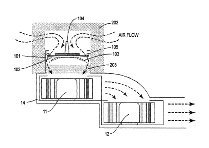
[0034] Figs. 6-8 are cut-away illustrations of dual centrifugal blower
system 10 with
various embodiments of air intake assemble 100 attached to axial inlet 15.
[0035] Fig. 6 illustrates a perspective view of an embodiment of air
intake assembly 100
with the check valve assembly attached to blower system 10. Check valve
assembly includes
frame 102, radial arms 106 flapper 103 and flapper connecting post 104
connected to flapper
103. Radial arms 106 are connected at one end to frame 102 and meet in the
center to form a
receptacle to accept flapper connecting post 104. In the embodiment shown in
Fig. 6, frame 102
is held in place via compression using 0-ring 105. The check valve assembly
prevents zero flow
conditions from getting back flow from fans and other process air, which at
high temperatures
can damage the solid oxide fuel cell (SOFC) and catalysts by oxidation.
Although the check
CA 03074863 2020-03-04
WO 2019/055472 PCT/US2018/050593
valve assembly is described and illustrated as a flapper type check valve,
other check valve
assemblies are contemplated, for example, a ball check valve, a spring and
piston check valve,
etc.
[0036] Flapper 103 can be a soft elastomer that induces very little
pressure drop to open
and uses the slight inherent stiffness and spring constant of the material to
close and seal. The
movement is illustrated in Fig. 8 wherein in its closed position, flapper 103
is shown as a solid
line, and in its open position, flapper 103 is shown as a dashed line. Flapper
103 opens when
blowers are engaged and pull air in through axial inlet 15. When blowers are
off or if the back
pressure of the system causes air to flow in the direction opposite the arrows
in Figs. 8A and 8B,
flapper 103 closes to prevent the flow of air.
[0037] Fig. 7 illustrates a perspective view of an embodiment of air
intake assembly 100
with the check valve assembly and a filter assembly or filtration unit
attached to blower system
10. The check valve assembly is the same as illustrated in Fig. 6 and
described above. The filter
assembly includes filter frame 201, filter 203, and 0-ring 205. Filter 203 is
held by filter frame
201. In the embodiment shown in Fig. 7, filter frame 201 is held in place via
compression using
0-ring 205. Filtration of the incoming air by the filter assembly after the
check valve assembly
can be used to filter particulates, volatile compounds, sulfur compounds,
hydrocarbons, etc.,
desiccants to reduce moisture, active filtration media to remove air
contaminants, etc. Filter 203
can be reticulated foam (low pressure drop) of some kind and potentially doped
with specific
materials to perform the tasks enumerated above, e.g. as a sulfur trap. The
particle size that is
filtered can range from 1-100 microns or beyond.
[0038] Although filter assembly is described having filter frame 201,
filter 203, and 0-
ring 205, other embodiments are contemplated. For example, a single form-
fitted foam can be
11
CA 03074863 2020-03-04
WO 2019/055472 PCT/US2018/050593
fitted into place without the need for filter frame 201 and 0-ring 205; Figs.
SA and 8B illustrate
these configurations.
100391 Figs. 8A and 8B illustrate perspective views of embodiments of air
intake
assembly 100 with the check valve assembly and multiple filter assemblies
attached to blower
system 10. Filtration of the incoming air before the check valve can be used
to filter particulates,
volatile compounds, and/or moisture.
100401 In the embodiment of Fig. 8A, an outer filter 202 is attached over
air intake
assembly 100. Outer filter 202 is tubular in shape with the filter material
extending across the
upper end; the bottom end is open and sized to receive air intake assembly
100. When outer filter
202 is fitted onto air intake casing 101, air can flow through the top and
partially along the sides
of outer filter 202.
100411 In the embodiment of Fig. 8B, outer filter 302 is attached over
air intake assembly
100 in a fashion similar to that of Fig. SA. Outer filter 302 is also tubular
in shape but in this
embodiment both the upper and lower ends are open. When outer filter 302 is
fitted onto air
intake casing 101, and positioned in an outer casing of a unit, for example a
fuel cell, the inner
surface of the casing 301 can be used to seal the upper open end of outer
filter 302. Air can then
flow only through and partially along the sides of outer filter 302.
[00421 It will, of course, be recognized that the invention is not
limited to blower units
possessing the forgoing characteristics but can utilize any centrifugal blower
unit having lesser
or greater dimensions, voltage and power requirements, impeller rpm, gas
pressure and gas flow
capabilities, etc.
[00431 Figs. 9A and 9B illustrate, respectively, a control system of a
centrifugal blower
12
CA 03074863 2020-03-04
WO 2019/055472 PCT/US2018/050593
system including an air intake assembly of the invention and a flow chart of
its control logic. As
those skilled in the art will recognize, these control operations can be
carried out by a suitably
programmed processor or controller.
100441 In addition to the individual control of the blower units, the
logic controller can
utilize inputs from the flow meter to monitor the components of the air intake
assembly. For
example, a very low flow exiting the radial outlet of the blower as measured
by the flow meter
can indicate one or more of the filter assemblies are preventing air flow
therethrough. Controller
can then output an alarm to indicate the low flow condition, or in turn begin
an emergency
shutdown procedure for the fuel cell to prevent damage thereof.
100451 The air intake assembly connected to the centrifugal blower system
of this
invention can manage gas flow requirements for a variety of applications.
Figs. 10A, 10B, 11A
and 11B illustrate the use of the air intake assembly of the blower system of
the invention to
provide and mediate gas flows in an SOFC assembly of the tubular type (Figs.
10A and 10B) and
planar type (Figs. 1 IA and 11B).
(00461 In tubular SOFC assembly, or stack, 140 of Figs. 10A and 10B,
first blower
system and air intake assembly 141 provides a gaseous fuel, e.g., hydrogen, to
manifold 142 for
distribution to the interior array 143 of tubular SOFC elements. Each tube in
array 143 can be of
known or conventional construction and, as shown in Fig. 10C, possesses an
innermost fuel-
contacting anode layer, intermediate electrolyte layer and outer cathode
layer. Second blower
system and air intake assembly 144 distributes air, initially at ambient
temperature, to manifold
145 from which it is released to provide a source of oxygen for the cathode
component of each
tubular SOFC element. The air entering manifold 145 gains heat from the hot
combustion gases
exiting tail burner 146 into heat exchanger 147. The dotted lines show the
flow path of the heated
13
CA 03074863 2020-03-04
WO 2019/055472 PCT/US2018/050593
air existing the outlets of manifold 145, passing through the SOFC array 143
and into tail burner
146 where it provides oxygen to support combustion of unspent fuel present in
the exhaust gas
emerging from the tubular SOFC elements into exhaust manifold 148 and from
there into the tail
burner. Finally, the hot combustion gases enter heat exchanger 147 where they
serve to preheat
incoming air provided by first blower system and air intake assembly 141 as
previously
indicated. Should back pressure initiate causing ambient air to begin to enter
the system back
through the tail burner and heat exchanger 147, check valve will close, thus
preventing the
ambient air from propagating further into the system.
[0047] The construction and operation of the planar SOFC assembly shown
in Figs. 11A
and 11B is much the same as that described above for the tubular SOFC assembly
of Figs. 10A
and 1013 the principal difference being the use of planar SOFC elements. As
shown in Fig. 11C,
each planar SOFC element in array 151 includes anode, electrolyte, cathode and
interconnect
components.
[0048] Although the invention has been described in detail for the
purpose of illustration,
it is understood that such detail is solely for that purpose, and variations
can be made therein by
those skilled in the art without departing from the spirit and scope of the
invention which is
defined in the claims.
14