Note: Descriptions are shown in the official language in which they were submitted.
CA 03075025 2020-03-05
WO 2019/050940 PCT/US2018/049535
METHODS FOR PROVIDING REFRIGERATION IN
NATURAL GAS LIQUIDS RECOVERY PLANTS
This applicant claims the benefit under 35 U.S.C. 119(e) of U.S. provisional
application Serial No. 62/544,633, filed September 6, 2017.
Background of the Invention
[0001]Natural gas is an important commodity throughout the world, as both an
energy
source and a source of raw materials. Worldwide natural gas consumption is
projected
to increase from 124 trillion cubic feet in 2015 to 177 trillion cubic feet in
2040 [U.S
Energy Information Administration, International Energy Outlook 2017
(1E02017)].
[0002]Natural gas is important not only as a source of energy but also as a
source of
feedstock for petrochemical manufacture. In general, natural gas is recovered
from
onshore and offshore oil and gas production wells. The major component of
natural gas
is typically methane. But, natural gas also contains amounts of other
hydrocarbons
such as ethane, propane, butanes, pentanes and heavier components. In addition
to
the hydrocarbon components, natural gas can also contain small amounts of
water,
hydrogen, nitrogen, helium, argon, hydrogen sulfide, carbon dioxide, and/or
mercaptans. For example, a typical natural gas may contain about 70 to 90
vol.%
methane, about 5 to 10 vol.% ethane, and the balance being propane, butanes,
pentanes, heavier hydrocarbons, and trace amounts of various other gases
(e.g.,
nitrogen, carbon dioxide, and hydrogen sulfide).
[0003]While natural gas is typically transported in high pressure transmission
pipelines,
natural gas is also commonly transported in liquefied form. In this case, the
natural gas
is first cryogenically liquefied and then the liquefied gas is transported via
cargo carriers
(e.g., trucks, trains, ships). However, liquefaction of natural gas can be
problematic
1_
CA 03075025 2020-03-05
WO 2019/050940 PCT/US2018/049535
since some components like the heavier hydrocarbons can form solids at
cryogenic
temperatures causing problems in equipment operation.
[0004] In natural gas processing the feedstream is typically treated to remove
impurities
such as carbon dioxide and sulfur compounds. But, in addition, the natural gas
can be
treated to reduce the level of heavier hydrocarbons to thereby avoid
solidification and
plugging of cryogenic heat exchange equipment. Further, the content of lighter
hydrocarbons such as C2, C3, and C4 may also be reduced during natural gas
processing in order to meet commercial requirements for the natural gas.
Moreover,
these lighter hydrocarbons are valuable feedstock materials. C2 is an
important
feedstock for petrochemical manufacture, C3 and C4 can be sold as LPG
(liquefied
petroleum gas) fuels, and C5+ hydrocarbons can be used for gasoline blending.
Natural gas liquids (NGL) recovery refers to the process of removing and
collecting
these lighter and heavier hydrocarbon products from natural gas.
[0005] Several known processes for liquefaction of natural gas and recovery of
C2+
hydrocarbons (NGL recovery) involve cryogenic expansion using a turbo-
expander. In
the Gas Subcooled Process (GSP) developed in the late 1970's, the natural gas
feed
stream after being cooled in a main heat exchanger is separated in a
gas/liquid
separator into a gas fraction and a liquid fraction. The liquid fraction is
expanded and
sent to the demethanizer (or deethanizer) column. The gas fraction is split
into two
streams. The first stream is expanded in a turbo-expander and fed to the
demethanizer
(or deethanizer). The second stream is further cooled by heat exchange with
the
overhead gas stream from the demethanizer (or deethanizer) and then introduced
into
the demethanizer (or deethanizer) as a ref lux stream. NGL product is removed
from the
bottom of the demethanizer (or deethanizer) and the overhead gas from the
demethanizer (or deethanizer) is removed as a residue gas product stream
containing
predominantly methane. See, for example, Campbell et al. (US 4,157,904).
[0006] A modification of the GSP process is the Recycle Split Vapor Process
(RSV). In
the RSV process a further ref lux stream for the demethanizer (or deethanizer)
column is
2
CA 03075025 2020-03-05
WO 2019/050940 PCT/US2018/049535
generated from the residue gas product stream. After being cooled by heat
exchange
with a portion of the gas fraction from the gas/liquid separator and by heat
exchange
with the natural gas feed stream, the residue gas product stream is
compressed. A
portion of the compressed residue gas is cooled by heat exchange with the
overhead
gas stream from the demethanizer (or deethanizer) column, expanded and
introduced
into the demethanizer (or deethanizer) column as reflux. See, for example,
Campbell et
at. (US 5,568,737).
[0007] Other processes for the recovery of natural gas liquids are known. For
example,
Buck (U.S. Pat. No. 4,617,039) describes a process wherein a natural gas feed
stream
is cooled, partially condensed, and then separated in a high-pressure
separator. The
liquid stream from the separator is warmed and fed into the bottom of a
distillation
(deethanizer) column. The vapor stream from the separator is expanded and
introduced
into a separator/absorber. Bottom liquid from the separator/absorber is used
as liquid
feed for the deethanizer column. The overhead stream from the deethanizer
column is
cooled and partially condensed by heat exchange with the vapor stream removed
from
the top of the separator/absorber. The partially condensed overhead stream
from the
deethanizer column is then introduced into the upper region of the
separatorlabsorber.
The vapor stream removed from the top of the separator/absorber can be further
warmed by heat exchange and compressed to provide a residue gas which, upon
further compression, can be reintroduced into a natural gas pipeline.
[0008] In such processes for the NGL recovery (e.g., recovery of ethane,
ethylene,
propane, propylene and heavier components), often there is a need for an
external
refrigeration system, such as a propane refrigeration unit, to achieve
temperatures
suitable for cryogenic separation. In such a process the main heat
exchanger(s) is/are
typically in fluid communication with the external refrigeration system.
[0009] There is a need for more efficient NGL recovery processes, particularly
processes which do not rely on an external refrigeration system and which can
provide
reduced energy consumption.
3
CA 03075025 2020-03-05
WO 2019/050940 PCT/US2018/049535
Summary of the Invention
[0010] The present invention provides for enhanced heat integration within a
natural
gas liquid (NGL) recovery plant to reduce the need for an external
refrigeration system
and thus reduce the number of pieces of equipment needed to operate the plant.
[0011] In a typical turbo-expander plant, a dry and treated (e.g., treated in
an amine
scrubbing unit for CO2 and/or sulfur compounds removal, a molecular sieve unit
or
glycol unit for dehydration, and/or a mercury absorbent guard bed for mercury
removal)
feed natural gas is cooled down in one or more heat exchangers by indirect
heat
exchange with one or more cold process streams, often augmented with external
refrigeration such as a propane refrigeration cycle. Such a typical NGL
recovery plant
is illustrated in Fig. 1.
[0012] The natural gas feed stream is cooled against process streams in a main
heat exchanger(s) which is typically formed from one or more brazed aluminum
heat
exchangers. The feed may also be cooled by a refrigerant (e.g., flowing in a
closed
loop refrigeration cycle such as a closed loop propane refrigeration cycle) in
one or
more shell and tube heat exchangers (chillers). Alternatively, the refrigerant
may pass
through one or more passages of the main brazed aluminum heat exchanger(s). By
this cooling, the feed stream is partially condensed and the partially
condensed feed
stream is then sent to an initial gas-liquid separation in a cold separator
vessel. From
the cold separator, the gas and liquid fractions are sent to a separation or
distillation
column for recovery of natural gas liquids (NGL) and a production of residue
gas
product stream containing predominantly methane.
[0013] In the plant and method according to the invention, an external
refrigerant system
such as a closed loop propane refrigeration cycle is not required (and
preferably is not
4
CA 03075025 2020-03-05
WO 2019/050940 PCT/US2018/049535
used) for cooling the natural gas feed stream. Instead, a portion of the
residue gas
stream produced by the plant is expanded and then used as a cooling medium in
the
main heat exchanger(s) and also used as a cooling medium in a heat exchanger
for
cooling ref lux stream(s) used in the separation or distillation column.
[00141 Therefore, a process embodiment according to the invention for NGL
recovery
comprises:
introducing a natural gas feed stream into a main heat exchanger(s) wherein
the
feed stream is cooled and partially condensed,
introducing the partially condensed feed stream into a cold gas/liquid
separator
wherein the partially condensed feed stream is separated into a liquid
fraction and a
gaseous fraction,
introducing the liquid fraction into a separation or distillation column
system,
separating the gaseous fraction into a first portion and a second portion,
cooling the first portion of the gaseous fraction in an overhead heat
exchanger by
indirect heat exchange with an overhead gaseous stream removed from the top of
the
separation or distillation column system, and introducing the cooled and
partially
condensed first portion of the gaseous fraction into the separation or
distillation column
system,
expanding the second portion of the gaseous fraction and introducing the
expanded second portion of the gaseous fraction into the separation or
distillation
column at,
removing a C2+ or C3+ liquid product stream (NGL) from the bottom of the
separation or distillation column system,
removing the overhead gaseous stream from the top of the separation or
distillation column system, the overhead gaseous stream being enriched with
methane,
using the overhead gaseous stream as a cooling medium in the overhead heat
exchanger and in the main heat exchanger(s),
compressing the overhead gaseous stream in a residue gas compression unit to
obtain a pressurized residue gas stream,
CA 03075025 2020-03-05
WO 2019/050940 PCT/US2018/049535
expanding a portion of the pressurized residue gas stream and using the
expanded residue gas as a cooling medium in the overhead heat exchanger and in
the
main heat exchanger(s), and
compressing the expanded residue gas used as a cooling medium to form a
compressed residue gas stream and then combining the compressed residue gas
stream with the overhead gaseous stream upstream of the residue gas
compression
unit.
[0015] In accordance with one aspect of the above process embodiment, the
separation or distillation column system contains one column that acts as a
demethanizer column or a deethanizer column. In accordance with another aspect
of
the above embodiment, the separation or distillation column system contains
two
columns that together act as a demethanizer column or a deethanizer column.
[0016] Another process embodiment according to the invention for NGL recovery
comprises:
introducing a natural gas feed stream into a main heat exchanger(s) wherein
the
feed stream is cooled and partially condensed,
introducing the partially condensed feed stream into a cold gas/liquid
separator
wherein the partially condensed feed stream is separated into a liquid
fraction and a
gaseous fraction,
introducing the liquid fraction into a separation or distillation column,
separating the gaseous fraction into a first portion and a second portion,
cooling the first portion of the gaseous fraction in an overhead heat
exchanger by
indirect heat exchange with an overhead gaseous stream removed from the top of
the
separation or distillation column, and introducing the cooled and partially
condensed
first portion of the gaseous fraction into the separation or distillation
column at a point
above the introduction point of the liquid fraction into the separation or
distillation
column,
expanding the second portion of the gaseous fraction and introducing the
expanded second portion of the gaseous fraction into the separation or
distillation
6
CA 03075025 2020-03-05
WO 2019/050940 PCT/US2018/049535
column at a point above the introduction point of the liquid fraction into the
separation or
distillation column,
removing a C2+ or C3+ liquid product stream (NGL) from the bottom of the
separation or distillation column,
removing the overhead gaseous stream from the top of the separation or
distillation column, the overhead gaseous stream being enriched with methane,
using the overhead gaseous stream as a cooling medium in the overhead heat
exchanger and in the main heat exchanger(s),
compressing the overhead gaseous stream in a residue gas compression unit to
obtain a pressurized residue gas stream,
expanding a portion of the pressurized residue gas stream and using the
expanded residue gas as a cooling medium in the overhead heat exchanger and in
the
main heat exchanger(s), and
compressing the expanded residue gas used as a cooling medium to form a
compressed residue gas stream and then combining the compressed residue gas
stream with the overhead gaseous stream upstream of the residue gas
compression
unit.
[0017]Additionally, an apparatus embodiment according to the invention for NGL
recovery comprises:
a main heat exchanger(s) for cooling and partially condensing a natural gas
feed
stream,
a separation or distillation column system for separating the natural gas feed
stream into a C2+ or C3+ liquid product stream and an overhead gaseous stream
enriched in methane,
a cold gas/liquid separator wherein the partially condensed feed stream is
separated into a liquid fraction and a gaseous fraction,
a pipeline for removing the liquid fraction from the bottom of the cold
gas/liquid
separator and introducing the liquid fraction into the separation or
distillation column
system,
7
CA 03075025 2020-03-05
WO 2019/050940 PCT/US2018/049535
means (e.g., pipe branching) for separating the gaseous fraction into a first
portion and a second portion,
an overhead heat exchanger for cooling the first portion of the gaseous
fraction
by indirect heat exchange with an overhead gaseous stream removed from the top
of
the separation or distillation column system,
a pipeline for removing the cooled first portion of the gaseous fraction from
the
overhead heat exchanger and introducing the cooled first portion into the
separation or
distillation column system,
means for expanding (e.g., a turbo-expander) the second portion of the gaseous
fraction,
a pipeline for removing the expanded first portion of the gaseous fraction
from
the means for expanding and introducing the expanded second portion of the
gaseous
fraction into the separation or distillation column system,
a bottom outlet for removing the C2+ or C3+ liquid product stream (NGL) from
the bottom of the separation or distillation column system,
a top outlet for removing the overhead gaseous stream from the top of the
separation or distillation column,
a residue gas compression unit for compressing the overhead gaseous stream to
obtain a pressurized residue gas stream,
means for expanding (e.g., a turbo-expander) a portion of the pressurized
residue gas stream to form an expanded residue gas stream,
a pipeline for removing the expanded residue gas stream from the means for
expanding and introducing the expanded residue gas stream into the overhead
heat
exchanger as a cooling medium,
a pipeline for removing the expanded residue gas stream from the overhead heat
exchanger and introducing the expanded residue gas stream into the main heat
exchanger as a cooling medium, and
means for compressing (e.g., a single or multistage compressor) the expanded
residue gas to form a compressed residue gas stream and means for combining
the
compressed residue gas stream with the overhead gaseous stream upstream of the
residue gas compression unit.
8
CA 03075025 2020-03-05
WO 2019/050940 PCT/US2018/049535
[0018] In accordance with one aspect of the above apparatus embodiment, the
separation or distillation column system contains one column that acts as a
demethanizer column or a deethanizer column. In accordance with another aspect
of
the above embodiment, the separation or distillation column system contains
two
columns that together act as a demethanizer column or a deethanizer column.
[0019] Another apparatus embodiment according to the invention for NGL
recovery
comprises:
a main heat exchanger(s) for cooling and partially condensing a natural gas
feed
stream,
a separation or distillation column for separating the natural gas feed stream
into
a 02+ or 03+ liquid product stream and an overhead gaseous stream enriched in
methane,
a cold gas/liquid separator wherein the partially condensed feed stream is
separated into a liquid fraction and a gaseous fraction,
a pipeline for removing the liquid fraction from the bottom of the cold
gas/liquid
separator and introducing the liquid fraction into the separation or
distillation column,
means (e.g., pipe branching) for separating the gaseous fraction into a first
portion and a second portion,
an overhead heat exchanger for cooling the first portion of the gaseous
fraction
by indirect heat exchange with an overhead gaseous stream removed from the top
of
the separation or distillation column,
a pipeline for removing the cooled first portion of the gaseous fraction from
the
overhead heat exchanger and introducing the cooled first portion into the
separation or
distillation column at a point above the introduction point of the liquid
fraction into the
separation or distillation column,
means for expanding (e.g., a turbo-expander) the second portion of the gaseous
fraction,
a pipeline for removing the expanded first portion of the gaseous fraction
from
the means for expanding and introducing the expanded second portion of the
gaseous
9
CA 03075025 2020-03-05
WO 2019/050940 PCT/US2018/049535
fraction into the separation or distillation column at a point above the
introduction point
of the liquid fraction into the separation or distillation column,
a bottom outlet for removing the C2+ or C3+ liquid product stream (NGL) from
the bottom of the separation or distillation column,
a top outlet for removing the overhead gaseous stream from the top of the
separation or distillation column,
a residue gas compression unit for compressing the overhead gaseous stream to
obtain a pressurized residue gas stream,
means for expanding (e.g., a turbo-expander) a portion of the pressurized
residue gas stream to form an expanded residue gas stream,
a pipeline for removing the expanded residue gas stream from the means for
expanding and introducing the expanded residue gas stream into the overhead
heat
exchanger as a cooling medium,
a pipeline for removing the expanded residue gas stream from the overhead heat
exchanger and introducing the expanded residue gas stream into the main heat
exchanger as a cooling medium, and
means for compressing (e.g., a single or multistage compressor) the expanded
residue gas to form a compressed residue gas stream and means for combining
the
compressed residue gas stream with the overhead gaseous stream upstream of the
residue gas compression unit.
Brief Description of the Drawings
[00201The invention as well as further advantages, features and examples of
the
present invention are explained in more detail by the following descriptions
of
embodiments based on the Figures (in which like reference numerals are used to
identify corresponding or analogous elements), wherein:
[00211Figure 1 is a schematic representation of a typical natural gas liquids
recovery
plant;
CA 03075025 2020-03-05
WO 2019/050940 PCT/US2018/049535
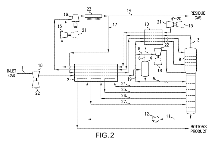
[0022] Figure 2 is a schematic representation of a natural gas liquids
recovery plant
according to the invention for recovery of ethane and heavier components;
[0023] Figure 3 is a schematic representation of an alternative natural gas
liquids
recovery plant according to the invention for recovery of ethane, propane and
heavier
components;
[0024] Figure 4 is a schematic representation of an alternative natural gas
liquids
recovery plant according to the invention for recovery of propane and heavier
components; and
[0025] Figure 5 is a schematic representation of a modification of the NGL
recovery
plant according to the invention wherein a single column of the distillation
system is
replaced by two columns.
Detailed Description of the Invention
[0026]The present invention provides for the addition of an expansion unit
such as a
turbo-expander within a natural gas liquids recovery process or plant to allow
for high
pressure product gas (residue gas) to be used as a refrigerant to provide the
necessary
refrigeration to either of these operations.
[0027]The additional turbo-expander takes the high-pressure residue gas which
is a
methane-enriched or methane- and ethane- enriched gas from the discharge of
the
product pipeline recompression equipment (residue gas compression unit) and
expands, for example, in a turbo-expander, the gas down to a pressure of
between, for
example, 100 and 300 psig. The resultant cold refrigerant gas then passes
through the
overhead heat exchanger and the main heat exchanger(s) and then preferably
utilizes
the energy from the expansion of the residue gas to boost the pressure of the
resultant
11
CA 03075025 2020-03-05
WO 2019/050940 PCT/US2018/049535
heated refrigerant gas back to the inlet of the product pipeline recompression
equipment.
[0028]The advantages of this invention are several fold. First, elimination of
an external
refrigeration unit (such as a closed loop propane refrigeration system) can
increase
process efficiency over other NGL plant configurations such as GSP, RSV, and
CryoPlus. The total horse power for the plant (residue and refrigerant)
required for
operation is on the order of 5 to 20 vol.% less than such other NGL plant
configurations
that utilize an external refrigeration system such as a closed loop propane
refrigeration
system.
[00291The higher efficiency is due in part to ability to use equipment with
higher
efficiencies. Refrigeration loop compressors (generally oil-flooded screw
compressors)
are usually 65-75% efficient whereas the residue gas compressors are generally
80-
85% efficient and can go as high as 90% efficient. An expander, such as the
expander
used to expand a portion of the residue gas which is then employed as
refrigerant, is
around -85% efficient and a compressor coupled to such an expander is -75%
efficient.
[0030]Additionally, the heat exchange in the main heat exchanger(s) is more
efficient because the maximum temperature difference between the cooling and
heating curves is low. The maximum temperature difference between the cooling
and heating curves of the residue gas exchanged with the feed gas can be as
low
as 152 F. Conversely, for a heat exchange between a propane refrigerant and a
feed gas the maximum temperature difference between the cooling and heating
curves of the refrigerant exchanged with the feed gas is usually around 40', F
or
higher,
[0031]In the process, according to the invention, utilizing only residue gas
compression
as the source of both residue gas product compression and refrigerant
compression
offers an added amount of flexibility with regards to plant operation over
existing
technology. The operating company can either use the residue compression to
12
CA 03075025 2020-03-05
WO 2019/050940 PCT/US2018/049535
compress more residue gas product to be fed out of the plant to be sold, or
can instead
recycle more of the high-pressure residue gas as the refrigerant to increase
the level of
cooling in the plant and thus, achieve a higher recovery level of NGL
products.
[0032] The process/plant, according to the invention, also permits the main
heat
exchanger(s), typically brazed aluminum heat exchanger(s), to operate under
lower
thermal stress. At any given point within an exchanger, the difference in the
temperature between the hot fluid(s) and cold fluid(s) can cause thermal
stresses within
the exchanger. Long duration or short duration thermal stress can affect the
exchanger
life, with lower stresses extending the life of the equipment. The maximum
allowable
difference in temperature is typically 500 F based on exchanger manufacturer
constraints and most processes, such as the process shown in FIG 1, are
performance
limited by this constraint in operation and design due in part to the use of a
closed loop
propane refrigeration system. Since propane boils at one temperature
(typically -20 to -
30 F) at a given pressure and the plant feed gas condenses over a range of
temperatures (typically 100 to -50 F), the use of propane as a refrigerant is
limited in a
single exchanger because the thermal stresses can become high due to the high
temperature difference between the fluids.
[0033] These lower temperature differences permitted by the inventive
process/plant
will increase the life of the brazed aluminum heat exchangers as they will be
less
prone to failure due to temperature stress fractures and cracking.
[0034] Another advantage of the process/plant according to the invention is
the
elimination of contamination of the refrigerant with lube oil. Generally, oil-
flooded screw
compressors are used in typical propane refrigeration systems. This means the
refrigerant is in intimate contact with the compressor lube oil and thus the
refrigerant
carries some lube oil out of the compressor and into the heat exchanger
equipment.
The entrained lube oil can lead to fouling issues in the exchanger equipment
and/or loss
of heat transfer area and ultimately loss of performance. With the elimination
of the
closed loop propane refrigeration unit, the issues associated with lube oil in
the
13
CA 03075025 2020-03-05
WO 2019/050940 PCT/US2018/049535
refrigerant system are also eliminated. This also reduces the required
maintenance
knowledge for the operator as the only compression used is residue
compression, as
opposed to residue compression and refrigerant compression.
[0035] In addition, since the process/plant, according to the invention, does
not require
an external refrigeration system, there is a substantial savings in terms of
the required
footprint (plot space) for the plant. Instead of the external refrigeration
system, the plant
refrigeration system can operate with a single additional turbo-expander for
expanding
the portion of the residue gas substream that is to be used for cooling and
preferably an
after cooler (e.g., an air-cooler) downstream of the residue gas compression
unit for
cooling the compressed residue gas.
[00361A further advantage is that, since the process/plant, according to the
invention,
does not require an external refrigeration system, there is no need to store
or buy
process refrigerant.
[0037] In one embodiment of the process and apparatus according to the
invention the
separation or distillation column operates as a demethanizer separating the
feed stream
into an overhead gaseous stream enriched in methane and lower boiling
components
and a bottom liquid stream enriched in ethane and higher boiling components.
In
another embodiment of the process and apparatus according to the invention the
separation or distillation column operates as a deethanizer separating the
feed stream
into an overhead gaseous stream enriched in methane, ethane and lower boiling
components and a bottom liquid stream enriched in propane and higher boiling
components.
[0038] The separation or distillation column contains one or more contact or
separation
stages such as trays and/or packing to provide the necessary contact and
enhance
mass transfer between the rising vapor stream and the downward flowing liquid
stream.
Such trays and packings are well known in the art.
14
CA 03075025 2020-03-05
WO 2019/050940 PCT/US2018/049535
[0039] According to one embodiment of the invention, the liquid fraction from
the cold
gas/liquid separator is expanded via an expansion valve and then introduced
into a
lower region of the separation or distillation column. According to another
embodiment
of the invention, the liquid fraction from the cold gas/liquid separator is
first expanded
via an expansion valve and introduced into the main heat exchanger, where it
acts as a
cooling medium, before being introduced into a lower region of the separation
or
distillation column.
[00401 According to another embodiment of the invention, the liquid fraction
from the
cold gas/liquid separator is split into two substreams. One of the substreams
is
expanded via an expansion valve and then introduced into a lower region of the
separation or distillation column. The other substream is combined with the
first portion
of the gaseous fraction from the cold gas/liquid separator. The resultant
combined
stream is cooled in the overhead heat exchanger by heat exchange with the
overhead
gaseous stream removed from the top of the separation or distillation column.
The
combined stream is then expanded via an expansion valve and introducing into
the
upper region of the separation or distillation column.
[0041] In one embodiment of the invention, a portion of the compressed residue
gas is
sent directly to a turbo-expander and the resultant expanded residue gas
portion is
used as a cooling medium in the overhead heat exchanger and then in the main
heat
exchanger before being compressed and combined with the overhead gaseous
stream
removed from the top of separation or distillation column. In a further
embodiment the
portion of the compressed residue gas is first cooled in the main heat
exchanger and
then is sent to a turbo-expander. In each of these embodiments the resultant
expanded residue gas portion is used as a cooling medium in the overhead heat
exchanger and then in the main heat exchanger before being compressed and
combined with the overhead gaseous stream removed from the top of separation
or
distillation column.
CA 03075025 2020-03-05
WO 2019/050940 PCT/US2018/049535
[0042] In a further embodiment, a further portion of the compressed residue
gas is
cooled in the main heat exchanger and the overhead heat exchanger, expanded in
an
expansion valve, and introduced into the upper region of the separation or
distillation
column as a ref lux stream.
[0043] Figure 1 illustrates a typical (RSV Design) plant for cryogenic
recovery of natural
gas liquids. The feed stream 1 of natural gas, typically pretreated to remove
water and
optionally CO2 and /or H2S, is introduced into the system at a temperature of,
for
example, 40 to 120 QF and a pressure of 500 to 1100 psig. The natural gas feed
stream is cooled in a main heat exchanger 2 by indirect heat exchange with
process
streams to a temperature -50 to 40 F, and then is further cooled by in a
secondary
heat exchanger 3 by indirect heat exchange with a refrigerant (e.g., propane)
from a
closed loop refrigeration cycle. Thereafter, the cooled natural gas feed
stream 1 can
then be further cooled in the main heat exchanger 2 and then sent to a cold
gas-liquid
separator 4 where the cooled and partially condensed feed stream 1 is
separated into
a liquid fraction 5 and a gaseous fraction 6.
[0044] The liquid fraction 5 is introduced into a lower region of a separation
or
distillation column 9 which is a demethanizer, i.e., separates the feed stream
into a
gaseous overhead stream containing predominantly methane and a liquid bottom
stream containing ethane and heavier components, i.e., the NGL product stream.
Alternatively, column 9 can be a deethanizer separating the feed stream into a
gaseous overhead stream containing predominantly methane plus ethane and a
liquid
bottom stream containing propane and heavier components (NGL product). The
operating pressure of column 9 (i.e., the pressure in the upper region) is,
for example,
150 to 450 psig.
[0045] The gaseous fraction 6 from separator 4 is split into a first gas
substream 7 and
a second gas substream 8. The first gas substream 7 is expanded to a pressure
of,
for example, 150 to 450 psig, and then introduced into the separation or
distillation
column 9 at a midpoint, thereof. The second gas substream 8 is cooled by
indirect
16
CA 03075025 2020-03-05
WO 2019/050940 PCT/US2018/049535
heat exchange in an overhead heat exchanger 10 to a temperature of -160 to -75
9F,
expanded via an expansion valve, and then introduced into an upper region of
separation or distillation column 9 (demethanizer or deethanizer) as a reflux
stream.
[0046] Optionally, before the liquid fraction 5 is introduced into a lower
region of a
column 9, a substream 19 of the liquid fraction is branched off and combined
with the
second gas substream 8 and then the combined stream is cooled by indirect heat
exchange in the overhead heat exchanger 10, expanded via an expansion valve,
and
introduced into an upper region of separation or distillation column 9.
[0047]To generate a rising vapor stream within the separation or distillation
column 9,
a reboiler stream 24 is removed from the lower region of column 9 and used as
a
cooling heat exchange medium in main heat exchanger 2. The resultant heated
stream 25 is returned to the lower region of column 9 at a point below where
stream 24
is removed. Additionally, a further reboiler stream 26 can be removed from the
lower
region of column 9, at a point below the point where stream 25 is returned to
the lower
region and used as a further cooling heat exchange medium in main heat
exchanger 2.
The resultant heated stream 27 is returned to the lower region of column 9 at
a point
below where stream 26 is removed.
[00481A liquid product stream 11 of NGL (C2+ product or C3+ product) is
removed
from the bottom of column 9. The pressure of the liquid product stream is
increased to,
for example, 300 to 700 psig, by NGL booster pump 12. The elevated pressure
liquid
product stream 11 is then used as a cooling medium in main heat exchanger 2
before
being removed from the system at, for example, a temperature of 40 to 115 QF
and a
pressure of 300 to 700 psig.
[0049] The overhead gaseous stream 13 is removed from the top of separation or
distillation column 9 at a pressure of 150 to 450 psig and a temperature of,
for
example, -165 to -70 QF and is heated by indirect heat exchange in overhead
heat
17
CA 03075025 2020-03-05
WO 2019/050940 PCT/US2018/049535
exchanger 10 and then further heated by indirect heat exchange in main heat
exchanger 2.
[00501This overhead gaseous stream 13 is characterized as a residue gas and
contains a significant amount of methane. If column 9 is a deethanizer, this
stream will
also contain an appreciable amount of ethane. After being used as a cooling
medium
in overhead heat exchanger 10 and main heat exchanger 2, overhead gaseous
stream
13 is subjected to compression in one or more compressors 18, 16 (or one or
more
multistage compressors), cooled in an after cooler 23 (e.g., an air-cooler)
and then
discharged from the system as a compressed residue gas stream 14 at, for
example, a
temperature of 60 to 120 QF and a pressure of 900 to 1440 psig. A substream 17
is
branched off from residue gas stream 14, cooled in main heat exchanger 2, and
further
cooled in overhead heat exchanger 10 before being returned to the upper region
of
column 9 as a reflux stream.
[00511Turning then to Fig. 2, this figure represents a schematic diagram of a
natural
gas liquids recovery plant according to the present invention. Unlike the
plant shown
in Fig. 1, this embodiment does not have a secondary heat exchanger 3 wherein
the
feed stream is cooled by indirect heat exchange with a refrigerant from a
closed loop
refrigeration cycle. Instead, this embodiment uses a portion of the residue
gas
generated from the gaseous overhead stream 13 removed from the top of column 9
to
provide cooling, as discussed further below.
[0052] The natural gas feed stream 1, pretreated to remove water, CO2 and/or
H2S,
contains, for example, 45 to 95 vol.% Cl, 3 to 25 vol.% C2, 2 to 20 vol.% C3,
0.5 to 7
vol.% C4, 0.1 to 8 vol.% C5, and 0 to 5 vol.% C6 and heavier hydrocarbons. As
a
specific example, the dry feed gas has a composition of 2.4 vol.% nitrogen,
71.0 vol.%
Cl (methane), 13.7vo1. /0 C2 (ethane), 8.1 vol.% C3 (propane), 0.9 vol.% iC4
(isobutane, 2.3 vol.c/0 nC4 (normal butane), 0.3 vol. /0 iC5 (isopentane), 0.5
vol.% nC5
(normal pentane) and 0.6 vol.% C6 (hexanes) and heavier hydrocarbons, and has
a
pressure of 500 to 1100 psig and a temperature of 40 to 120 F. The dry feed
gas
18
CA 03075025 2020-03-05
WO 2019/050940 PCT/US2018/049535
stream 1 is compressed in feed compressor 18 to a pressure of 700 to 1400
psig,
preferably 900 to 1250 psig, and then introduced into main heat exchanger 2
(which is
typically formed from one or more brazed aluminum heat exchangers) where it is
cooled (and partially condensed) to a temperature of -10 to 20 F, preferably
0 to 10 2F.
The resultant cooled partially condensed feed gas is then fed to a cold
gas/liquid
separator 4.
[00531 In cold gas/liquid separator 4 the cooled and partially condensed feed
gas is
separated into liquid fraction 5 and gaseous fraction 6. The liquid fraction 5
is
expanded through an expansion valve to a pressure of, for example, 150 to 450
psig,
preferably 200 to 330 psig and to a temperature of, for example, -10 to -50
QF,
preferably -15 to -30 2F before being introduced into a lower region of
separation or
distillation column 9. Stream 5 is introduced at a point below the point which
the
column diameter increases and also above the lowest liquid/vapor contact means
in
the column. In this embodiment, column 9 operates as a demethanizer.
[00541The gaseous fraction 6 from separator 4 is split into first gas
substream 7 and
second gas substream 8. First gas substream 7 is expanded in a turbo-expander
22
to a pressure of, for example, 150 to 450 psig, preferably 200 to 330ps1g,
which
reduces the temperature of the substream to a temperature of, for example, -30
to -110
2F, preferably -60 to -90 2F. Substream 7 is then introduced into column 9 at
a
midpoint thereof (i.e., at a point above the introduction point of stream 5).
The second
gas substream 8 is cooled by indirect heat exchange in overhead heat exchanger
10 to
a temperature of, for example, -65 to -150 F, preferably -80 to -145 2F at
high
pressure. Substream 8 is then expanded through an expansion valve to a
pressure of,
for example, 150 to 450 psig, preferably 200 to 330 psig and to a temperature
of, for
example, -110 to -150 F, preferably -120 to -145 2F before being introduced
into an
upper region of column 9 as a ref lux stream. Preferably, the turbo-expander
22 is
coupled to feed compressor 18. The operating pressure of column 9 (i.e., the
pressure
in the upper region) is, for example, 200 to 330 psig.
19
CA 03075025 2020-03-05
WO 2019/050940 PCT/US2018/049535
[0055] In general, the operating pressures and temperatures for column 9 are
lower
when the column functions as a demethanizer in comparison to when the column
functions as a deethanizer. For example, the operating pressure of the
demethanizer
column is preferably between 200 and 330 psig, and the operating pressure of
the
deethanizer column is preferably between 300 to 450 psig, depending on the
composition of the gas and separation level
[0056] Before liquid fraction 5 is introduced into column 9, a substream 19 of
the liquid
fraction is optionally branched off and combined with the second gas substream
8.
The combined stream is then cooled by indirect heat exchange in the overhead
heat
exchanger 10 before being expanded and introduced into an upper region of
column 9.
[0057] To generate a rising vapor stream within the separation or distillation
column 9,
reboiler stream 24 can be removed from the lower region of column 9 at a
temperature
of, for example, -10 to 20 2F, preferably 0 to 10 2F, and used as a cooling
heat
exchange medium in main heat exchanger 2. The resultant heated stream 25 is
returned to the lower region of column 9 at a point below where stream 24 is
removed.
Additionally, a further reboiler stream 26 can be removed from the lower
region of
column 9, at a point below the point where stream 25 is returned to the lower
region
and at a temperature of 25 to 50 2F, preferably 30 to 40 2F, and used as a
further
cooling heat exchange medium in main heat exchanger 2. The resultant heated
stream 27 is returned to the lower region of column 9 at a point below where
stream 26
is removed.
[0058] Liquid product stream 11 of NGL (C2+ product) is removed from the
bottom of
column 9. This stream is an ethane-enriched stream having a higher
concentration of
ethane than that of the feed stream 1. The pressure of stream 11 is increased
by NGL
booster pump 12 to a pressure of, for example, 300 to 700 psig, preferably 600
to 650
psig. The elevated pressure liquid product stream 11 is then used as a cooling
medium in main heat exchanger 2 before being removed from the system at, for
CA 03075025 2020-03-05
WO 2019/050940 PCT/US2018/049535
example, a temperature of 40 to 115 2F and a pressure of 300 to 700 psig (if
desired,
this pressure can be further increased to a pipeline pressure of 400 to 1400
psig using
additional pumps). The NGL liquid product stream (C2+ product) has a
composition of,
for example, 0 to 2 vol.% Cl, 30 to 60 vol.% C2, 20 to 40 vol.% C3, 5 to 15
vol.% C4, 1
to 5 vol. /0 C5, and 1 to 5 vol.% C6 and heavier hydrocarbons. For example,
the NGL
product stream can contain 0.8 vol.% Cl, 50.5 vol.% C2, 30.5 vol.% C3, 3.4
vol.c/0 iC4,
8.9 vol.% nC4, 1.7 vol.% iC5, 1.9 vol.% nC5 and 2.3 vol.% C6 and heavier
hydrocarbons.
[0059] Overhead gaseous stream 13 is removed from the top of separation column
9 at
a pressure of, for example, 150 to 450 psig, preferably 200 to 330 psig, and a
temperature of, for example, -80 to -170 F, preferably -100 to -165 F. This
stream is
a methane-enriched stream having a higher concentration of methane than that
of the
feed stream 1. Overhead gaseous stream 13 is then heated by indirect heat
exchange
in overhead heat exchanger 10 to temperature of, for example, -20 to 10 F,
preferably
-5 to 5 F, and then further heated by indirect heat exchange in main heat
exchanger 2
to a temperature of, for example, 90 to 115 F, preferably 105 to 110 F. This
residue
gas stream 13 is then fed to a residue gas compression unit 16 containing one
or more
compressors, where it is compressed to a pressure of, for example, 900 to 1440
psig,
preferably 1000 to 1200 psig. The compressed residue gas is then cooled in an
after
cooler 23 (e.g., an air cooler), and recovered as a residue sales gas having a
composition of, for example, 90 to 99 vol.% Cl and 0.5 to 15 vol.% C2. For
example,
the residue sales gas has a composition of 3.3 vol.% nitrogen, 96.2 vol.% Cl
and 0.5
vol.% C2, a pressure of 900 to 1440 psig, and a temperature of 60 to 120 F.
POW After compression in residue gas compression unit 16, a first substream 17
is
branched off from the compressed residue gas stream 14 and cooled in main heat
exchanger 2 to a temperature of, for example, 10 to 30 2F, preferably 15 to 25
2F.
Substream 17 is then further cooled in overhead heat exchanger 10 to a
temperature
of, for example, -145 to -165 F, preferably -155 to -160 2F. Substream 17 is
then
expanded through an expansion valve to a pressure, for example, 150 to 450
psig,
21
CA 03075025 2020-03-05
WO 2019/050940 PCT/US2018/049535
preferably 200 to 330 psig and to a temperature -150 to -170 2F, preferably -
155 to -
165 2F before being fed to the upper region of column 9 as a ref lux stream.
[00611To provide further cooling, after compression in residue gas compression
unit 16
(and after cooler 23), a second substream 20 of the compressed residue gas
stream 14
is expanded in a turbo-expander 21 (or perhaps two or more small expanders) to
a
pressure of, for example, 100 to 300 psig, preferably 140 to 200 psig, and a
temperature of, for example, -65 to -100 F, preferably -75 to -95 F.
Substream 20 is
then used as a cooling medium, first in overhead heat exchanger 10 and then in
main
heat exchanger 2, before being compressed in compressor 15 to a pressure of,
for
example, 250 to 400 psig, preferably 300 to 380 psig. The resultant compressed
substream 20, after preferably being cooled in an after cooler (not shown) is
then
combined with the residue gas stream 13 removed from the top of column 9, and
then
the combined stream is sent to residue compression unit 16. Preferably, the
turbo-
expander 21 is coupled to compressor 15.
[0062] In a modification of the embodiment of Fig. 2 (not shown in the
Figure), a heat
exchanger can be used (e.g., a shell and tube heat exchanger) to provide heat
exchange between the residue gas discharged from compressor 15 (before it is
introduced into residue gas compression unit 16) and the expanded residue gas
portion
discharged from expander 21 (before it is introduced into the overhead heat
exchanger
10). This modification (which can also be made in the embodiments of Figs. 3
and 4)
allows for greater flexibility with regards to adjusting the duty of the
refrigerant.
[0063] Figure 3 is a schematic representation of a further embodiment of a
natural gas
liquids recovery plant according to the invention. This embodiment is similar
to the
embodiment of Fig. 2. The embodiment of Fig. 3 differs from that of Fig. 2
with regards to
the generation and handling of the second substream 20 of the compressed
residue gas
14. In this embodiment, column 9 operates as a demethanizer. The operating
pressure of column 9 (i.e., the pressure in the upper region) is, for example,
150 to 450
psig, preferably 200 to 330 psig.
22
CA 03075025 2020-03-05
WO 2019/050940 PCT/US2018/049535
[0064] In Fig. 3, after compression in residue gas compression unit 16 and
cooling in
after cooler 23, the second substream 20 of the compressed residue gas stream
14 is
branched off and cooled in the main heat exchanger 2. Second substream 20,
before
being expanded in turbo-expander 21, is used as a heating medium in main heat
exchanger 2 where it is cooled to a temperature of, for example. -20 to 40
c2F,
preferably to 5 to 20 F. Second substream 20 is then expanded in turbo-
expander 21
(or perhaps two or more small expanders) to a pressure of, for example, 100 to
300
psig, preferably 140 to 200 psig and a temperature of, for example, -130 to -
170 F.
preferably -150 to -165 9F; and then used as a cooling medium, first in
overhead heat
exchanger 10 and then in main heat exchanger 2. Substream 20 is then
compressed in
compressor 15, cooled in an after cooler (not shown; e.g., an air-cooler)
combined with
the residue gas stream 13 removed from the top of column 9, and then the
combined
stream is sent to residue compression unit 16. Here again, turbo-expander 21
is
preferably coupled to compressor 15.
[0065] Fig. 4 is a schematic representation of a further embodiment of a
natural gas
liquids recovery plant according to the invention. This embodiment is similar
to the
embodiment of Fig. 2. However, in the embodiment of Fig. 4 the separation or
distillation
column 9 is a deethanizer and the handling of the liquid fraction 5 from cold
gas/liquid
separator 4 and the heating of the column 9 differs from that of Fig. 2. The
operating
pressure of column 9 (i.e., the pressure in the upper region) is, for example,
150 to 450
psig, preferably 300 to 400 psig. The liquid product stream 11 of NGL removed
from
the bottom of column 9 is a 03+ liquid stream. This stream is a propane-
enriched
stream having a higher concentration of propane than that of the feed stream
1. The
gaseous overhead stream 13 removed from the top of separation column 9 is a 02-
stream. This stream is a methane-enriched and ethane-enriched stream having
higher
concentration of methane and ethane than that of the feed stream 1.
[0066] In Fig. 4, liquid fraction 5 is first expanded via an expansion valve
to a pressure
of, for example, 150 to 400 psig preferably 300 to 400 psig. Liquid fraction 5
is then
23
CA 03075025 2020-03-05
WO 2019/050940 PCT/US2018/049535
heated in the main heat exchanger 2 to a temperature of, for example, 60 to
120 F,
preferably 90 to 115 F, before being introduced into the lower region of
column 9. In
addition, the embodiment of Fig. 4 does not use reboiler streams 24 ¨ 27 to
generate
the rising vapor stream within the separation or distillation column 9.
Instead, a liquid
stream is removed from the bottom region of column 9, heated in a reboiler
heat
exchanger by indirect heat exchange with an external heating medium and then
returned to the bottom region of column 9.
[0067] Fig. 5 illustrates a modification that can be applied to each of the
embodiments of
Figs. 2-4. In this modification the single demethanizer or deethanizer column
is
replaced by two columns, a light ends fraction column (LEFC) and a heavy ends
fractionation column (HEFC).
[0068] The first gas substream 7 from separator 4 is expanded in a turbo-
expander 22
to a pressure of, for example, 150 to 450 psig, preferably 200 to 330 psig,
which
reduces the temperature of the substream to a temperature of, for example, -30
to -110
F, preferably -60 to -90 F. substream 7 is then introduced into the bottom
region of
column 28, i.e., the LEFC.
[0069] The second gas substream 8 from separator 4, after being cooled by
indirect
heat exchange in overhead heat exchanger 10 to a temperature of, for example, -
65 to
-150 2F, preferably -80 to -145 F, is expanded through an expansion valve to
a
pressure of, for example, 150 to 450 psig, preferably 200 to 330 psig and to a
temperature of, for example, -110 to -150 2F, preferably -120 to -145 F.
Second gas
substream 8 is then introduced into column 28 at a midpoint thereof. As in the
embodiments of Figs. 2-4, optionally, a substream 19 of the liquid fraction 5
is
combined with the second gas substream 8 and before the combined stream is
cooled
in the overhead heat exchanger 10.
[0070] First substream 17 from the compressed residue gas stream 14 is
cooled in
main heat exchanger 2 to a temperature of, for example, 10 to 30 9F,
preferably 15 to
24
CA 03075025 2020-03-05
WO 2019/050940 PCT/US2018/049535
25 F. Substream 17 is then further cooled in overhead heat exchanger 10 to a
temperature of, for example, -145 to -165 F, preferably -155 to -160 F.
Substream 17
is then expanded through an expansion valve to a pressure, for example, 150 to
450
psig, preferably 200 to 330 psig and to a temperature -150 to -170 2F,
preferably -155
to -165 2F before being fed to the upper region of column 28 as a ref lux
stream.
[00711A bottom liquid stream 30 is removed from the bottom of column 28,
optionally
pressurized in pump 31, and then introduced into the top region of column 29,
i.e., the
HEFC. Liquid fraction 5 from separator 4 is introduced into an upper region of
column
29, at a point below the introduction of bottom liquid stream 30.
[0072] Additionally, an overhead stream 32 taken from column 29 is sent to
overhead
heat exchanger 10 where it is cooled and partially condensed. The resulting
stream 33
is then sent to column 28 where it is introduced below stream 17 but above
stream 8.
[00731 Reboiler stream 24 is removed from column 29, at a point below the
introduction
point of liquid fraction 5 and used as a cooling heat exchange medium in main
heat
exchanger 2. The resultant heated stream 25 is returned to column 29 at a
point below
where stream 24 is removed. Additionally, a further reboiler stream 26 can be
removed from the lower region of column 29, at a point below the point where
stream
25 is returned to the column 29 and used as a further cooling heat exchange
medium
in main heat exchanger 2. The resultant heated stream 27 is returned to the
lower
region of column 29 at a point below where stream 26 is removed.
[0074] The columns 28 and 29 (i.e., the LEFC and HEFC) can in combination acts
as a
demethanizer or a deethanizer. Thus, when the two columns are acting as a
demethanizer, overhead gaseous stream 13 is removed from the top of column 28
at a
pressure of, for example, 150 to 450 psig, preferably 200 to 330 psig, and a
temperature of, for example, -80 to -170 F, preferably -100 to -165 F. This
stream is
a methane-enriched stream having a higher concentration of methane than that
of the
feed stream 1. Liquid product stream 11 of NGL (C2+ product) is removed from
the
CA 03075025 2020-03-05
WO 2019/050940 PCT/US2018/049535
bottom of column 29. This stream is an ethane-enriched stream having a higher
concentration of ethane than that of the feed stream 1.
[0075] When the two columns are acting as a deethanizer, overhead gaseous
stream
13 removed from the top of column 28 is a C2- stream. This stream is a methane-
enriched and ethane-enriched stream having higher concentration of methane and
ethane than that of the feed stream 1. The liquid product stream 11 of NGL
removed
from the bottom of column 29 is a C3+ liquid stream. This stream is a propane-
enriched stream having a higher concentration of propane than that of the feed
stream
1.
[0076] The preceding examples can be repeated with similar success by
substituting the
generically or specifically described compositions and/or operating conditions
of this
invention for those used in the preceding examples.
[0077] From the foregoing description, one skilled in the art can easily
ascertain the
essential characteristics of this invention and, without departing from the
spirit and
scope thereof, can make various changes and modifications of the invention to
adapt it
to various usages and conditions.
[0078] Without further elaboration, it is believed that one skilled in the art
can, using the
preceding description, utilize the present invention to its fullest extent.
The preceding
preferred specific embodiments are, therefore, to be construed as merely
illustrative,
and not !imitative of the remainder of the disclosure in any way whatsoever.
[0079] The entire disclosures of all applications, patents and publications,
cited herein
are incorporated by reference herein.
26