Note: Descriptions are shown in the official language in which they were submitted.
- 1 -
UTILITY ASSEMBLY AND CONNECTIVITY SYSTEM THEREFORE
TECHNOLOGICAL FIELD
The present disclosure concerns a utility assembly and a connectivity system
configured to facilitate detachable attaching of utility modules to one
another.
The term 'utility module' is used hereinafter in its broad meaning and is
meant to
denote a variety of articles such as, storage containers, travel luggage, tool
boxes,
organizers, compacted work benches, cable storage, tools (e.g. hand tools,
power
generators and power sources), communication modules, carrying platforms,
racks,
locomotion platforms, etc., of any shape and size, and wherein any utility
module can
be detachably attached to other one or more utility modules.
BACKGROUND ART
References considered to be relevant as background to the presently disclosed
subject matter are listed below:
- US2018/220758
- W019/020379
Acknowledgement of the above references herein is not to be inferred as
meaning that these are in any way relevant to the patentability of the
presently disclosed
subject matter.
BACKGROUND
US2018/220758 discloses a suitcase for stacking with a further suitcase,
comprising a contact surface for stacking the further suitcase, at least one
coupling part
which can be brought together with a matching coupling part of the further
suitcase to
form a plug-in connection, wherein the coupling part is aligned such that the
plug-in
connection to the matching coupling part is formed by displacing the further
suitcase
along the contact surface. At least one locking element is provided to secure
the plug-in
connection against being released, wherein the locking element can be
displaced from
an initial position to an intermediate or end position, and in the initial
position is in a
nOn<OC r,11A11/11Allf1A1
CA 3075155 2020-03-10
- 2 -
receiving region for the additional suitcase, which is used when placing the
further
suitcase on the contact surface. The document further relates to an
arrangement
comprising at least two suitcases stacked one above the other and a method for
stacking
at least two suitcases.
W019/020379 relates to a storage box for small parts, in particular screws,
comprising a base and at least two lateral walls which extend from the base
and lie
opposite each other. The base and/or the lateral walls have at least one
support flange
for stacking multiple identical storage boxes. When two storage boxes are
stacked, the
lower end region of the first lateral wall of the upper storage box is
parallel to the upper
end region of the first lateral wall of the lower storage box, and the lower
end region of
the second lateral wall of the upper storage box is parallel to the upper end
region of the
second lateral wall of the lower storage box, wherein at least one of the
lateral walls is
equipped with at least one bar, which can be moved between a release position
and a
locking position and which secures together two storage boxes stacked on top
of each
other in the locking position and releases same in the release position.
GENERAL DESCRIPTION
A according to a first aspect of the disclosure there is provided a utility
module
connectivity system comprising:
a first utility module configured with at least a rigid base portion with at
least
one engaging tab projecting at a first edge portion of the rigid base portion,
and at least
one locking receptacle disposed at a second edge portion of the rigid base
portion;
said at least one engaging tab and at least one locking receptacle extend
substantially parallel to a surface of the rigid base portion, are disposed at
opposite sides
thereof, and face at an opposite sense;
a second utility module comprising a rigid mounting platform defining a
utility
module arresting space and configured with at least one tab arresting
receptacle at a first
location, and at least one locking latch at a second location; said at least
one locking
latch displaceable between a locked position wherein said at least one locking
latch
projects into said utility module arresting space and is engageable with a
locking
receptacle of the first utility module, and an unlocked position wherein said
at least one
locking latch is retracted from said utility module arresting space;
280585 00314/107471041 1
CA 3075155 2020-03-10
-3..
and wherein the rigid base portion of the first utility module is configured
for at
least partially engaging the utility module arresting space of the rigid
mounting
platform.
According to a second aspect of the present disclosure there is disclosed a
utility
module system comprising two or more utility modules configured with a
connectivity
system for detachably coupling a utility module to another utility module, the
connectivity system comprising:
a first utility module configured with at least a rigid base portion with at
least
one engaging tab projecting at a first edge portion of the rigid base portion,
and at least
one locking receptacle disposed at the rigid base portion;
said at least one engaging tab and at least one locking receptacle extend
substantially parallel to a surface of the rigid base portion, are disposed at
opposite sides
thereof, and face at an opposite sense;
a second utility module comprising a rigid mounting platform defining a
utility
module arresting space and configured with at least one tab arresting
receptacle at a first
location, and at least one locking latch at a second location; said at least
one locking
latch displaceable between a locked position wherein said at least one locking
latch
projects into said utility module arresting space and is engageable with a
locking
receptacle of the first utility module, and an unlocked position wherein said
at least one
locking latch is retracted from said utility module arresting space;
and wherein the rigid base portion of the first utility module is configured
for at
least partially engaging the utility module arresting space of the rigid
mounting
platform.
The arrangement is such that the rigid base portion of a first utility module
can
be applied over the rigid mounting platform of a second utility module, such
that the
rigid base portion at least partially bears over at least a portion of the
rigid mounting
platform, and wherein the first utility module can be detachably articulated
to the
second utility module by arresting the at least one engaging tab with a
corresponding at
least one tab arresting receptacle, and displacing the at least one locking
latch into the
locked position, such that the at least one locking latch arrests within
corresponding at
least one locking receptacle.
280585 00314/107471041 1
CA 3075155 2020-03-10
- 4 -
A utility module according to the disclosure can be configured with both
features of a connectivity system, comprising:
at least a rigid base portion with at least one engaging tab projecting at a
first
edge portion of the rigid base portion, and at least one locking receptacle
disposed at a
second edge portion of the rigid base portion; said at least one engaging tab
and at least
one locking receptacle extend substantially parallel to a surface of the rigid
base
portion, are disposed at opposite sides thereof, and face at an opposite
sense;
a rigid mounting platform defining a utility module arresting space and
configured with at least one tab arresting receptacle at a first location, and
at least one
to locking latch at a second location; said at least one locking latch
displaceable between a
locked position wherein said at least one locking latch projects into said
utility module
arresting space and is engageable with a locking receptacle of a first utility
module, and
an unlocked position wherein said at least one locking latch is retracted from
said utility
module arresting space;
and wherein the rigid base portion is configured for at least partially
engaging
the utility module arresting space of the rigid mounting platform.
A utility module connectivity system is also provided, wherein the utility
module comprises one or both of:
a rigid base portion with at least one engaging tab projecting at a first edge
portion of the rigid base portion, and at least one locking receptacle
disposed at a
second edge portion of the rigid base portion, said at least one engaging tab
and at least
one locking receptacle extend substantially parallel to a surface of the rigid
base
portion, are disposed at opposite sides thereof, and face at an opposite
sense; and
a rigid mounting platform defining a utility module arresting space and
configured with at least one tab arresting receptacle at a first location, and
at least one
locking latch at a second location; said at least one locking latch
displaceable between a
locked position wherein said at least one locking latch projects into said
utility module
arresting space and is engageable with a locking receptacle, and an unlocked
position
wherein said at least one locking latch is retracted from said utility module
arresting
space.
The rigid base portion of the first utility module can be configured for at
least
partially engaging the utility module arresting space of the rigid mounting
platform or
280585 00314/107471041 1
CA 3075155 2020-03-10
- 5 -
the rigid base portion of the first utility module is configured for at least
partially
bearing over at least a portion of the rigid mounting platform.
Thus, according to the present disclosure, a utility module can be configured
with either or both connectivity features, namely those facilitating
connecting the
specific utility module to another utility module, or those facilitating
articulating said
other utility module to the specific utility module.
According to one particular example, the at least one engaging tab and the at
least one locking latch are disposed at opposite sides of the first utility
module, where at
a most particular embodiment, the at least one engaging tab is disposed at a
rear side of
the first utility module and the at least one locking latch is disposed at a
front side of the
first utility module.
The terms 'front side' and 'rear side' respectively, refer to any two
oppositely
disposed sides of a utility module, and can also be referred to as two
opposite side walls
of the utility module.
According to an aspect of the disclosure, a first utility module is configured
with
a rigid base plate configured with an upright portion extending at a rear
side, said
upright portion comprising at least one rigid engaging tab laterally
projecting therefrom,
and at least one locking receptacle disposed at a front wall of the a rigid
base plate, said
at least one engaging tab is engageable with corresponding at least one tab
arresting
receptacle disposed in register at an upwardly extending rear rim of a second
utility
module, and said at least one locking receptacle is configured for arresting
engagement
with a corresponding at least one locking latch at a front rim portion of the
second
utility module.
Any one or more of the following features, designs and configurations can be
applied to any of the aspects of the present disclosure, solely or in various
combinations
thereof:
= the at least one engaging tab and at least one locking receptacle can
extend substantially parallel to one another, coaxial or offset;
= the at least one tab receptacle and at least one locking latch can extend
substantially parallel to one another, coaxial or offset;
= the at least one tab receptacle and at least one locking latch can extend
substantially normal to one another;
280585 00314/107471041 1
CA 3075155 2020-03-10
- 6 -
= the locking latch can be axially (slidingly) displaceable between its
respective locked position and unlocked position;
= the locking latch can be pivotally displaceable between its respective
locked position and unlocked position;
= the locking latch can be rotationally displaceable between its
respective
locked position and unlocked position;
= the locking latch can be manually displaceable at least between its
unlocked position and locked position;
= the locking latch can be configured with a tapering engaging surface,
whereby applying a force vector over said engaging surface results in
retraction
displacement of the locking latch. Such force can be applied, for example, by
introducing a first utility module into place readily for articulation with
the second
utility module, at the event that the locking latch is at the locked position;
= the one or more locking latch can be biased into the locked position;
= the locking latch can be configured with a gripping portion for
manipulating between the respective locked position and unlocked position,
said
gripping portion extending exterior to said utility module arresting space;
= the second utility module can be configured with an upwardly extending
perimetric rim, at least partially bordering the rigid mounting platform,
wherein the
utility module arresting space resides within the boundaries of the rim;
= the rigid base portion of the first utility module can be configured for
at
least partially nesting within the perimetric rim of the second utility
module;
= at a locked position of the locking latch, the gripping portion can be
received within a cutout portion at an exterior face of the perimetric rim;
= at least portions of an inner wall of the perimetric rim can be
outwardly
slanted, serving as a positioning aid in placing the rigid base portion of
first utility
module in register over the rigid mounting platform of the second utility
module;
= slanted portions of the inner wall of the perimetric rim can be wall
portions not configured with a locking latch or a tab arresting receptacle;
= the at least one tab arresting receptacle can be configured as an
opening
at the perimetric rim, said opening facing an inside surface of the perimetric
rim;
280585 00314/107471041 1
CA 3075155 2020-03-10
- 7 -
= the opening of the at least one tab arresting receptacle can be a through
going aperture at the perimetric rim;
= a bottom surface of the at least one tab arresting receptacle can be
flush
with a bottom surface of the module arresting space at the rigid mounting
platform;
= a bottom surface of the engaging tab can be chamfered to facilitate easy
insertion into the corresponding tab arresting receptacle;
= a bottom surface of the at least one locking latch can be displaceable
coplanar with the bottom surface of the at least one tab arresting receptacle;
= a bottom surface of the at least one locking latch can be displaceable at
a
to plane parallel with a plane of the bottom surface of the at least one tab
arresting
receptacle;
= the rigid mounting platform can be a flat surface;
= the rigid mounting platform can be configured with depressions
extending in direction between the at least one tab arresting receptacle and
the at least
one locking latch;
= the depressions can be continuous groove-like depressions, or intermitted
depressions;
= the at least one locking latch can be spring biased into the locked
position;
= the at least one locking latch can be displaceable between a distinct
locked position and a distinct unlocked position, whereby the locking latch is
prevented
from spontaneous displacing between its respective positions by a snapping
mechanism;
= the engaging tab is displaceable into engagement within the tab arresting
receptacle along an axis of the tab arresting receptacle, said axis defining a
connectivity
path, namely a path of insertion;
= a bottom face of the rigid base portion can be configured with one or
more ridges extending from a bottom surface thereof, in direction between the
first edge
portion and the second edge portion;
= the one or more ridges at a bottom face of the rigid base portion can be
continuous or intermitted;
280585 00314/107471041 1
CA 3075155 2020-03-10
- 8 -
= the one or more ridges at a bottom face of the rigid base portion can be
configured for at least partial nesting within corresponding depressions of
the rigid
mounting platform;
= the first edge portion of the rigid base portion of the first utility
module
can be a wall portion substantially normally disposed with respect to a bottom
surface
of the rigid base portion;
= side walls of the rigid base portion of the first utility module can be
inwardly inclined towards a bottom surface thereof, configured for easy
positioning
over a rigid mounting platform of a second utility module;
= a second edge portion of the rigid base portion of the first utility
module
can be inwardly inclined towards a bottom surface thereof, configured for easy
positioning over a rigid mounting platform of a second utility module
= a foot print of the rigid base portion of the first utility module can
correspond with a footprint of the a rigid mounting platform of the second
utility
module, or the footprint of the rigid base portion can be greater or smaller
than the
footprint of the rigid mounting platform;
= the second utility module can be a stand alone mounting arrangement
configured for articulating thereto a first utility module. For example, the
rigid
mounting platform can be articulated to, or it can be an integral part of a
wall, a cabinet,
a hand truck, secured to a bed of a truck, etc.;
= the second utility module can be a stand alone mounting arrangement
configured for articulating thereto a first utility module, said second
utility module
being part of a dolly;
= the second utility module can be a container, wherein the rigid mounting
platform is a configured as top surface of a lid of the container;
= the rigid mounting platform can be a solid surface, or it can be a plane
defining the module arresting space;
= the second utility module can be an open-top container, e.g. a bucket
type container, wherein the at an articulated position, the rigid base portion
of the first
utility module can be at least partially nested within the perimetric rim of
the second
utility module, thus closing at least a portion of the open-top container;
280585 00314/107471041 1
CA 3075155 2020-03-10
- 9 -
at an articulated position, the base plate of a first utility module can be
disposed substantially parallel with a plane of the module arresting space of
the second
utility module.
BRIEF DESCRIPTION OF THE DRAWINGS
In order to better understand the subject matter that is disclosed herein and
to
exemplify how it may be carried out in practice, embodiments will now be
described,
by way of non-limiting example only, with reference to the accompanying
drawings, in
which:
Fig. 1 is a front, top perspective view of a utility module according to the
present disclosure, being a container, comprising two locking latches of which
one is
illustrated at a locked position and the other at the unlocked position;
Fig. 2 is a back, top perspective view of the container of Fig. 1;
Fig. 3 a front, bottom, perspective view of the container of Fig. 1;
Fig. 4A is an enlargement of the portion marked 4A in Fig. 1, where the
locking
latch is at its unlocked position;
Fig. 4B is an enlargement of the portion marked 4A in Fig. 1, however with the
locking latch at its locked position;
Fig. 4C is a section taken along line 4C- 4C in Fig. 1;
Fig. 4D is a section taken along line 4D-4D in Fig. 1;
Fig. 4E is a section taken along line 4E-4E in Fig. 1, the locking latch at
its
unlocked position;
Fig. 4F is a section taken along line 4E-4E in Fig. 1, however with the
locking
latch at its locked position;
Fig. 4G is an enlargement of the portion marked 4G in Fig. 4E;
Fig. 4H is an enlargement of the portion marked 4H in Fig. 4F;
Fig. 5 is a top front perspective view of an example of a utility module
assembly
according to an example of the disclosure, namely a set of two containers
articulated to
one another;
Fig. 6A is a section taken along line 6A- 6A in Fig. 5;
Fig. 6B is a section taken along line 6B- 6B in Fig. 5;
Fig. 6C is a section taken along line 6C- 6C in Fig. 5;
280585 00314/107471041 1
CA 3075155 2020-03-10
- 10 -
Fig. 7 illustrates the assembly of Fig. 5 with the top utility module at an
intermediate engagement step over the second utility module;
Fig. 8A is a section taken along line 8A- 8A in Fig. 7;
Fig. 8B is a section taken along line 8B- 8B in Fig. 7;
Fig. 9 is a top front perspective view of yet an example of a utility module
assembly according to the disclosure, namely a set of two containers
articulated to one
another;
Fig. 10A is a section taken along line 10A- 10A in Fig. 9;
Fig. 10B is a section taken along line 10B- 10B in Fig. 9;
Fig. 10C is an enlargement of the portion marked IOC in Fig. 10B;
Fig. 10D is an enlargement of the portion marked 10D in Fig. 10A;
Fig. 11 is a bottom perspective view of a utility module seen in Fig. 9;
Fig. 12A is a top front perspective view of an example of a utility module
assembly according to the disclosure, namely a container articulated over an
open-top
container;
Fig. 12B is a top perspective view of only the open-top container seen in Fig.
2A;
Fig. 13A is section taken along line 13A ¨ 13A in Fig. 12A;
Fig. 13B is section taken along line 13B ¨ 13B in Fig. 12A;
Fig. 13C is an enlargement of the portion marked 13C in Fig. 13A;
Fig. 13D is an enlargement of the portion marked 13D in Fig. 13A;
Fig. 14A is a perspective view of a mounting platform configured with a
connectivity system according to an aspect of the disclosure;
Fig. 14B illustrates the connectivity platform of Fig. 14A at a wall-mounting
position with a container articulated thereto;
Fig. 15A is a sectioned view taken along line 15A ¨ 15A in Fig. 14B;
Fig. 15B is a sectioned view taken along line 15B ¨ 15B in Fig. 14B;
Fig. 16A is an enlargement of the portion marked 16A in Fig. 15A;
Fig. 16B is an enlargement of the portion marked 16B in Fig. 15B;
Fig. 17A is a top perspective view of another example of a utility module,
namely a container, configured with a connectivity system according to the
disclosure;
Fig. 17B is a bottom view of the utility module of Fig. 17A; and
280585 00314/107471041 1
CA 3075155 2020-03-10
-11 -
Fig. 18 is a top perspective view of still an example of a utility module,
namely
a dolly, configured with a connectivity system according to the disclosure.
DETAILED DESCRIPTION OF EMBODIMENTS
Attention is first made to Figs. 1 to 4H illustrating a utility module
according to
an aspect of the present disclosure, namely a container, generally designated
10. Whilst
in several of the following drawings containers have been used for
exemplifying utility
modules according to different aspects of the disclosure, it should however be
noted that
theses are mere examples and the term 'utility module' should be understood in
its broad
sense, including, without limitation, containers, tool boxes, organizers,
transportation
.. dollies, racks and mounts, tools, pieces of equipment and machinery, etc.
The utility module, namely container 10 comprises a rigid body 12 and a
cover/lid 13 pivotally articulated thereto at a top back edge thereof The body
12
comprises a rigid base 16 configured with several (four in the illustrated
example)
longitudinal ribs 18 projecting from a bottom surface 20 of the base 16, with
said ribs
18 extending from a rear edge to a front edge of the base 16. The ribs 18
terminate at
their rear end with engaging tabs 22 projecting from an upright wall portion
19 of the
base 16 (i.e. substantially vertical, normal to the base surface 20), the
engaging tab 22
projecting laterally backwards from the base 16, however not exceeding behind
a back
wall 25 of the container 10.
The engaging tabs 22 are configured with a top flat face 28 (Fig. 4D), a
bottom
face 30 (in the particular example coextending with the respective rib 18) and
having a
slanted end 32.
An opposite side, namely a front side of the base portion 16 of the container
10,
is configured with several (two in the illustrated example) locking
receptacles 38 having
a generally inverted U-like shape, each having a front facing opening 40 (best
seen in
Figs. 4G and 4H), with a flat bottom surface 42 and a flat top surface 44. It
can be seen
that the locking receptacles 38 are disposed parallel with said engaging tabs
22 however
axially shifted (i.e. not disposed along the same axis), and facing away from
one
another.
It is also seen that the base 16 has a tapering front portion 44 and tapering
side
portions 46, said tapering portions configured for assisting in true-
positioning of the
280585 00314/107471041 1
CA 3075155 2020-03-10
- 12 -
container over another utility module as will be seen with reference to the
assemblies
illustrated and discussed hereinafter.
The container 10 of the disclosure is configured with complete connectivity
features, facilitating it to be articulated over another utility module as
will be discussed
hereinafter) and/or facilitating another utility module to be articulated over
it. However,
it is appreciated that according to the present disclosure, a utility module
can be
configured with either or both connectivity features, namely those
facilitating
connecting the specific utility module to an other utility module, or those
facilitating
articulating said other utility module to the specific utility module.
The pivotal lid 13 functions as a rigid mounting platform, and is lockable to
the
body 12 by a clasp closure 15. The lid 13 has an annular rim/skirt 50
extending from a
surface 52 and defining a utility module arresting space 54, with four tab
arresting
receptacles 56 at a first location (rear side of the rim 50), said tab
arresting receptacles
56 coextending from longitudinal depressions 60, said depressions extending
from a
front end to a rear end of the arresting space 54.
At a second of location of the lid 13, namely at a front side of the rim 50,
there
are configured two locking latches 70 (Figs. 4A and 4B) extending within the
rim 50
and having a pair of locking tongues 72 extendable into the arresting space 54
and a
manipulating portion 74 disposed external to said rim 50. The locking latches
70 are
slidingly displaceable between a locked position where the locking tongues 72
project
into the arresting space 54 (Fig. 4B), and an unlocked position (Fig. 4A)
wherein the
locking tongues 72 are retracted and do not project into the arresting space
54, but
rather a slanted fore tip 76 of the locking tongues 72 extends substantially
flush with an
inside surface 77 of the rim 50, said inside surface 77 tapering outwards. At
the locked
position, a bottom surface 73 of the locking tongues 72 is spaced from the
surface of the
arresting space 54.
The engaging tab (locking latches) are displaceable into engagement within the
tab arresting receptacles along an axis of the tab arresting receptacle, said
axis defining
a connectivity path, namely a path of insertion indicated by arrow 75
(parallel to the
longitudinal ribs 18 and the respective longitudinal depressions 60). The path
of
insertion 75 is also the axial detaching manner, though at an opposite sense.
280585 00314/107471041 1
CA 3075155 2020-03-10
- 13 -
The locking latches 70 are displaceable between their distinct locked and
unlocked positions, owing to a snap type location setting extending between
the locking
latches 70 and the receiving portion within the rim 50. However, it is
appreciated that in
the present example the locking latches 70 are manually displaceable between
their
respective positions, though a biasing arrangement can be applied (not shown)
to
facilitate displacement of the locking latches 70 into a normally locked
position. Even
more so, the slanted fore tip 76 of the locking latches 70 is configured to
cause the
locking latches 70 to retract into the unlocked position at the event of a
vector force is
applied over said slanted tip surface, e.g. at the event of placing a utility
module (such
as a container) into connectivity with the container 10.
It is seen that the bottom face of the base portion 16 is designed in
conformity
with the design of the top face of the lid 13, namely as far as the
longitudinal ribs 18
and the corresponding longitudinal depressions 60 and yet as far as the
tapering side
portions 46 and upright wall portion 19 of the base portion 16, corresponding
with
inside tapering front wall portion 82 and upright rear wall portion 86,
whereby placing
one utility module over another utility module renders the connectivity system
components in register with one another (i.e. the engaging tab 22 are disposed
in
register with the tab arresting receptacles 56 and the locking receptacles 38
are disposed
in register with the locking latches 70, respectively), and further wherein
respective
bottom surfaces of the base portion of a top utility module bare over
respective top
surfaces of a bottom utility module, as can be seen with reference to Figs. 5
to 8B.
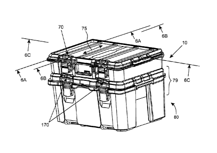
Articulating a first utility module with a second utility module is simple and
easy. In the following description, with reference being made also to Figs. 5
to 8B, a
utility module set 79 is illustrated, comprising two utility modules. The
first utility
module is the container 10 illustrated and disclosed in detail with reference
to Figs. 1 to
4H. The second utility module, in the illustrated example, is also a
container, similar to
container 10 however a larger one, generally designated 80, and wherein like
elements
are designated with like reference numbers, however shifted by 100.
For articulating the two utility modules 10 and 80, the first utility module
10 is
placed over the second utility module 80 such that the base 16 of the first
utility module
10 is allowed to slide within the arresting space 154 of the second utility
module 80,
namely with longitudinal ribs 18 displacing over longitudinal depressions 160
and
280585 00314/107471041 1
CA 3075155 2020-03-10
- 14 -
bottom surface 20 of the base 16 sliding over surface 152, introducing
engaging tabs 22
into the tab arresting receptacles 156. For this purpose, slanted end 32 of
the engaging
tabs 22 is advantages, as it does not constitute an obstacle upon placing the
first utility
module 10 tilted over the second utility module 80, in a sliding fashion
(Figs. 7 to 8B).
Once the first utility module 10 comes into place over the second utility
module
80, such that the engaging tabs 22 are arrested within the respective tab
arresting
receptacles 156, the locking latches 170 are displaced (manually sliding in
the example;
along the path of insertion) into the locked position, whereby the locking
tongues 172
are displaced into arresting engagement within tab locking receptacles 38,
however over
the flat top surface 44, thus arresting the first utility module 10 over the
second utility
module 80. At the articulated position the base plate 16 of the first utility
module 10 is
disposed substantially parallel with the arresting space 154 of the second
utility module
80.
It is noted, the engaging tabs 22 are configured, as far as shape and size,
for snug
receiving within the respective shape and dimensions of the top flat surface
28 of the
engaging tabs 22 and the height of the tab arresting receptacles 156, whereby
at an
interlocked position (Figs. 5 to 6C), when the engaging tabs 22 are received
within the
respective tab arresting receptacles 156, the top flat face 28 of the engaging
tabs 22 are
engaged under, at contact tolerance, with a facing surface 157 of the tab
arresting
receptacles 156.
Noticeable, the length of the base portion 16 of the first utility module 10,
measured in the direction of the path of insertion is substantially similar,
or slightly less,
than the length of the arresting space 154 of the second utility module 80,
measured in
the same direction, and wherein the length of the base portion 16 of the first
utility
module 10 including the protruding length of the engaging tabs 22 is greater
than the
length of the arresting space 154 of the second utility module 80.
In addition, the locking tongues 172 are configured for arresting the locking
receptacles 38 such that at the locked position, a bottom surface 173 of the
locking
tongues 172 bears over the bottom surface 42 of the locking receptacles 38, to
thereby
eliminate motion freedom between the utility modules at their interlocked,
locked
position.
280585 00314/107471041 1
CA 3075155 2020-03-10
- 15 -
The arrangement is such that once at the locked position, the first utility
module
and second utility module 80 are firmly articulated to one another, with
substantially
no tolerance, i.e. no free movement, as the base portion 16 is clamped at its
position
over the arresting space 154, and wherein detaching the utility modules from
one
5 another is easily performed simply by unlocking the locking latches 170 and
removing
the first utility module from the second utility module, where removing the
first utility
module 10 requires slight upwards tilting the front portion of the first
utility module, to
facilitate disengaging the engaging tabs 22 from the arresting receptacles
156.
In the illustrated examples hereinabove and hereinafter, the locking latches
are
10 displaceable between their respective locked and unlocked positions by
axial, sliding
displacement, along the path of insertion 75. However, it should be apparent
that the
locking latches can be configured for displacement about an axis intersecting
the path of
insertion 75, as will be exemplified hereinafter with reference to Figs. 9 to
10B. Also, it
should be apparent that rather than axial sliding, the locking lathes can be
configured for
5 displacement between the respective locked position and unlocked position
through
rotational or pivotal manipulation (not shown).
Further attention is now directed to Figs. 9 to 11, directed to an embodiment
of
the disclosure, however following the same principals. In the example of Figs.
9 to 11
there is illustrated a container assembly generally designated 90, comprising
a first
utility module 92 (namely the top container) and a second utility module 94
(the bottom
container), though is this example the two utility modules 92 and 94 are
identical and
thus the following description applies to both the containers.
Similar to the previous example, the utility modules 92 and 94 have a rigid
body
96 and a cover/lid 98 pivotally articulated thereto at a top back edge
thereof. The body
96 comprises a rigid base 200 (Fig. 11) configured with several (four in the
illustrated
example) longitudinal ribs 202 projecting from a bottom surface 204 of the
base 200,
said ribs 202 extending from a rear edge to a front edge of the base 200, said
ribs
terminating at engaging tabs 210. The engaging tabs 210 project from an
upright rear
wall portion 212 (Fig. 10C) of the base 200 (i.e. substantially vertical,
normal to the
bottom surface 204) and terminate such that their rear end, projecting
laterally
backwards from the base 200, does not exceeding behind a back wall of the
container.
280585 00314/107471041 1
CA 3075155 2020-03-10
- 16 -
The engaging tabs 210 are configured with a top flat face 214 (Fig. 10C), a
bottom face
216 and having a slanted end 218.
Unlike the previous example, in the present embodiment locking receptacles 220
are disposed at respective side wall portions of the base 200, such that they
do not
extend along the path of insertion. However, said locking receptacles 220
being similar
to those of the previous example, namely having a generally inverted U-like
shape, each
having a side facing opening, with a flat bottom surface 224 and a flat top
surface 226.
It is also seen that the base 200 has a tapering skirt portion 230 configured
for
assisting in positioning the container over another utility module as will be
seen with
reference to the assemblies illustrated and discussed hereinafter.
Similar to the previous example, the containers 92, 94 are each configured
with
complete connectivity features, facilitating it to be articulated over another
utility
module and/or facilitating another utility module to be articulated over it.
The pivotal lid 98 constitutes a rigid mounting platform, having an annular
rim/skirt 234 extending from a surface 238 and defining a utility module
arresting space
240, with four tab arresting receptacles 241 at a first location (namely a
back side of the
rim 234), said tab arresting receptacles 241 being thoroughgoing apertures
extending
through the rim 234.
At a second of location of the lid 98, namely at an opposite side portions
thereof,
there are configured two locking latches 244, facing each other, and each
having a pair
of locking tongues 246 extendable into the arresting space 240 and a
manipulating
portion 248 disposed external to said rim 234. The locking latches 244 are
slidingly
displaceable between a locked position where the locking tongues 246 project
into the
arresting space 240, and an unlocked position wherein the locking tongues 246
are
retracted and do not project into the arresting space 240, and their slanted
fore tip 250
extends substantially flush with an inside surface 254 of the rim 234, said
inside surface
254 tapering outwards. At the locked position, a bottom surface 256 of the
locking
tongues 246 is spaced from the surface of the arresting space 240.
Contrary to the previous example, in the present example the locking tongues
246 i.e. locking latches 244, are displaceable into engagement within the
locking
receptacles 220 along an axis normal to that the tab arresting receptacles,
(i.e. the
280585 00314/107471041 1
CA 3075155 2020-03-10
- 17 -
connectivity path). Other features of the connectivity system and the utility
module
system being substantially similar to those described hereinabove, mutatis
mutandis.
The side locking latches cab be in addition or instead of locking latches
disposed
at the front side of the utility module. However, when the locking latches are
displaceable along an axis normal to the path of insertion (i.e. the axis of
displacement
of the engaging tabs into tab arresting receptacles), than the foot print of
the rigid base
portion of the first utility module can be smaller than the foot print of the
arresting
space of the second utility module. Thus, at the event that the foot print of
the rigid base
portion of the first utility module being smaller than the foot print of the
arresting space
of the second utility module, then the first utility module can be slidingly
displaced into
locking arresting of the engaging tabs with the respective tab arresting
receptacles
without the need to tilt the first utility module.
Turning now to Figs. 12A to 13D, there is illustrated yet another example of a
utility module and a utility system 269, according to an embodiment of the
present
disclosure. In this example there is illustrated a utility module 270 (Figs.
12A and 12B)
configured as an open top container, i.e. devoid of a lid. Nevertheless,
container 270 is
configured with a complete set of connectivity features according to the
disclosure.
Accordingly, the container 270 is a bucket-like container configured with a
rigid
base portion 274 (Figs. 13A and 13B) with upwardly extending front wall 276,
rear wall
278 and two side walls 280, defining together a top rim 284 constituting a
rigid
mounting platform, wherein an arresting space 285 is defined by the boundaries
of the
rim 284. A rear portion of the rim 284 is configured with four tab arresting
receptacles
286, in the form of thoroughgoing openings, and a front portion of the rim
slidingly
accommodated two locking latches 290, extending within the rim 284 into the
arresting
space 285 (at their locked position), and having a manipulating portion 296
disposed
external to said rim 284. An annular inside shoulder 298 is configured below
the rim,
wherein said rim can be continuous or intermitted. In fact, the rigid mounting
platform
with the arresting space 285, the tab arresting receptacles 286 and locking
latches 290
are similar by construction to the previous examples, with the exception of
emittance of
a rigid surface.
The rigid base 274 of the container 270 is configured with respective engaging
tabs and locking receptacles, rendering the container 270 suitable for
constituting a 'first
280585 00314/107471041 1
CA 3075155 2020-03-10
- 18 -
utility module', i.e. suitable for mounting over another utility module of
same nature,
configured in turn with complimentary connectivity components, namely locking
latches and tab arresting receptacles.
In Figs. 12A and 13A to 13D the container 270 is however considered as a
second utility module, having articulated thereto, over a portion of its open
top, a first
utility module, namely a small container 302, seen isolated in Figs. 17A and
17B. Apart
for its size, container 302 is similar to any of the containers (utility
modules) disclosed
hereinabove and reference is made back for further details concerning the
connectivity
features thereof, namely its rigid base portion 306 configured with engaging
tabs 308 at
a back side and a single tab arresting receptacle 310 at a front side.
Likewise, it is noted
a lid 314 is pivotally articulated at a top of the container 302, the lid
configured in turn
with connectivity features, namely tab arresting receptacles 320 and a single
sliding
locking latch 324.
However, at an articulated position, the first utility module, i.e. container
302
occupies only a portion of the arresting space 285 whereby an additional small
sized
container (not shown) can be placed for covering the entire open top container
270.
Alternatively, a full sized utility module can be articulated over the open-
top container.
It is noted that articulating the container 302 over container 270 is
facilitated
exactly as described in connection with the first example, and wherein an
annular skirt
330 of the base portion 306 is supported over the annular shoulder 298.
Arresting of the
container 302 over container 270 is likewise facilitated by locking tabs
engaging
respective tab arresting receptacles and the locking latches are displaced
into locking
latches arresting with the locking receptacles.
Still an example of a utility module, fitted with a connectivity arrangement
according to as aspect of the disclosure is illustrated in Fig. 14A directed
to a rigid
mounting platform 340 being a rigid platform configured for attaching to a
carrying
surface such as a wall, a truck bed, or any other carrying structure (not
shown), e.g. by
fasteners extendable through openings 342.
A top face of the mounting platform 340 is configured with connectivity
components of a second type utility module, i.e. a utility module arresting
space 344
delimited by an annular rim 346, and configured with four tab arresting
receptacles 348
at a first location (i.e. a rear face thereof, which at a vertical display of
the of the
280585 00314/107471041 1
CA 3075155 2020-03-10
- 19 -
mounting platform 340 is a bottom edge), and a pair of locking latches 350
disposed at
an opposite, second location. The locking latches 350 are displaceable between
a locked
position, projecting into said utility module arresting space 344 and are
engageable
with a locking receptacle 310 in the container 302 (as in Figs. 17A and 17B,
being
similar to the container articulated to the mounting platform 340), and an
unlocked
position, wherein said locking latches are retracted from said utility module
arresting
space 344.
Similar to the previous examples, the top face of the mounting platform 340 is
configured with several longitudinal depressions 360 extending between
elevated
to surfaces 362, over which a first utility module can easily slide into
engagement, as
described hereinbefore with reverence to earlier examples. Articulating and
locking a so
called 'first utility module', e.g. container 302, is facilitated in the same
manner as
described hereinbefore, namely by first engaging the engaging tabs 308 with
the
respective tab arresting receptacles 348, and upon positioning the rigid base
306 of
container 302 over the arresting space 344 the locking latch 350 can be
displaced into
its locked position, projecting into the space 344 and into arresting
engagement with the
tab arresting receptacle 310 of the container 302.
When the mounting platform 340 is placed over a substantially horizontal
surface there is no practical meaning to its positioning. However, when the
mounting
platform 340 is attached to a substantially vertical wall structure, it is
practically
advantageous that the mounting platform 340 be placed with the tab arresting
receptacles 348 at a bottom location and the locking latches 350 above.
Turning now to Fig. 18, there is illustrated a wheeled dolly generally
designated
370. The dolly 370 is principally of same structure as mounting platform 340,
however
in addition to connectivity features (i.e. tab arresting receptacles 374 and
locking
latched 376) it is further configured for locomotion over caster wheels 378,
and wherein
articulating thereto and detaching therefrom, a so-called 'first utility
module' takes place
in the same manner as already explained hereinabove.
280585 00314/107471041 1
CA 3075155 2020-03-10