Note: Descriptions are shown in the official language in which they were submitted.
CA 03075255 2020-03-06
WO 2019/050410
PCT/N02018/050015
- 1 -
Marine Suction Anchor
This invention relates to a marine suction anchor for use as the foundation
and support of a subsea well, such as a hydrocarbon well. In particular, it
relates to
such a structure that provides integral support to a wellhead housing whereby
bending moments applied to that housing, such as riser-induced loads, may be
absorbed.
A suction anchor is a device that forms a closed volume with the sea bed (or
whichever surface it is to be sucked into) and in which the pressure can be
adjusted
so that it can be moved relative to the seabed. This is achieved by reducing
the
pressure inside the suction anchor to be less than the external sea pressure
at the
depth at which the suction anchor is located so that the suction anchor is
sucked/pushed into the sea bed by the pressure differential created.
Conversely, if
it is desired to uninstall the suction anchor, this may be achieved by
increasing the
pressure inside the suction anchor to be greater than the external sea
pressure at
the depth at which the suction anchor is located so that the suction anchor is
forced
out of the sea bed by the pressure differential created.
Suction anchors are increasingly being adopted as foundations for subsea
wells, typically hydrocarbon wells. Once the suction anchor has been installed
in
the sea bed, a conductor ¨ i.e. a pipe forming an outer casing for the well ¨
is
installed through the centre of the suction anchor into the sea bed, for
example by
piling or cementing it into an oversize hole. Once the conductor has been
installed,
the wellhead may be landed into the conductor such that it extends above the
suction anchor, with a wellhead casing extending downwardly within the
conductor.
Examples of known suction anchors of this type are disclosed in WO
01/65050 and WO 2010/068119. In each case, a central opening is provided in
the
upper surface of the anchor for receiving the conductor, wellhead, etc. Both
of
these documents also illustrate the provision of a central pipe depending from
the
central opening for receiving the conductor etc. WO 01/65050 in particular
describes how this provides lateral support to the conductor, both during
piling/installation and also to absorb forces and loads applied to it when it
is later
used as an anchoring point for the wellhead. It also discloses the provision
of radial
internal supporting walls extending nearly the full height of the anchor that
serve to
support the central pipe against both the outer wall and upper surface of the
anchor.
CA 03075255 2020-03-06
WO 2019/050410
PCT/N02018/050015
- 2 -
Another known suction anchor is disclosed in WO 2013/167872, where it is
illustrated with a high pressure wellhead installed. This is provided with an
integral
conductor, in place of the central pipe described above, for receiving a
wellhead
casing. Radially extending internal walls are provided within a domed upper
surface
of the anchor by way of reinforcements.
A typical subsea wellhead assembly comprises the subsea wellhead (i.e.
high pressure wellhead housing) to which subsea riser system equipment, such
as
a blowout preventer ¨ BOP - (which may comprise a lower stack and a lower
marine riser package (LMRP)) and/or a Christmas tree (which may also be
referred
to as a subsea tree) may be connected. The subsea riser system equipment is
connected (in a downwards direction) to the wellhead and is typically
connected (in
an upwards direction) to a riser that extends between this riser system
equipment
and a surface facility, such as a floating vessel. The riser typically
provides a
conduit for the drill string and drilling fluids between the subsea well and
the surface
facility.
It is important that the wellhead assembly's integrity is maintained so that
structural failure and uncontrolled release of well fluids does not occur. As
a result,
it is desirable that forces that act on the assembly have as low risk as
possible of
damaging the assembly.
?CI One source of such forces is the bending moment that may be applied to
the wellhead by the swaying motion of the relatively massive BOP and other
components located above the wellhead. This may lead to deformation of the
wellhead and ultimately fatigue failure causing it to rupture.
As discussed above, it is known for suction anchors to be provided with
internal structures that may serve to provide lateral support to the conductor
and
hence to the wellhead housing and/or casing received within it. WO
2016/085348,
on the other hand, proposes the provision of a separate supporting frame that
may
be mounted on top of a wellhead foundation in order to transfer bending moment
exerted on the wellhead to the foundation and into the ground. The frame
comprises horizontal beams that extend radially from the wellhead and which
are
provided with downwardly extending feet at their circumferential ends. These
in turn
have abutments that rest on top of the foundation.
According to a first aspect of the invention there is provided a suction
anchor comprising: a suction chamber bounded by: (i) a circumferential outer
wall,
(ii) an upper wall having a central opening, and (iii) the wall of an internal
housing;
CA 03075255 2020-03-06
WO 2019/050410
PCT/N02018/050015
- 3 -
the internal housing defining a passage in communication with the central
opening
for receiving wellhead components that may be secured to the suction anchor;
the
suction chamber having a minor upper portion and a major lower portion; the
minor
upper portion comprising internal reinforcing members extending along the
inside of
the upper wall from the outer walls to the internal housing; the major portion
being
adapted to be embedded in a seabed and the minor portion being adapted to
project from the seabed when the anchor is installed; wherein the reinforcing
members serve both to reinforce the upper wall of the chamber against collapse
and to rigidly support the internal housing such that it may resist forces
applied to it
arising from bending moments applied to a wellhead component received and
secured therein.
Thus, the suction anchor of the present invention is configured such that the
reinforcements used to provide the necessary strength to the upper wall of the
suction chamber also serve to transmit lateral forces applied to the wellhead
to the
suction anchor and thus to the seabed. As such, the wellhead may be protected
against bending moments applied to it by components such as a BOP located
above it without the need for additional components, such as a supporting
frame,
and in particular the need to install such components onto the suction anchor
at the
seabed.
The present invention renders the separate supporting frame superfluous
because bending moment is effectively transferred to the reinforcing members,
which constitute the structural support of the upper wall of the suction
anchor and
also assumes lateral and horizontal forces exerted on the wellhead. Thereby,
both
the structural design and the installation procedures are simplified. The
present
invention therefore provides a suction anchor that addresses at least some of
the
drawbacks found in the prior art.
It should be noted that the term "central" and similar terms used herein are
not intended to refer to the precise geometrical centre of the suction anchor.
Rather, the term is used to refer to the region at or towards the centre of
the suction
anchor that is surrounded by the suction chamber. Likewise, "circumferential
wall" is
not intended to refer only to circular structures, but to any wall defining
the
perimeter of a suction chamber; that perimeter may be circular or polygonal
(regular
or otherwise).
Since the major portion is that part which is adapted for being embedded in
the sea bed when installed and the minor portion is adapted to project from
the sea
CA 03075255 2020-03-06
WO 2019/050410
PCT/N02018/050015
- 4 -
bed, the reinforcements being located only at the upper part of the suction
chamber
(i.e. in the minor portion thereof) do not obstruct the movement of the
suction
anchor into the seabed_
To facilitate its embedding into the seabed, the major portion may be
substantially void of further internal components, and in particular, the
reinforcements provided in the minor portion should not extend into the major
portion. Indeed, preferably, the reinforcements themselves lie on the sea bed
when
the suction anchor is fully installed. However, it may be necessary to provide
certain
additional bracing members within the major portion to support other
components
provided beneath the internal housing.
The internal housing may be adapted to directly receive wellhead
components (e.g. a wellhead housing). However, preferably the internal housing
is
a conductor housing receptacle adapted to receive a conductor housing. This
has
the advantage that standard wellhead components may then be mounted into the
conductor housing in the conventional manner. Accordingly, the conductor
housing
receptacle preferably further comprises a conductor housing located therein
and
rigidly secured thereto, the conductor housing being adapted to receive a
wellhead
component.
In these arrangements, the conductor housing may be secured to the
conductor housing receptacle by any convenient manner, e.g. by welding.
However,
it is preferred that the conductor housing is clamped into the conductor
housing
receptacle. For example, it may be supported at a lower part thereof by a
support
ring against which it may be clamped by a clamping ring.
The reinforcing members make take any suitable form and configuration that
both provides sufficient resistance against collapse of the upper wall (i.e.
implosion)
and sufficient rigidity to the wall of the internal housing. One convenient
arrangement is for the reinforcing members to extend radially from the wall of
the
internal housing to the outer wall ¨ e.g. like spokes in a wheel. The
reinforcement
members themselves may, for example, be l-beams.
The suction anchor preferably further comprises a central (inner) pipe
depending from the internal housing. This serves to bound the inner part of
the
major portion of the suction chamber. Thus, it may form a downward extension
to
the internal housing and/or a conductor housing located therein. As such, it
may be
adapted to receive a well casing depending from a wellhead secured in the
internal
housing. By means of this arrangement, it is not necessary for there to be a
CA 03075255 2020-03-06
WO 2019/050410
PCT/N02018/050015
- -
conductor extending below the conductor housing in the conventional manner. If
necessary, the central pipe may be secured against lateral movement by means
of
one or more bracing members within the major portion, as mentioned above. Such
components are to be distinguished from the reinforcements found in the minor
portion. Preferably, such bracing members would be provided in the lower part
of
the major portion and hence distant from the reinforcements. They may extend
from
such a central pipe to the outer wall.
The suction anchor preferably further comprises a suction port to enable air
and/or water to be pumped from the suction chamber. It may also have a
plurality of
attachment points, such as pad eyes, are provided at the upper wall to
facilitate
lowering/raising the suction anchor to/from the seabed and otherwise handling
and
transporting it.
The shape and form of the suction anchor is not critical to the invention.
However, for reasons of strength and simplicity, it is preferably generally in
the form
of a cylinder with one closed end. Thus, preferably the outer wall is
cylindrical. As
such, the suction chamber is preferably annular. Likewise, the internal
housing is
preferably generally cylindrical and may be co-axial with the outer wall.
Although
the upper wall may, for example, be domed, a flat upper surface is more
convenient
and so the upper wall is preferably substantially planar.
In use, the suction anchor described above may typically be provided in
combination with a wellhead housing and a wellhead casing, wherein the
wellhead
housing is rigidly secured within a conductor housing and the conductor
housing is
rigidly secured within the internal housing, whereby lateral forces applied to
the
upper part of the wellhead casing are transmitted to the suction anchor.
Furthermore, in use the combination may further comprise a wellhead valve,
such as a BOP, mounted above the wellhead housing.
The combination will preferably be installed such that the major portion
beneath the seabed and the minor portion projecting therefrom.
It follows that the invention also extends to a method of installing some or
all
of the components discussed above. Accordingly, viewed from another aspect,
the
invention provides a method of installing a subsea structure comprising
providing a
subsea anchor as described in the first-described aspect above, locating the
subsea anchor on the sea bed and pumping air and/or water from the suction
chamber such that the subsea anchor descends into the sea bed.
CA 03075255 2020-03-06
WO 2019/050410
PCT/N02018/050015
- 6 -
The subsea anchor may also have the optional preferred features discussed
above. Thus, for example, it is preferably installed in a seabed such that the
major
portion is beneath the seabed and the minor portion projecting therefrom.
Likewise, the invention may further comprise the step of landing wellhead
component(s) in the internal housing. The wellhead components may comprise a
wellhead housing (preferably a high pressure wellhead housing) with a wellhead
casing depending therefrom.
The method may further comprise subsequent steps where further
components are installed at the sea bed. Thus, for example, it may further
comprise
installing a wellhead valve, such as a BOP, mounted above the wellhead
housing.
An embodiment of the invention will be described, by way of example only,
and with reference to the following drawings in which:
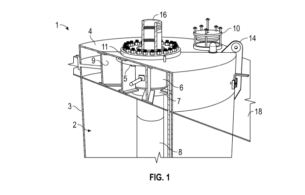
Figure 1 shows a perspective view of a suction anchor according to an
embodiment of the invention in partial cross section;
Figure 2 shows a cross section view of the suction anchor with a cross
section through the centre of the suction anchor; and
Figure 3 shows an enlargement of a portion of the cross section of Figure 2.
With reference to Figures 1 and 2, a suction anchor foundation 1 comprises
an annular closed volume forming a suction chamber 2. This closed volume is
bounded by a cylindrical outer suction skirt 3 and an annular connection
portion 4 in
the form of a planar "lid". Together these define the major part of the outer
surface
of the suction anchor 1.
Within the suction anchor 1 the chamber is further bounded at its upper end by
receptacle support ring 5, a cylindrical conductor housing receptacle 6 and
inner
pipe support ring 7. Beneath these, central/inner pipe of the suction anchor 8
extends downwardly towards the base of the suction anchor. The inner pipe 8 of
the
suction anchor 1 has the diameter of a conventional conductor (e.g. 30
inches).
These components are all arranged co-axially with the outer suction skirt 3.
Extending radially from the conductor housing receptacle 6 to outer suction
skirt 3 are a plurality of I-beam reinforcements 9.
As shown most clearly in Figure 2, the l-beams 9 extend radially within the
internal volume from the outer surface of the conductor housing receptacle 6
to the
outer suction skirt 3. The l-beams 9 are each welded at their radially inner
end to a
conductor housing receptacle 6, inner pipe support ring 7 and receptacle
support
ring 5, and at their radially outer end to the suction skirt 3 of the suction
anchor.
CA 03075255 2020-03-06
WO 2019/050410
PCT/N02018/050015
- 7 -
Additionally, the I-beams 9 are welded along the length of their top surface
to the
underside of the annular connection portion 4. As such, these components form
a
strong and rigid structure.
A number of other components are provided at the upper end of the suction
anchor 1.
One of these is pump port 10 for connection via a pipe to a vacuum pump
for removing air and water from the suction chamber 2 as will be described
below.
In addition, a number of pad eyes 14 are located around the circumference
of the top annular connection portion. These pad eyes may be used to help lift
and
support the suction anchor 1 during installation and removal.
At the centre of the annular connection portion 4 is provided a clamp ring
11. This surrounds the central opening in the annular connection portion and
co-
operates with receptacle support ring, to which it is bolted, to secure a
conductor
housing 12 within the conductor housing receptacle 6. The clamp ring 11 acts
against a protrusion towards the upper end of the conductor housing 12. The
lower
end of the conductor housing 12 rests on mount ring 15, which in turn is
supported
by an annular shoulder of support ring 7. This arrangement may most clearly be
seen from Figure 3.
Thus, the conductor housing 12 is clamped into the conductor housing
receptacle 6 at the upper end thereof by clamp ring 11, compressing the
conductor
housing 12 against the mount ring 15 on the inner pipe support ring 7. As a
result,
conductor housing 12 is securely and rigidly attached to the conductor housing
receptacle 6 and in turn to l-beams 9 etc.
The mount ring 15 can act as an adapter to allow the suction anchor 1 to be
used with different sizes and geometry of conductor housings 12 that may be
provided by different suppliers.
Note also from Figure 3 that the conductor housing receptacle 6 is fixed at
its top end to the annular connection portion 4 of the suction anchor via
receptacle
support ring 5. It may also be seen that, at the bottom end of the conductor
housing receptacle 6, inner pipe 8 is hung from inner pipe support ring 7.
Extending though the conductor housing 12 is high pressure wellhead
housing 16 that supports a wellhead casing 17 extending through the middle of
the
suction anchor as shown most clearly in Figure 2. The high pressure wellhead
housing 12 is the component onto which wellhead valves such as a BOP are
mounted in use.
CA 03075255 2020-03-06
WO 2019/050410
PCT/N02018/050015
- 8 -
When the suction anchor 1 is to be installed, it is lowered to the sea bed 18
by means of cables attached to pad eyes 14. At this stage, it comprises the
conductor housing 12, but not the wellhead 16 or wellhead casing 17.
Once placed on the sea bed 18, the suction anchor 1 will generally self-
penetrate a certain depth into the sea bed (the exact depth depending on
factors
such as the weight of the suction anchor and the geology of the sea bed) such
that
the inner pipe 8 and outer suction skirt 3 penetrate into the seabed 18 to
form the
closed sealed volume 2 within which the pressure can be adjusted. The pressure
is
reduced by connecting the pump port 10 (shown in expanded form in Figures 1
and
2) in the top annular connection plate 4 to a pump (not shown). The pump
removes
air and/or water from inside the internal annular volume 2 to reduce the
pressure.
The suction anchor may thus be sucked into the seabed 18 until radially
extending
l-beams 9 within the internal annular volume contact the seabed 18 as shown in
Figures 1 and 2. As the pressure is reduced in the internal annular volume of
the
suction anchor, the l-beams serve to reinforce the annular connection portion
4
against implosion or collapse.
Subsequently, the high pressure wellhead housing 16 and wellhead casing
17 are installed. The former is landed in the conductor housing to provide the
configuration shown in the figures. It supports wellhead casing 17, which
forms an
extension thereof. Thus, these components extend downwardly through the inner
pipe 8 of the suction anchor 1. It will be noted that, contrary to a typical
well, the
conductor housing 12 does not support a conductor casing. This is because the
conductor casing is not required due to the presence of the inner pipe 8,
which
performs a corresponding function.
It will be appreciated that the conductor casing 12 and associated
components serve to secure the wellhead casing 17 securely and rigidly
relative to
the conductor housing receptacle, l-beams, etc. In particular, the mount ring
15 (at
the top) and the clamp ring 11 (at the bottom) each provide a load
transmitting
connection point between the conductor housing 12 (and hence a wellhead
secured
within it) and the suction anchor. As such, lateral forces or
bending/rotational forces
about a horizontal axis applied to the conductor housing and wellhead may be
resisted because there is a load path from the wellhead to the seabed.
Prior to use, wellhead valves such as a blowout preventer (BOP ¨ not
shown) are connected to and mounted on top of the high pressure wellhead 16 in
the known manner. As is well known in the art, these components are relatively
CA 03075255 2020-03-06
WO 2019/050410 PCT/N02018/050015
-9..
massive and tend to apply significant lateral forces to the upper part of the
wellhead
¨ i.e. they apply a bending moment to it.
Because the I-beams 9 are secured to the conductor housing receptacle 6
as well as to the annular connection portion 4 (the lid of the suction
anchor), in
addition to reinforcing the suction chamber, they serve the important function
of
providing a load path through which loads exerted on the wellhead can be
transferred into the suction anchor before ultimately being transferred into
the
seabed. Accordingly, the suction anchor is able to protect the wellhead 16
from
damage that might be caused by horizontal components of force caused by the
BOP or other components connected above it.