Note: Descriptions are shown in the official language in which they were submitted.
Attorney Docket No.: 72329-897645.02
PATENT
1
TOP CAP
DESCRIPTION
CROSS-REFERENCE TO RELATED APPLICATIONS
[0001] The present invention claims priority to and the benefit of U.S.
Patent Application
No. 16/814,195 filed March 10, 2020, and U.S. Provisional Patent Application
No. 62/817,692
filed March 13, 2019, the contents of which are incorporated herein by
reference.
FEDERALLY SPONSORED RESEARCH OR DEVELOPMENT
[0002] N/A
FIELD OF THE INVENTION
[0003] The present invention is generally directed to an improved top cap
without a full
perimeter lip for use in moving stacked totes on a transport system such as a
pallet; and more
particularly to a top cap having a plurality of puck shaped structures
projecting downward to
contain stacks of totes without a conventional perimeter lip.
DESCRIPTION OF THE PRIOR ART
[0004] Molded plastic top caps are often used in combination with pallets
and other transport
apparatus to provide unitized transport systems to move various loads. The
loads can include
stacks of containers or totes such as those shown in Figure 1. Straps can be
tightened around the
pallet and top cap to keep the load secure. In most, if not all such
instances, the top cap includes
a downwardly extending, continuous lip around the entire perimeter of the top
cap to contain the
stacks of totes on the pallet. This, in part, can limit the number of
transport systems that can be
loaded into a trailer of a truck for shipping.
[0005] The present invention provides a top cap that can be used in a
transport system having
a reduced footprint such that it is possible to fit additional transport
systems in a standard trailer
of a truck.
77191
CA 3075535 2020-03-12
Attorney Docket No.: 72329-897645.02
PATENT
2
SUMMARY OF THE INVENTION
[0006] The present invention is directed to an improved top cap having a
plurality of puck
shaped projections for containing stacks of totes on a pallet. The projections
allows for removal
of a continuous lip around the entire perimeter of the top cap ¨ thus enabling
creation of a
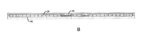
transport system having a smaller footprint (than the conventional top cap
allowed for).
[0007] In accordance with one aspect of the present invention, a top cap is
provided
comprising a generally rectangular upper surface having a first side edge, a
second side edge
opposing the first side edge, a first end edge and a second end edge opposing
the first end edge.
The upper surface of the top cap includes a plurality of tote contacting
projections extending
downwardly from the upper surface. The projections are in a pattern configured
to enable each
projection to contact a corner portion of a tote when the top cap is placed on
a plurality of totes.
In some instances, the top cap can include additional projections positioned
to contact the totes at
other (non-corner) locations.
[0008] The top cap can also include a lower surface opposing the upper
surface. A plurality
of ribs can extend downward from the lower surface. The plurality of ribs can
include a first
portion extending in a parallel formation from the first side edge to the
second side edge. A
second portion of the plurality of ribs can extend in a parallel formation
from the first end edge
to the second end edge.
[0009] The plurality of tote contacting projections are configured to
extend downward
further than a lower edge of the plurality of ribs. In this regard, the tote
contacting projections
include a contact portion below the lower edge of the plurality of ribs that
is generally cylindrical
(in practice, each of the plurality of tote contacting projections has a
generally hollow conical
shape). The corners of the totes are typically rounded or arcuate, and the
contact portion is
configured to engage an inner corner of the tote. Preferably, the contacting
portion has the same
radius as the corner.
77191
CA 3075535 2020-03-12
Attorney Docket No.: 72329-897645.02
PATENT
3
[0010] The top cap is configured so that it does not include a continuous
lip around its
periphery. In one configuration, each of the first end edge and the second end
edge includes a
downwardly extending lip while the first side edge and the second side edge
are lipless.
[0011] The top cap can also include a plurality of downwardly extending
depressions and/or
upwardly extending projections in the upper surface. The
depressions/projections can be
configured to mate with a footprint of one or more other transportation
systems that may be
stacked on the top cap.
[0012] In accordance with another aspect of the invention, a top cap for
use in combination
with a transport system is provided. The top cap comprises a rectangular layer
of material
having a first side edge, a second side edge, a first end edge, a second end
edge, an upper surface
and a lower surface. The layer of material can include a plurality of ribs
extending downward
from the lower surface. Additionally, the top cap includes a plurality of
spaced apart projections
of the layer of material for contacting totes when the top cap is placed on
stacks of totes. If the
top cap includes lower ribs, the projections need to extend downward below a
lower edge of the
ribs.
[0013] Each of the projections has a generally cylindrical or slightly
conical shape.
Additionally, each of the projections includes a puck shaped portion that
extends beyond the
lower edges of the ribs. The puck shaped portion is configured to engage a
portion of the top of
a tote.
[0014] The plurality of ribs can include a first series of parallel ribs
extending between the
first side edge and the second side edge and a second series of parallel ribs
extending from the
first end edge to the second end edge. The first series of ribs are
perpendicular to the second
series of ribs. The ribs can be spaced closely or further apart in different
portions of the lower
surface of the top cap.
[0015] Each of the projections is positioned to contact a top of a tote
when the top cap is
placed on a plurality of stacks of totes. In particular, each projection is
configured to contact an
inner radius of a corner of the tote. The projections can be positioned in a
pattern to contact
twelve stacks of totes fitting on a pallet. The projections can be also be
positioned for other tote
sizes, e.g., four, six, etc., that fit on the pallet.
77191
CA 3075535 2020-03-12
Attorney Docket No.: 72329-897645.02
PATENT
4
[0016] The top caps can be formed from a molded plastic. Other similar or
suitable materials
can also be used. The top cap can be a single piece or can be composed of
multiple pieces
connected to each other.
[0017] Other features and advantages of the invention will be apparent from
the following
specification taken in conjunction with the following Figures.
BRIEF DESCRIPTION OF THE DRAWINGS
[0018] To understand the present invention, it will now be described by way
of example,
with reference to the accompanying drawings in which:
[0019] FIG. 1 is a perspective view of a known top cap on top of a
plurality of totes stacked
on a pallet;
[0020] FIG. 2A is a shaded perspective views of a top cap in accordance
with the present
invention;
[0021] FIG. 2B is a wireframe perspective view of the top cap of FIG. 2A;
[0022] FIG. 3A is a shaded top plan view of the top cap of FIG. 2A;
[0023] FIG. 3B is a wireframe top plan view of the top cap of FIG. 2A with
the top edges of
ribs extending from a bottom surface of the top cap visible;
[0024] FIG. 4A is a shaded bottom perspective view of the top cap of FIG.
2A;
[0025] FIG. 4B is a wireframe bottom perspective view of the top cap of
FIG. 2A;
[0026] FIG. 5A is a shaded bottom plan view of the top cap of FIG. 2A;
[0027] FIG. 5B is a wireframe bottom plan view of the top cap of FIG. 2A;
[0028] FIG. 6 is an enlarged wireframe bottom perspective view of a portion
of the top cap
of FIG. 2A;
[0029] FIG. 7A is a shaded side plan view of the top cap of FIG 2A;
[0030] FIG. 7B is a wireframe side plan view of the top cap of FIG 2A;
[0031] FIG. 8A is a shaded end plan view of the top cap of FIG 2A;
[0032] FIG. 8B is a wireframe end plan view of the top cap of FIG 2A;
[0033] FIG. 9 is a perspective view of a puck shaped portion of a
contacting projection of the
top cap of FIG. 2A;
77191
CA 3075535 2020-03-12
,
,
Attorney Docket No.: 72329-897645.02
PATENT
[0034] FIG. 10 is a schematic view showing placement of the
projections of the top cap on
top of twelve stacks of totes;
[0035] FIG. 11 is a schematic view showing placement of the
projections of the top cap on
top of four stacks of totes;
[0036] FIG. 12 is a schematic view showing placement of the
projections of the top cap on
top of six stacks of totes;
[0037] FIG. 13 is a combined top and bottom perspective view of the
top cap of FIG. 2A;
[0038] FIG. 14 is a top plan view of another top cap in accordance
with a another aspect of
the present invention;
[0039] FIG. 15 is a top plan view of stacks of totes which are
configured for use with the top
cap of FIG. 14;
[0040] FIG. 16 is a perspective view of a plurality of totes of
FIG. 15.
DETAILED DESCRIPTION
[0041] While this invention is susceptible of embodiments in many
different forms, there is
shown in the drawings and will herein be described in detail preferred
embodiments of the
invention with the understanding that the present disclosure is to be
considered as an
exemplification of the principles of the invention and is not intended to
limit the broad aspect of
the invention to the embodiments illustrated.
[0042] In industrial markets, the common pallet size is 45x48".
This size pallet limits load
transport to 26-floor positions in a standard 53' trailer (i.e., 26 pallets
with top caps transport
systems per trailer). By adjusting the width down to 44.5", it is possible to
get an additional 2-
floor positions per trailer, making 28-floor positions total.
[0043] Adjusting the width of the pallet down to 44.5" requires
shrinking all the components
in the width dimension. The problem with this approach is all the existing 26-
position system
components presently in the field. That is, backwards compatibility with 26-
position
components must be maintained. The pallet and totes can accomplish such
backwards
compatibility using existing design elements. However, the top cap is unique
in that it requires a
new approach to achieve acceptable containment of the totes.
77191
CA 3075535 2020-03-12
Attorney Docket No.: 72329-897645.02
PATENT
6
[0044] The totes (e.g., such as StakPaks) the top cap contains have a
maximum footprint of
45x48" for 26-floor positions and 44.5x48" for 28-floor positions. With a
maximum width of
44.5", this leaves no room for a downwardly extending lip on the short sides
of the top cap.
Instead, the present invention provides a top cap that engages internal
surfaces of the totes using
a pattern of "puck" shaped features that protrude beneath the top cap. These
puck shaped
features engage the inner corner radii of the totes in such a way as to
prevent them tipping
outward toward the long (48") sides, while not impeding on the totes fill
space. The puck pattern
is designed to engage different patterns of totes, as shown in Figures 10-12.
[0045] As shown in Figure 1, a conventional (prior) transport system 10
includes a pallet 12,
a top cap 14, and a plurality of stacks of totes 16 between the pallet 10 and
the top cap 14. Straps
18 are provided to secure the top cap 16 and stacks of totes 16 to the pallet
12. The top cap 14
includes a lip 20 around each of the sides and ends of the top cap 14.
[0046] A top cap 22 in accordance with the present invention is shown in
Figures 2A and B.
As shown, Figure 2A is a shaded form of an electronic drawing of the top cap
and Figure 2B is a
wireframe form of the same drawing. [In these ¨ and certain other Figures ¨
additional shading
and lines (such as framing lines 11 in Figure 2B) ¨ may be present. Applicant
intends on
preparing formal drawings removing these extra components from the Figures and
modifying the
specification accordingly (i.e., such as deleting this bracketed
explanation).].
[0047] The top cap 22 is a layer of material having a generally rectangular
shape with a first
side edge 24, an opposing second side edge 26, a first end edge 28, and an
opposing second end
edge 30. An upper surface 32 (and a corresponding lower surface 38 not shown
in Figures 2A
and B) extends between the side and end edges 24, 26, 28, 30.
[0048] As evident in the perspective views of Figures 2A and B, and in the
top plan views of
Figures 3A and B, the upper surface 32 of the top cap 22 includes a plurality
of spaced apart
circular openings 34. These openings 34 are formed by downward projections of
the top cap 22.
The upper surface 32 of the top cap 22 also includes a plurality of
depressions 36 having a
variety of shapes (the depressions are positioned lower than a plane defined
by the remaining
portion of the upper surface ¨ such features can also include upward
projections from that plane).
The depressions 36 are shaped and positioned to mate with the footprint of one
or more other
77191
CA 3075535 2020-03-12
Attorney Docket No.: 72329-897645.02
PATENT
7
transport systems that might be stacked on top of the top cap (e.g., the
bottom structure of other
pallets, or bulk bins, for example).
[0049] Referring to Figures 4-6, the underside of the top cap 22 includes a
lower surface 38,
and a plurality of ribs 40 that extend downward from the lower surface 38. The
ribs 40 are
generally perpendicular to each other with a plurality of parallel ribs
extending between the first
side edge 24 and the second side edge 26, a plurality of parallel ribs
extending between the first
end edge 28 and the second end edge 30. The lower edges of the ribs end in or
define a plane.
[0050] In some portions of the bottom of the top cap 22, the ribs 40 are
closer to each other
than in other portions of the bottom. Although shown in a particular
configuration, the ribs can
be other configurations as desired.
[0051] In addition to the ribs 40, the top cap 22 includes a plurality of
projections 42
extending downward from the lower surface 38. The projections 42 align with
the circular
openings 34 on the upper surface 32 of the top cap 22. The projections 42 are
shown having a
generally conical (almost cylindrical) outer surface 44 that cuts off at the
bottom (while the
projections are shown as conical, other shapes can be utilized).
[0052] As more clearly illustrated in the enlarged view of Figure 6 and the
side plan views of
Figures 7A and B, the projections 42 extend below the lower edges of the ribs
40. This leaves a
contacting portion 44 of the downward projection 42 exposed to contact the
tops of totes when
the top cap 22 is placed on top of the stacks of totes 16. The contacting
portion 44 has a puck-
like shape. This puck-like shape of the contacting portion 44 is more evident
in Figure 9 which
shows only the contacting portion 44. The contacting portion 44 can have a
complete or partial
opening on the bottom ¨ i.e., contacting side, of the contacting portion. 44.
[0053] The projections 42 shown are hollow. However, if additional support
is needed in the
projection, it may be possible to add internal structure (either an additional
piece, or molded in
ribs, etc.) to the projections 42.
[0054] As also evident in Figures 7A and B, as well as in Figures 8A and B,
the top cap 22
does not include a downwardly extending lip along the first and second side
edges 24, 26. While
the top cap 22 is lipless along the first and second side edges, in the
embodiment shown, a
downwardly extending lip 46 does extend from the first end edge 28 and the
second end edge 30.
77191
CA 3075535 2020-03-12
Attorney Docket No.: 72329-897645.02
PATENT
8
That is, only the end edges have a lip. The lips 46 are not continuous about
the periphery of the
top cap 22.
[0055] The projections 42 in the top cap 22 are spaced from each other, and
are configured in
a pattern for proper placement when the top cap 22 is positioned on various
stacks of totes 16.
The projections 42 are designed to place pressure at key locations on the
stacks of totes 16 to
contain the totes 16 in a unitized system with a pallet and straps.
[0056] Referring to Figures 10, 11 and 12, various configurations are
provided for different
sized totes. Figure 10 illustrate placement of the projections 42 on twelve
stacks of totes 16
positioned in a 3X4 matrix. Figure 11 shows placement of the projections 42 a
2X2 matrix and
Figure 12 shows placement on a 2X3 matrix.
[0057] As evident in Figures 10-12, in each tote configuration, some of the
projections 42
align with a corner of the top of a tote. In the examples shown, the corners
of the totes are
rounded or arcuate. The projection is configured to have a radius that matches
the radius of the
arcuate corner.
[0058] Figure 14 discloses an alternate embodiment of a top cap 50. The top
cap 50 is
designed to be placed on containers 52 having various locking features 54, 56,
58, 60 as shown
in Figures 15 and 16. The top cap 50 includes indentations and/or projections
62, 64, 66, 68 that
mate with the locking features 54, 56, 58, 60.
[0059] The top caps are preferably formed from a mold plastic or other
similar or suitable
materials. For example, the top cap can be made in a thermoforming process.
[0060] In some instances, the top cap can have corrugations or a pattern of
(smaller) cones or
other structures instead of ribs extending from the lower surface.
[0061] Directional terms (such as: up, downward, right, left, etc.) are
used herein to describe
the top cap as it is typically positioned when in use and/or as shown in one
or more of the
Figures. Such terms are not meant to limit the scope of the invention to being
in such positions.
[0062] Many modifications and variations of the present invention are
possible in light of the
above teachings. It is, therefore, to be understood within the scope of the
appended claims the
invention may be protected otherwise than as specifically described.
77191
CA 3075535 2020-03-12