Note: Descriptions are shown in the official language in which they were submitted.
CA 03075631 2020-03-11
WO 2019/083433 PCT/SE2018/051080
A cartridge configured to form a part of a teatcup, and a
teatcup
TECHNICAL FIELD OF THE INVENTION
The present invention refers generally to a cartridge, which,
together with a connector, forms a teatcup to be attached to the
teat of an animal to be milked. More specifically, the present
invention refers to a cartridge according to the preamble of claim
1.
Furthermore, the present invention refers to a teatcup configured
to be attached to the teat of an animal to be milked and
comprising a connector and a cartridge.
BACKGROUND AND PRIOR ART
WO 2014/178783 discloses a cartridge configured to be received
in a connector of a teatcup to be attached to the teat of an animal
to be milked. The cartridge comprises an elongated sleeve having
an upper end and a lower end, a barrel mounted in the elongated
sleeve and having an inner space for receiving the teat, and a
pulsation chamber provided between an inner side of the
elongated sleeve and an outer side of the barrel. The barrel
comprises an upper end portion located at the upper end of the
elongated sleeve, a barrel portion and a lower end portion
extending beyond the lower end of the elongated sleeve. A lip
member is attached to a flange of the barrel by means of a snap
connection.
When handling the cartridge, for instance inserting the cartridge
into a connector of the teatcup or when removing the cartridge
from the connector, it could happen that the barrel is rotated in
relation to the elongated sleeve, especially when the insertion
and/or the removal includes a rotary movement. The barrel may
then be twisted so that the straight, approximately cylindrical
CA 03075631 2020-03-11
WO 2019/083433 PCT/SE2018/051080
2
shape is deformed. Such twisting significantly decreases the
performance of the barrel. This is a problem for various kinds of
barrels, such as when the barrel portion of the barrel has a
circular cross-sectional shape, and in particular when the barrel
portion of the barrel, at least in a rest state, has a polygonal
cross-sectional shape defining a plurality of corner portions and
a plurality of side portions, each connecting two of said corner
portions. Such polygonal barrels are very sensible to twisting.
SUMMARY OF THE INVENTION
The object of the present invention is to remedy the problems
discussed above, and to provide an improved cartridge for a
teatcup. In particular, it is aimed at a cartridge in which the risk
of twisting of the barrel in relation to the elongated sleeve is
reduced, or avoided. Furthermore, it is aimed at a secure
attachment of a head member comprising the lip to the cartridge,
to the elongated sleeve of the cartridge.
This object is achieved by the cartridge initially defined, which is
characterized in
that the elongated sleeve has a flange extending outwardly at the
upper end section,
that the head member comprises a plurality of locking members
.. each gripping the flange, and
that each of the locking members extends towards the lower end
section and beyond the flange.
The locking members extending beyond and gripping the flange
secure the attachment of the head member on the cartridge even
if the head member and the teatcup is subjected to powerful
forces in various directions. The plurality of locking members
gripping the flange may prevent the head member from being
rotated in relation to the elongated sleeve, and thus the head
member cannot rotate or twist the barrel.
CA 03075631 2020-03-11
WO 2019/083433 PCT/SE2018/051080
3
According to an embodiment of the invention, the number of
locking members is at least three, preferably at least four. With
three or four locking members lifting of a peripheral part of the
head member may be prevented.
According to an embodiment of the invention, the locking
members are separated from each other, preferably equidistantly
separated from each other. The locking members may thus be
uniformly distributed along the periphery of the head member.
According to an embodiment of the invention, each of the locking
members comprises an inwardly extending portion which
comprises an engagement surface turned away from the lower
end section. Each of the locking members may thus be configured
as a hook. The engagement surfaces may thus engage a lower
side surface of the flange in order to enhance the attachment of
the head member to the elongated sleeve.
According to an embodiment of the invention, each of the
engagement surfaces is parallel, or substantially parallel, with a
radial plane, i.e. a plane being radial in relation to the longitudinal
central axis.
According to an embodiment of the invention, the flange is
annular and comprises a lower surface turned towards the lower
end section, wherein each of the engagement surfaces abuts the
lower surface. The engagement surfaces may form a large
abutment area with the lower surface, further enhancing the
attachment of the head member to the elongated sleeve.
According to an embodiment of the invention, the lower surface
of the flange is parallel, or substantially parallel, with a radial
plane, i.e. a plane being radial in relation to the longitudinal
central axis.
CA 03075631 2020-03-11
WO 2019/083433 PCT/SE2018/051080
4
According to an embodiment of the invention, the head member
is attached to the barrel. The head member and the barrel may
thus form a unit, which is introduced into the elongated sleeve to
form the cartridge, which together with the connector may form
the teatcup.
According to an embodiment of the invention, the head member
comprises a lip element, comprising the lip, and a ring member
attached to the lip element and comprising the locking members
and an engagement element, wherein the engagement element
attaches the head member to the barrel. The engagement
element may thus secure a firm attachment of the head member
to the barrel.
According to an embodiment of the invention, the engagement
element engages the barrel by extending inwardly into a groove
in the barrel, preferably a circumferential groove.
According to an embodiment of the invention, the flange
comprises a plurality of recesses, wherein each of the locking
members is received in a respective one of the recesses. The
recesses receiving a respective one of the locking members
enhance the attachment of the head member in a peripheral
direction and thus further reduces the risk of rotation of the head
member in relation to the elongated sleeve.
According to an embodiment of the invention, the number of
recesses is the same as the number of locking members, i.e. in
particular at least three, or at least four recesses.
According to an embodiment of the invention, the flange has an
upper surface facing away from the lower end section and wherein
each of the recesses extends through the upper surface and in
parallel with the longitudinal central axis.
CA 03075631 2020-03-11
WO 2019/083433 PCT/SE2018/051080
According to an embodiment of the invention, the recesses are
separated from each other, preferably equidistantly separated
from each other. The recesses may thus be uniformly distributed
along the periphery of the flange.
5
According to an embodiment of the invention, each of the
recesses has a tapering shape towards the lower end section,
wherein each of the locking members has a corresponding
tapering shape towards the lower end section. The tapering shape
of the recesses and the locking members facilitates introduction
of the locking members into the recesses, and contributes to firm
engagement of the locking members in the respective recess.
According to an embodiment of the invention, the connector
comprises a lower base member and a shell that extends from the
lower base member and surrounds a receiving space of the
connector.
According to an embodiment of the invention, the lower base
member and the shell are made of one piece, preferably of a
plastic material.
According to an embodiment of the invention, the locking
members are located inside and adjacent to an inner surface of
the shell when the cartridge is received in the receiving space of
the connector. The shell may thus prevent the locking members
from moving radially outwardly, and thus from leaving their
gripping of the flange, and in particular from leaving their position
in the respective recess.
According to an embodiment of the invention, a plurality of
coupling members are provided on an outer surface of the
elongated sleeve and a plurality of complementary coupling
members are provided on an inner surface of the connector,
wherein each of the coupling members form a bayonet coupling
with a respective one of the complementary coupling members to
CA 03075631 2020-03-11
WO 2019/083433 PCT/SE2018/051080
6
permit locking of the cartridge in the connector. Such a bayonet
coupling may securely prevent the cartridge from being
disconnected from the connector, for instance when the teatcup
is attached to the teat of the animal being milked.
According to an embodiment of the invention, a passage is
provided between each of the coupling members to permit a
respective one of the complementary coupling members to pass
axially beyond the coupling members when the cartridge is
introduced into the receiving space of the connector. The
cartridge may thus be introduced into the connector along a
straight path in parallel with the longitudinal central axis. When
the cartridge has reached its final axial position it may be rotated
in relation to the connector, wherein the coupling members and
complementary coupling members may engage each other.
According to an embodiment of the invention, each of the coupling
members comprises an upper surface turned away from the lower
end section to permit engagement by a lower surface of the
complementary coupling member. The upper surface may thus
slide on a lower surface of the complementary coupling member
during said rotation of the cartridge in relation to the connector.
According to an embodiment of the invention, at least one of the
coupling members and complimentary coupling members
comprises a stop surface to provide a final rotary position. The
stop surface defines the final rotary position of the cartridge after
said rotation of the cartridge in relation to the connector. The stop
surface may be parallel with the longitudinal central axis. The stop
surface may extend from the upper surface of the coupling
member or from the lower surface of the complimentary coupling
member.
According to an embodiment of the invention, at least one of the
coupling members and complementary coupling members
comprises a sloping ramp to permit sliding of the complementary
CA 03075631 2020-03-11
WO 2019/083433 PCT/SE2018/051080
7
coupling member onto the upper surface. The sloping ramp may
facilitate for the upper surface of the coupling member of the
cartridge to reach the lower surface of the complementary
coupling member of the connector, and thus the initial part of said
rotation of the cartridge in relation to the connector. The sloping
ramp may extend to the upper surface of the coupling member or
to the lower surface of the complementary coupling surface.
The object is also achieved by the teatcup initially defined, which
comprises a cartridge as described above.
BRIEF DESCRIPTION OF THE DRAWINGS
The present invention is now to be explained more closely through
a description of various embodiments and with reference to the
drawings attached hereto.
Fig 1 discloses a side view of a teatcup according to an
embodiment of the invention.
Fig 2 discloses a longitudinal sectional view of the teatcup
along the line II-II in Fig 1.
Fig 3 discloses a longitudinal sectional view of the teatcup
in Fig 1 disconnected from milk and pulse conduits.
Fig 4 discloses a longitudinal sectional view of an upper part
of the teatcup in Fig 1.
Fig 5 discloses a perspective view of a cartridge of the
teatcup in Fig 1.
Fig 6 discloses a side view of a connector of the teatcup in
Fig 1.
Fig 7 discloses a longitudinal sectional view of the
connector in Fig 6.
Fig 8 discloses a perspective view of an upper part of the
cartridge in Fig 4.
Fig 9 discloses a perspective view of a lower part of the
cartridge in Fig 4.
CA 03075631 2020-03-11
WO 2019/083433 PCT/SE2018/051080
8
DETAILED DESCRIPTION OF VARIOUS EMBODIMENTS
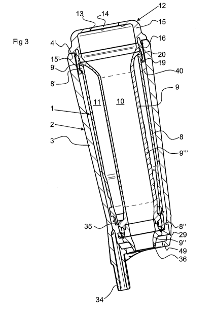
Figs 1 to 4 disclose a teatcup to be attached to the teat of an
animal to be milked. The teatcup comprises a cartridge 1, see
also Fig 5, and a connector 2, see also Fig 6.
The connector 2 comprises a lower base member 3 and a shell 4.
The shell 4 extends from the lower base member 3 and surrounds
a receiving space 5 of the connector 2. When the teatcup is
assembled, the cartridge 1 is received in the receiving space 5 of
the connector as can be seen in Figs 2 and 3.
In the embodiments disclosed, the lower base member 3 and the
shell 4 form one integrated part, and may be made of one piece
of a material, for instance a plastic material.
Throughout the application, the word "upper" indicates a position
closer to the udder of the animal during the milking when the
teatcup is attached to the teat of an animal in comparison to the
word "lower" that indicates a position more remote from the udder
during the milking of the animal.
The teatcup may comprise or be connected to a milk conduit 6,
such as a short milk conduit or a long milk conduit, and to a pulse
conduit 7.
A longitudinal central axis x extends through and along the
teatcup, i.e. through the cartridge 1 and the connector 2. The
longitudinal central axis x may also extend through and along at
least a part of the milk conduit 6 when it is in a rest state as
indicated in Fig 2.
The cartridge 1 comprises an elongated sleeve 8 and a barrel 9.
The elongated sleeve 8 extends in parallel with the longitudinal
central axis x and has an upper end section 8' and a lower end
CA 03075631 2020-03-11
WO 2019/083433 PCT/SE2018/051080
9
section 8". The barrel 9 is pre-mounted in the elongated sleeve 8
and has an inner space 10 for receiving the teat. A pulsation
chamber 11 is formed and enclosed between an inner surface of
the elongated sleeve 8 and an outer surface of the barrel 9.
The cartridge 1 also comprises a head member 12, which
comprises a lip 13 surrounding and defining an opening 14 to the
inner space 10 for the introduction of the teat into the inner space
10.
The head member 12 is provided at the upper end section 8' of
the elongated sleeve 8, and is attached to the barrel 9.
The head member 12 comprises a lip element 15 comprising the
lip 13 and a ring member 16 attached to the lip element 15 and
comprising an engagement element 17, see Fig 4. The
engagement element 17 attaches the head member 12 to the
barrel 9. The engagement element 17 is configured as an annular
protrusion extending inwardly into a groove in the barrel 9 as can
be seen in Fig 4. The groove may be annular extending around
an outer surface of the barrel 9.
The lip element 15 is made of a relatively elastic material,
whereas the ring member 16 is made of a relatively rigid material.
The head member 12 comprises a plurality of locking members
19, in the embodiments disclosed four locking members 19. The
locking members 19 are separated from each other, preferably
equidistantly separated from each other, and are thus uniformly
distributed along the periphery of the head member 12.
The locking members 19 are comprised by the ring member 16
and extends towards the lower end section 8" outside the barrel
9 as can be seen in Fig 4.
CA 03075631 2020-03-11
WO 2019/083433 PCT/SE2018/051080
The elongated sleeve 8 has a flange 20, which may be annular
and extend outwardly and around at the upper end section 8' of
the elongated sleeve 8. Each of the locking members 19 is
gripping the flange 20, and extends beyond the flange 20.
5
Each of the locking members 19 comprises an inwardly extending
portion 21 which comprises an engagement surface 22 turned
away from the lower end section 8". Each of the locking members
19 may comprise or be configured as a hook, as can be seen in
10 Figs 3 and 4.
The flange 20 comprises a lower surface 23 turned towards the
lower end section 8".
Each of the engagement surfaces 22 abuts the lower surface 23
when the locking members 19 of the head member 12 are gripping
the flange 20. The lower surface 23 may comprise a plurality of
surface portions, wherein each of the engagement surfaces 22
abuts a respective one of the surface portions. The surface
portions may lie in the same plane, for instance the same radial
plane, as the lower surface 23, or may be axially displaced with
respect to the lower surface 23.
The flange 20 comprises a plurality of recesses 24, in the
embodiments disclosed four recesses 24, see Figs 5 and 8. The
recesses 24 are separated from each other, preferably
equidistantly separated from each other, and may thus be
uniformly distributed along the periphery of the flange 20.
The flange 20 has an upper surface 25 facing away from the lower
end section 8". The upper surface 25 may be opposite to the
lower surface 23 of the flange 20. The upper surface 25 may
extend in parallel with, or substantially in parallel, with a radial
plane with regard to the longitudinal central axis x.
CA 03075631 2020-03-11
WO 2019/083433 PCT/SE2018/051080
11
Each of the recesses 24 extends through the upper surface 25
and in parallel with the longitudinal central axis x. Each of the
locking members 19 is received in a respective one of the
recesses 24.
Each of the recesses 24 has a tapering shape towards the lower
end section 8', and each of the locking members 19 has a
corresponding tapering shape towards the lower end section 8",
see Figs 5 and 8. The tapering shape of the recesses 24 and the
locking members 19 facilitates introduction of the locking
members 19 into the recesses 24, and contributes to a firm
engagement of each of the locking members 19 in the respective
recess 24.
The barrel 9 comprises an upper end portion 9' located at the
upper end section 8' of the elongated sleeve 8, a lower end
portion 9" located at the lower end section 8" of the elongated
sleeve 8, and a barrel portion 9" extending between the upper
end portion 9' and the lower end portion 9", see Fig 3.
The barrel portion 9" is made of a relatively elastic material,
whereas the upper end portion 9' and the lower end portion 9"
are made of a relatively rigid material.
The upper end portion 9' of the barrel 9 has an abutment surface
27 extending outwardly and turned towards the lower end portion
9" and the lower end section 8", see Fig 4. Also the ring member
16 has an abutment surface 28 turned towards the lower end
section 8" and lying in a common plane with the abutment surface
27 of the upper end portion 9' of the barrel 9, see Fig 8. The
abutment surface 27 of upper end portion 9' and the abutment
surface 28 of the ring member 16 abut the upper surface 25 of the
flange 20, as can be seen in Figs 4 and 8.
In the embodiments disclosed, the barrel portion 9" has, in a rest
state, a triangular cross-sectional shape defining three corner
CA 03075631 2020-03-11
WO 2019/083433 PCT/SE2018/051080
12
portions and three side portions, as is indicated in Fig 2. Each
side portion is straightened and extends between and connects
two of the three corner portion. It should be noted that the barrel
portion 9" also may have any other suitable polygonal cross-
sectional shape or a circular cross-sectional shape.
The lower end portion 9" of the barrel 9 comprises a stop flange
29 extending outwardly, see Figs 3 and 5. The stop flange 29
abuts an end surface of the lower end section 8" of the elongated
sleeve 8, and maintains the axial position of the lower end portion
9" in relation to the elongated sleeve 8.
A protrusion 30 extends downwardly from the end surface of the
lower end section 8" of the elongated sleeve 8. The protrusion 30
may have a dovetail shape, as can be seen in Fig 5. The
protrusion 30 fits into a recess 31 in the stop flange 29 when the
barrel 9 is mounted in the elongated sleeve 8 to prevent the barrel
9 from being rotated and twisted around the longitudinal central
axis x in relation to the elongated sleeve 8. The protrusion 30 and
the recess 31 may thus define the rotary position of the barrel 9
in the elongated sleeve 8. It should be noted that more than one
protrusion 30 and recess 31 may be provided.
In the embodiment disclosed, the elongated sleeve 8 comprises
three openings 33, see Figs 3 and 9, at the lower end section 8".
The openings 33 are distributed, preferably equidistantly
distributed, around the lower end section 8" of the elongated
sleeve 8. Each of the openings 33 permits passage of a pulsating
pressure into and out from the pulsation chamber 11 via a pulse
nipple 34 and the pulse conduit 7. Although the number of
openings 33 could be another than three, it is preferable if the
number of openings 33 is the same as the number of side portions
of the barrel portion 9" of the barrel 9.
The barrel portion 9" comprises a protruding ring 35 projecting
outwardly and extending around the barrel portion 9" in the
CA 03075631 2020-03-11
WO 2019/083433 PCT/SE2018/051080
13
proximity of the lower end portion 9". The protruding ring 35
comprises three straightened portions, which each is axially, or
substantially axially, aligned with a respective one of the side
portions of the barrel portion 9". The protruding ring 35 thus has
a polygonal shape corresponding to the polygonal shape of the
barrel portion 9" above the protruding ring 35. Each of the
straightened portion of the protruding ring 35 is located partly
opposite to a respective one of the openings 33. Furthermore, the
barrel 9, in particular the lower end portion 9", comprises or forms
a milk outlet nozzle 36.
When the cartridge 1 is received in the connector 2, the shell 4
extends from the lower end section 8" to the upper end section 8'
of the elongated sleeve 8. The elongated sleeve 8 is thus
protected by the shell 4. Furthermore, the locking members 19
are located inside and adjacent to an inner surface 40 of the shell
4 when the cartridge 1 is received in the receiving space 5 of the
connector 2. The shell 4 will thus prevent the locking members 19
from moving outwardly and thus from leaving the engagement of
the flange 20.
When the cartridge 1 is received in the receiving space 5 of the
connector 2, only the lip element 15 of the head member 12
extends above and beyond an upper end surface 4' of the shell 4.
The lip element 15 has a lower surface 15" that abuts the upper
end surface 4' of the shell 4 when the cartridge 1 is received in
the connector 2. The abutment of the lower surface 15" against
the upper end surface 4' contributes to seal the receiving space
5 from the environment.
A plurality of coupling members 41 are provided on an outer
surface 42 of the elongated sleeve 8, see Fig 9, and a plurality of
complementary coupling members 43 are provided on the inner
surface 40 of the shell 4 of the connector 2, see Fig 7. Each of
the coupling members 41 form a bayonet coupling with a
CA 03075631 2020-03-11
WO 2019/083433 PCT/SE2018/051080
14
respective one of the complementary coupling members 43 to
permit locking of the cartridge 1 in the connector 2.
A passage 44 is provided between each of the coupling members
41 to permit a respective on of the complementary coupling
members 43 to pass when the cartridge 1 is introduced into the
receiving space 5 of the connector 2 along a direction parallel
with the longitudinal central axis x. The cartridge 1 may thus be
introduced into the connector 2 along said direction until the
coupling member 1 has passed beyond the complementary
coupling member 43 to a final axial position.
Each of the coupling members 41 comprises an upper surface 45
turned away from the lower end section 8" to permit engagement
by the complementary coupling member 43. When the cartridge 1
has reach the final axial position along said direction, it may be
rotated in relation to the connector 2, wherein the upper surface
45 of each coupling members 41 may slide on a lower surface 46
of a respective one of the complementary coupling members 43.
In the embodiments disclosed, each of the coupling members 41
comprises a stop surface 47 extending from the upper surface 45
and being parallel with the longitudinal central axis x. The stop
surface 47 provides or defines the final rotary position of the
cartridge 1 after the rotation of the cartridge 1 around the
longitudinal central axis x in relation to the connector 2.
Furthermore, each of the coupling members 41 comprises a
sloping ramp 48 extending to the upper surface 45 to permit
sliding of the complementary coupling member 43 onto the upper
surface 45. The sloping ramp 48 may facilitate for the upper
surface 45 of the cartridge 1 to reach the lower surface 46 of the
connector 1, and thus the sloping ramp 48 may facilitate the initial
part of said rotation of the cartridge 1 in relation to the connector
2.
CA 03075631 2020-03-11
WO 2019/083433 PCT/SE2018/051080
The connector 2 comprises a bottom flange 49 extending inwardly
towards the longitudinal central axis x, especially radially
inwardly. The flange 49 may engage a corresponding groove in
an upper portion of the milk conduit 6 in order to releasably attach
5 the connector 2 to the milk conduit 6 as can be seen in Fig 2.
The cartridge 1 is assembled by attaching the head member 12
to the barrel 9, wherein the engagement element 17 engages the
groove on the outer side of the barrel 9. The barrel 9, with the
10 head member 12 attached thereto, is then mounted in the
elongated sleeve 8, by means of a suitable tool, so that the stop
flange 29 is pressed beyond the lower end of the elongated sleeve
8. The stop flange 29 then flexes outwardly to lock the stop flange
29 against the lower end of the elongated sleeve 8, wherein the
15 relative rotary positions of the elongated sleeve 8 and the barrel
9 are adjusted to permit the protrusion 30 to engage the recess
31. At the same time the locking members 19 are introduced into
the recesses 24 until the engagement surfaces 22 passes beyond
the lower surface 23 of the flange 20. The locking members 19
will then flex inwardly to permit the engagement surfaces 22 in
order to abut the lower surface 23.
The cartridge 1 may then be mounted in the connector 2 by being
introduced along a direction being parallel to the longitudinal
central axis x. The cartridge 1 is held in a rotary position so that
the complementary coupling members 43 may pass through the
passages 44. When the cartridge 1 cannot be moved any further,
when the milk outlet nozzle 36 abuts an inner inlet surface of the
milk conduit 6, the cartridge 1 is rotated in relation to the
connector 2, wherein the lower surface 46 of the complementary
coupling members 43 will slide on the sloping ramp 48 and then
on the upper surface 45 until the complementary coupling
member 43 at a final position reaches the stop surface 47. When
the cartridge 1 has reach the final position in the connector 2, the
complementary coupling member 43 thus abuts the upper surface
and the stop surface 47 of the coupling member 41. The milk
CA 03075631 2020-03-11
WO 2019/083433 PCT/SE2018/051080
16
outlet nozzle 36 is in this final position pressed against the inner
inlet surface of the milk conduit 6 as can be seen in Fig 2.
The present invention is not limited to the embodiments disclosed
and described herein, but may be modified and varied within the
scope of the following claims.
It should be noted that the sloping ramp 48 could as an alternative
be provided on the complementary coupling member 43 and then
extend to the lower surface 46.
Furthermore, the stop surface 47 could as an alternative be
provided on and extend downwardly from the lower surface 46 of
the complementary coupling member 43.
The stop surface 47 does not have to extend all the way from the
upper surface 45 or from the lower surface 46, but may start at a
distance from any one of this surfaces 45, 46.
The complementary coupling member 43 has in the embodiments
disclosed a rectangular shape seen in a radial direction. It should
be noted that the complementary coupling member 43 may
instead have other shapes, such as a circular shape.