Note: Descriptions are shown in the official language in which they were submitted.
- 1 -
FOUR-EDGED DRILL
FIELD OF INVENTION
The invention relates to a four-edged drill, in
particular to a deep-hole drill, for cutting
difficultly cuttable cast and light metal materials of
the kind used in engine construction.
BACKGROUND
Such materials can only be processed efficiently given
the ability to adjust not only the material of the
drill, but also the geometry to the cutting task so as
to yield adequate tool lives and paths. US 5,173,014
proposes a spirally grooved, four-edged drill, which
for drilling a cast iron engine block has two long main
cutting edges arranged in a point symmetrical manner
relative to the axis of rotation, which each extend
from a chamfered, outer circumferential cutting corner
to a chisel edge in the middle of the drill tip, and
two short main cutting edges arranged in a point
symmetrical manner relative to the axis of rotation,
which each extend from a chamfered, outer
circumferential cutting corner until into the drill
core, but not as far as the middle of the drill tip.
Each of the main cutting edges is continuously straight
in design, and lies in front of a diametral plane of
the drill as viewed in the rotational or cutting
direction of the drill. The cutting surfaces forming
the main cutting edges each border a primary chip
removal trough that is outwardly bent at an
inclination, which empties into an allocated, spirally
running chip groove. Each cutting edge has a rake angle
of 0 from its outer peripheral cutting corner up to
its inner end. Provided to the side of the chisel edge
are secondary chip removal grooves, which each extend
from the primary chip removal groove of a short main
Date Recue/Date Received 2021-09-10
- 2 -
cutting edge, and proceed outwardly at an inclination
as far as the primary chip removal groove of a long
main cutting edge. These secondary chip removal grooves
incorporate the outlet openings of two cooling
lubricant supply channels.
Due to the long main cutting edges that extend as far
as the middle of the drill tip, the drill proposed in
US 5,173,014 allows drilling into solid materials.
However, the chisel edge that connects the two long
main cutting edges has no cutting effect, as in a
conventional double-edged spiral drill. It only exerts
pressure and friction on the workpiece, and for this
reason basically impedes drilling into solid materials.
The chips scraped from a workpiece by the chisel edge
flow through the secondary chip removal grooves and
free surfaces of the long main cutting blades into the
primary chip removal grooves and chip grooves. Starting
at a sufficiently large feed path, both the two long
main cutting edges and the two short main cutting edges
cut into a workpiece independently of each other,
wherein the chip width of the chips generated by the
main cutting edges depends on the length of the
respective main cutting edge. The chip removal load is
thus distributed among four cutting edges, wherein the
load placed on the long main cutting edges is greater
than that placed on the short main cutting edges, as a
result of which the long main cutting edges can close
at an earlier point. At a high feed rate, the larger
chip cross section of the wider chips arising at the
long main cutting edges can easily lead to chip
congestion, in particular while deep drilling.
Proceeding from the drill known from US 5,173,014, the
object of the invention is to provide a four-edged
drill, in particular a deep-hole drill, for cutting
difficultly cuttable cast materials and light metal
Date Recue/Date Received 2021-09-10
- 3 -
materials used in motor construction, which even at
high feed rates is distinguished by a high stability
under load and an improved chip removal.
DESCRIPTION
This object is achieved by drills according to the
present invention.
A four-edged (deep-hole) drill according to the
invention has a drill tip with two longer or (in the
following:) long main cutting edges arranged in a point
symmetrical manner relative to the axis of rotation,
which each extend from an outer circumferential cutting
corner to a chisel edge in the middle of the drill tip,
and two shorter or (in the following:) short main
cutting edges arranged in a point symmetrical manner
relative to the axis of rotation, which each extend
from an outer circumferential cutting corner in the
direction of, but not as far as, the middle of the
drill tip. According to the invention, each long main
cutting edge has an outer partial cutting edge
extending from the cutting corner up to a step or (in
the following:) a shoulder, and an inner partial
cutting edge extending from the shoulder as far as the
chisel edge. The inner partial cutting edges have a
greater cutting height than the outer partial cutting
edges and the two short main cutting edges.
As opposed to the tool discussed at the outset, the
long main cutting edges in a drill according to the
invention are divided into outer partial cutting edges
and inner partial cutting edges, wherein the inner
partial cutting edges lie higher than the outer partial
cutting edges as viewed in an axial or feed direction
of the drill, i.e., cut into a workpiece to be
processed before the outer partial cutting edges and
the two short main cutting edges. The inner partial
Date Recue/Date Received 2021-09-10
- 4 -
cutting edges thus form a double-edged tip downwardly
offset from the outer partial cutting edges and the
short main cutting edges in an axial or feed direction.
The higher inner partial cutting edges can thus also be
referred to as pre- and solid drilling edges, which
allow the drill to cut into solid materials, while the
outer partial cutting edges and the short main cutting
edges can also be referred to as reaming cutting edges,
which are used to bore out the hole generated by the
inner partial cutting edges.
On the one hand, the higher inner partial cutting edges
lead to a self-centering, which allows the drill to cut
into a solid material while drilling a workpiece
without running askew. Predrilling is thus not
required. This results in a good dimensional and
geometrical accuracy of the hole. As opposed to
conventional single-lip deep-hole drills, for example,
no guide is thus required in the drill according to the
invention.
On the other hand, dividing the long main cutting edges
results in a load distribution on the inner and outer
partial cutting edges. The higher inner partial cutting
edges lie in the area of the drill core in which the
chip volume is lower while drilling a workpiece than in
the area outside of the drill core. Apart from the two
outer partial cutting edges, the two short main cutting
edges are formed in the outer drill area in which the
chip volume is larger. As a result, the chip load in
the area of the main cutting edges that cut to a
nominal diameter, i.e., up to the cutting edge corners,
is distributed to four cutting edges, making it
possible to minimize the chip load per cutting edge,
and hence also the wear, in particular the cutting
corner wear.
Date Recue/Date Received 2021-09-10
- 5 -
Dividing the long main cutting edges into the outer and
inner partial cutting edges also provides the option of
correspondingly optimally adjusting the inner and outer
partial cutting edges to the various chipping
conditions independently of each other by
correspondingly establishing the cutting wedge angle,
correcting the cutting edges, sharpening the chisel
edge and taking similar measures.
Another result of dividing the long main cutting edges
into the outer and inner partial cutting edges is that
two narrower chips arise instead of one broad chip
while drilling a workpiece, which collide with each
other during removal into the chip groove chambers of
the drill, and can therefore break. This yields a good
chip removal.
In sum, a (deep-hole) drill can be manufactured
according to the invention that is characterized by a
good centering, a high concentricity quality, a high
smoothness, and a high service life. A drill according
to the invention is thus also suitable in particular
for generating deep holes in difficultly cuttable cast
or light metal materials of the kind used in engine
construction.
The cutting height difference between the inner partial
cutting edges and the outer partial cutting edges of
the long main cutting edges achieved by the downward
offset can range from 0.02 to 0.1 times, in particular
0.04 to 0.08 times, the nominal diameter of the drill,
i.e., be very small relative to the nominal diameter,
so as to counter a diminished stability of the drill.
Advantageous or preferred further developments are also
described herein.
Date Recue/Date Received 2021-09-10
- 6 -
Comprehensive tests with varyingly ground drill tips
have shown that a good stability under load can be
achieved if the outer partial cutting edges of the long
main cutting edges and/or short main cutting edges that
run in the direction of the middle of the drill from
outer circumferential cutting corners end outside of
the core diameter of the drill. The drill core cross
section is retained as a result, so that a high service
life can be ensured. In addition, the load placed on
the outer partial cutting edges of the long main
cutting edges and/or the short main cutting edges can
be limited. The drill configuration allows the core
diameter to be expanded to 0.4 to 0.6 times, in
particular about 0.5 times, the nominal diameter of the
drill, which contributes to a high stability and
service life.
If the shorter main cutting edges are longer than the
outer cutting edges, i.e., the shorter main cutting
edges extend closer to the core diameter of the drill
than the outer partial cutting edges, drilling a
workpiece will result in an uneven load on the outer
partial cutting edges and shorter main cutting edges,
thereby enabling a reduction in the tendency of the
drill to rattle while the short main cutting edges and
outer partial cutting edges of the long main cutting
edges penetrate into a workpiece, and thus an increase
in the smoothness of the drill.
Point thinning makes it possible to positively
influence the cutting characteristics of the inner
partial cutting edges and/or the chisel edge of the
drill. In this way, the progression of the inner
partial cutting edges can be corrected via point
thinning with the aim of making them longer and sharper
edged than would be the case without point thinning, as
a result of which the load can be distributed and
Date Recue/Date Received 2021-09-10
- 7 -
diminished over a larger length. In particular, the
inner partial cutting edges can be corrected in such a
way as to run at an obtuse angle to the outer partial
cutting edge of the same main cutting edge. The chisel
edge can be point thinned independently thereof, so as
to keep it as short as possible and give it sharp
edges, making it possible to also reduce the forces in
the area of the chisel edge and allowing a pinpoint
boring into a solid material. Point thinning also
yields an enlargement of the chip groove volume, which
facilitates a good chip removal while drilling a
workpiece.
For example, the point thinning sections that empty
into the outer circumferential chip grooves of the
drill for correcting the inner partial cutting edges
and shortening the chisel edge can have a roughly V-
shaped cross section with rounded base, the opening
angle of which lies within a range of 750 to 85 , e.g.,
at 80 . Good results can be achieved in particular if
the point thinning sections each extend at an angle of
between 30 and 45 to a cross sectional plane of the
drill (a plane transverse to the axis of rotation of
the drill). Such large point thinning sections
extending from the core to the outer circumference of
the drill facilitate a good chip removal. For example,
the point thinning sections that correct the inner
partial cutting edges can each extend at an angle of
about 40 , and the point thinning sections that shorten
the chisel edge can each extend at an angle of about
35 to a cross sectional plane of the drill.
The drill can further be point thinned in the core
regions that border the short main cutting edges. These
point thinning sections with a cross section shaped
like a flat trough, for example, can each extend at an
angle of 40 to 50 , in particular of about 48 , to a
Date Recue/Date Received 2021-09-10
- 8 -
cross sectional plane of the drill from the core region
that borders a short main cutting edge as far as the
outer circumference of the drill.
The ground drill tip section can be simplified by
having the outer partial cutting edges of the long main
cutting edges and the short cutting edges have the same
tip angle. Analogously thereto, the outer partial
cutting edges and inner partial cutting edges of the
long main cutting edges can have the same tip angle.
For example, the tip angles can lie within a range of
140 to 150 , in particular at 145 .
The two inner partial cutting edges can be arranged at
the same cutting height. Analogously thereto, the outer
partial cutting edges can be arranged relative to each
other at the same cutting height, just as the short
main cutting edges relative to each other.
However, the short main cutting edges can also have a
defined cutting height difference in relation to the
outer partial cutting edges of the long main cutting
edges, in particular a larger cutting height. For
example, the cutting height difference can lie within a
range of 0.01 to 0.03 mm, in particular at 0.02 mm. A
defined cutting height difference makes it possible to
reduce the tendency of the drill to rattle as the short
main cutting edges and outer partial cutting edges of
the long main cutting edges penetrate into a workpiece,
and thus increase the smoothness of the drill.
The ground drill tip section is further simplified by
providing a straight-line design to the short main
cutting edges, the inner partial cutting edges of the
long main cutting edges and the outer partial cutting
edges of the long main cutting edges.
Date Recue/Date Received 2021-09-10
- 9 -
A high cutting edge stability is ensured by arranging
each main cutting edge, i.e., the inner and outer
partial cutting edges of the long main cutting edges
and the short main cutting edges in front of a
diametral plane of the drill as viewed in the cutting
direction.
A high cutting edge stability is further achieved when
the rake angle of the main cutting edges is greater
than or equal to 00.
In order to achieve a high cutting quality, each
shoulder can be axially and/or radially relief ground.
This measure enables a pinpoint boring into solid
material.
The drill according to the invention is preferably
designed with straight grooves. Chip grooves running
along a straight line are easy, and thus efficient, to
produce. The ground drill tip section discussed above
ensures a good chip removal, despite the straight
running chip grooves.
The removal of chips or chip fragments can be further
improved by supplying a cooling lubricant into the chip
grooves of the drill. In this regard, the drill can
have an interior cooling lubricant supply system with
outlet openings that lie in the area of the free
surfaces, in particular the secondary free surfaces, of
the main cutting edges.
A drill according to the invention can be fabricated
out of one piece, i.e., be monolithic in design.
Alternatively thereto, the drill can be composed of
several components. Precisely longer drills, e.g.,
deep-hole drills, can be efficiently manufactured
because the four main cutting edges are ground into a
Date Recue/Date Received 2021-09-10
- 10 -
cutting head attached to a shank. In this case, the
cutting head and shank can be made out of different
materials. For example, the cutting head can consist of
solid carbide, which ensures a good stability under
load. By contrast, the shank can consist of an
inexpensive and stable steel material.
A drill according to the invention will be described in
more detail below based on an exemplary embodiment
shown in the drawings. Shown on:
Fig. 1 is a front view of a drill tip of a four-cutting
edged deep-hole drill;
Figs. 2 to 4 are side views of the drill tip from Fig.
1;
Figs. 5 and 6 are perspective side views of the drill
tip from Fig. 1;
Fig. 7 is a front view of the drill tip rotated by 900
relative to the front view from Fig. 1;
Figs. 8 and 9 are side views of the drill tip from Fig.
7;
Fig. 10 is a perspective side view of the drill tip
from Fig. 7;
Fig. 11 is a side view of a blank of the four-edged
deep-hole drill according to the invention;
Figs. 12 to 15 is a respective side view and top view
of a shank, a retaining ring and a clamping sleeve of
the four-edged drill; and
Date Recue/Date Received 2021-09-10
- 11 -
Fig. 16 is a side view and a top view of a cutting head
blank of the four-edged drill.
In the exemplary embodiment shown on the figures, the
drill is designed as a four-edged deep-hole drill 10.
Fig. 11 shows a side view of a blank of the deep-hole
drill 10, which consists of a shank 13, the cutting
head 12 soldered to the shank 13, a clamping sleeve 14
positively joined to the shank 13, and a retaining ring
15 that fixes the shank 13 to the clamping sleeve 14
via jacketing and soldering. The shank 11, clamping
sleeve 14 and retaining ring 15 are shown in more
detail on Figs. 12 to 15. A blank of the cutting head
11 is shown in more detail on Fig. 16. As shown on
Figs. 11, 12 and 16, the shank 13 and cutting head 12
are each designed with straight grooves.
In order to connect the cutting head 12 with the shank
13, the end of the shank 13 on the cutting head side
has a V-shaped notch 16 referred to as a soldering
prism, into which a chisel tip 17 formed on the shank-
side end of the cutting head 12 is positively
accommodated and materially connected with the shank 13
through soldering.
As shown by the top views on Figs. 12 and 13, the shank
13 has four webs 18 arranged at an angular distance of
90 , between which is formed a respective chip groove
19 running along a straight line parallel to the axis
of rotation 1.
Corresponding to the number of chip grooves 19, the
clamping sleeve 14 shown on Fig. 15 has four axial,
roughly quadrantal segment-shaped projections 21, which
are each positively inserted into one of the chip
grooves 19 so as to connect the shank 13 with the
Date Recue/Date Received 2021-09-10
- 12 -
clamping sleeve 14. Reference number 14a denotes a
clamping surface over which the clamping sleeve 14 can
be non-rotatably clamped in a chuck (not shown).
The retaining ring 15 shown on Fig. 14 rests on the
interface created in this way between the clamping
sleeve 14 and shank 13. In order to fix the shank 13 on
the clamping sleeve 14, the retaining ring 15 is
soldered with the shank 13 and clamping sleeve 14.
The cutting head 12 is fashioned out of the cutting
head blank 24 shown on Fig. 16. The V-shaped dashed
line marks the chisel tip 17 of the cutting head 12 to
be attached to the V-shaped notch of the shank 16.
Analogously to the shank 13, the cutting head 12 has
four webs 22 arranged at an angular distance of 900,
between which is formed a respective essentially V-
shaped chip groove 23 running along a straight line
parallel to the axis of rotation 1 (see top view on
Fig. 16).
In the state attached to the shank 13 (see Fig. 11),
the chip grooves 19 of the shank axially adjoin the
chip grooves 23 of the cutting head 12. As evident from
Fig. 11, the cutting head 12 has a somewhat larger
diameter than the shank 13.
Shown by dashed lines on Figs. 12 and 16 is an interior
cooling lubricant supply system comprised of a central
main channel 25 that extends through the clamping
sleeve 14 and shank 13 as far as the cutting head 12,
and, corresponding to the number of webs 22 or chip
grooves 23, four branch channels 26, which branch away
from the main channel 25 immediately after the joint
between the shank 13 and cutting head 12, and outlet
openings 27, which lie in the area of the subsequently
described free surfaces of the four main cutting edges
Date Recue/Date Received 2021-09-10
- 13 -
of the cutting head 12. The main channel 25 and branch
channels 26 each run along a straight line (holes).
Figs. 1 to 10 show how the drill tip 11 of the four-
edged cutting head 12 is ground, which in the state
shown on Fig. 11 is done on the end faces of the
cutting head 12. Figs. 1 to 10 thus present grinding
instructions for grinding the drill tip 11 of the
cutting head 12.
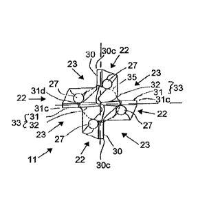
As shown on Fig. 1, four main cutting edges 33 (a main
cutting edge 33 per web 22) are formed on the drill tip
11. In the exemplary embodiment shown, the four main
cutting edges 33 comprise two longer or (in the
following:) long main cutting edges 33 arranged in a
point symmetrical manner relative to the axis of
rotation 1, which each extend from an outer
circumferential cutting corner 31c as far as a chisel
edge 34 (see Fig. 7) in the middle of the drill tip 11,
and two shorter or (in the following:) short main
cutting edges 30 arranged in a point symmetrical manner
relative to the axis of rotation, which each extend
from an outer circumferential cutting corner 30c in the
direction of, but not as far as, the middle of the
drill tip 11. According to the invention, each long
main cutting edge 33 has an outer partial cutting edge
31 extending from the cutting corner 31c as far as a
step or (in the following:) a shoulder 31d (see Fig. 2)
and an inner partial cutting edge 32 extending from the
shoulder 31d as far as the chisel edge 34.
As viewed in the axial or feed direction of the deep-
hole drill 10, the inner partial cutting edges 32 have
a greater cutting height than the outer partial cutting
edges 31 and the two short main cutting edges 30. The
higher inner partial cutting edges 32 can thus also be
referred to as pre- and solid drilling edges, which
Date Recue/Date Received 2021-09-10
- 14 -
allow the deep-hole drill to cut into solid materials,
while the outer partial cutting edges 31 and the short
main cutting edges 30 can also be referred to as
reaming cutting edges, which are used to bore out the
hole generated by the inner partial cutting edges 32 to
the nominal diameter of the deep-hole drill.
The higher inner partial cutting edges 32 lie in the
area of the drill core 35 of the deep-hole drill 10,
while the outer partial cutting edges 31 and the two
short main cutting edges 30 lie outside of the core 35.
The outer partial cutting edges 31 and the short main
cutting edges 30 thus end radially outside of the core
35 or¨viewed from the outside in¨in front of the core
35. In the exemplary embodiment shown, the diameter of
the core 35 measures about 0.4 to 0.6 times, in
particular about 0.5 times, the nominal diameter of the
deep-hole drill.
The cutting height difference Ax between the inner
partial cutting edges 32 and the outer partial cutting
edges 31 achieved by the shoulder 31d lies within a
range of 0.02 to 0.1 times, in particular of 0.04 to
0.8 times, the nominal diameter of the deep-hole drill
10. As evident from Fig. 2, the shoulder 31d is axially
relief ground. For example, the angle indicated with E
measures 90 .
A secondary cutting edge that runs along a straight
line and is not described here in any greater detail
adjoins each of the cutting corners 31c, 30c in the
usual manner.
As shown on Figs. 1 to 10, the outer partial cutting
edges 31, the inner partial cutting edges 32 and the
short main cutting edges 30 are each straight in
design.
Date Recue/Date Received 2021-09-10
- 15 -
In addition, the two outer partial cutting edges 31,
the inner partial cutting edges 32 and the short
cutting edges 30 are arranged at the same point angles.
In the exemplary embodiment, the point angles of the
outer partial cutting edges 31, inner partial cutting
edges 32 and short main cutting edges 30 indicated with
031, 032, 030 on Fig. 2 and Fig. 8 lie within a range of
140 to 150 , in particular at 145 .
In addition, the two inner partial cutting edges 32 are
arranged at the same cutting height. In addition, the
outer partial cutting edges 31 are arranged at the same
cutting height, and the short main cutting edges 30 are
arranged at the same cutting height. In the exemplary
embodiment shown, however, the short main cutting edges
30 have a defined cutting height difference relative to
the outer partial cutting edges 31, which can lie
within a range of 0.01 to 0.03 mm, in particular at
0.02 mm.
In addition, the inner partial cutting edges 32, the
outer partial cutting edges 31 and the short main
cutting edges 30 lie in front of a diametral plane of
the deep-hole drill 10 viewed in the cutting direction,
i.e., they cut "before the middle".
The rake angle not indicated on the figures for all
main cutting edges, i.e., the inner partial cutting
edges 32, the outer partial cutting edges 31 and the
short main cutting edges 30, is equal to or greater
than 0 in the exemplary embodiment shown.
On Fig. 7, reference numbers 31a, 32a and 30a indicate
primary free surfaces, and reference numbers 31b, 32b
and 30b indicate secondary free surfaces relative to
Date Recue/Date Received 2021-09-10
- 16 -
the outer partial cutting edges 32, the inner cutting
edges 32 or the short main cutting edges 30.
As further shown on Fig. 7, the outlet openings 27 of
the four branch channels 26 of the aforementioned
interior cooling lubricant supply system each lie in
the area of the free surfaces, in particular in the
area of the secondary free surfaces, of an allocated
main cutting edge.
Visible on Figs. 1 to 10 are grinded point thinning
sections 40, 41, 42, which result in a shortening of
the chisel edge 34 (see Fig. 7), and a correction of
the inner partial cutting edges 32 or of the core area
lying in front of a short main cutting edge 30 in the
sectional or rotational direction. Visible on Fig. 1 or
7 are the point thinning sections grinded into the
drill tip 11. The point thinning section 41 corrects
the inner partial cutting edge 32, so that the inner
partial cutting edge 32 in the exemplary embodiment
shown runs at an angle to the outer partial cutting
edge 32 of the same main cutting edge. The point
thinning section 32 causes the core region lying in
front of a short main cutting edge 30 in the rotational
or sectional direction to be grinded in.
The point thinning sections are grinded in using
grinding wheels (not shown). The cross sectional
contour of each point thinning section is thus
determined by the shape of the respectively used
grinding wheel. Figs. 6, 9 and 10 describe the grinded
in portions, wherein Figs. 5, 6 and 10 show the deep-
hole drill 10 in a position and alignment in which the
grinded in portions extend in a direction perpendicular
to the leaf level, while Figs. 3, 4 and 9 show the
angle of inclination a40, a41, a42 Of the grinded in
Date Recue/Date Received 2021-09-10
- 17 -
portions relative to a plane perpendicular to the
rotational axis 11 of the deep-hole drill 10.
In particular, Figs. 3 and 5 show a grinded in portion
for generating the point thinning section 40 that
shortens the chisel edge 34, Figs. 4 and 6 show a
grinded in portion for generating the point thinning
section 41 that corrects the inner partial cutting edge
31, and Figs. 9 and 10 show a grinded in portion for
generating the point thinning section 42. The
transverse contours of the grinded in portions or point
thinning sections 40, 41, 42, and thus the shapes of
the respectively used grinding wheels , are discernible
on Figs. 5, 6 or 10.
As shown on Figs. 5, 6 and 10, the point thinning
sections 40, 41 or 42, which each empty into an
allocated chip groove 23 of the deep-hole drill 10,
have a roughly V-shaped cross section with a rounded
base, the opening angle of which measures 1340 or P41
(see Figs. 5, 6), or a cross section in the form of a
flat trough (see Fig. 10). In the exemplary embodiment
shown, the opening angle 140 or P41 lies within a range
of 750 to 85 , e.g., at 80 .
In the exemplary embodiment shown, the aforementioned
angles of inclination a40, a41, a42 relative to a plane
perpendicular to the axis of rotation 11 of the deep-
hole drill 10 lie between 30 and 50 , wherein the
angle of inclination a40 can measure 35 , the angle of
inclination a41 can measure 40 , and the angle of
inclination a42 can measure 48 , for example.
Of course, a drill according to the invention can be
modified from the exemplary embodiment described above.
Date Recue/Date Received 2021-09-10
- 18 -
For example, the point thinning section described based
on Figs. 1 to 10 can basically be used for drills of
any length. Therefore, a drill according to the
invention is not necessarily limited to a deep-hole
drill.
Contrary to the exemplary embodiment described, a drill
according to the invention, for example a deep-hole
drill, can further be made out of a single piece, i.e.,
have a monolithic design.
In addition, a drill according to the invention, for
example a deep-hole drill, can be spirally grooved.
Contrary to the described exemplary embodiment, the
webs 22 (i.e., the chip grooves 23 or the main cutting
edges 30, 33) can be arranged at angular distances
different from 90 . Diametrically opposing main cutting
edges 33 or 30 can here be arranged in a point
symmetrical manner.
In the simplest case, a straight-grooved, four-edged
drill, in particular a deep-hole drill, constitutes an
separate aspect of the present invention.
In one aspect of the present invention, there is
provided a straight-grooved drill, in particular a
deep-hole drill, with a drill tip having four main
cutting edges. As opposed to the drill from US
5,173,014 discussed at the outset, this type of a
drill, in particular a deep-hole drill, can be
manufactured more easily and cost-effectively. Some
embodiments of four-edged drills of the present
invention can have additional configuration features as
described herein.
Date Recue/Date Received 2021-09-10
- 19 -
For example, some embodiments of the present invention
can involve the four main cutting edges of the drill
being comprised of two long main cutting edges arranged
in a point symmetrical manner relative to the axis of
rotation, which each extend from an outer
circumferential cutting corner as far as a chisel edge
in the middle of the drill tip, and two short main
cutting edges arranged in a point symmetrical manner
relative to the axis of rotation, which each extend
from an outer circumferential cutting corner in the
direction of the middle of the drill tip.
In some embodiments of the present invention, the four
main cutting edges of the drill can define a tip
downwardly offset in the axial direction in the core.
For example, the tip can be achieved by having each
long main cutting edge having an outer partial cutting
edge extending from the cutting corner as far as a
shoulder and an inner partial cutting edge extending
from the shoulder as far as the chisel edge, which has
a larger cutting height than the outer partial cutting
edge and the short main cutting edges.
In some embodiments of the present invention, a
respective outlet opening for cooling lubricant can be
allocated to the four main cutting edges, which lies in
back of a respective main cutting edge in the area of
the free surface in the rotational or cutting
direction.
Date Recue/Date Received 2021-09-10