Note: Descriptions are shown in the official language in which they were submitted.
CA 03075811 2020-03-12
WO 2019/070875
PCT/US2018/054197
EVAPORATOR WITH INTEGRATED HEAT RECOVERY
[0001] The
disclosure relates to recovery of heat in an evaporator that
generates vapor from an operating fluid for use in Rankine cycle systems, and
more specifically to integration of heat exchangers for recovery of thermal
energy
in such systems into a compact, thermally efficient and cost effective
assembly.
BACKGROUND
[0002] The
Rankine cycle is the fundamental operating cycle of all power
plants where an operating fluid is continuously evaporated and condensed. A
closed Rankine cycle system includes a boiler or evaporator for the
evaporation
of an operating fluid, a turbine (or other expander) fed with the vapor to
drive a
generator or other load, a condenser for condensing the exhaust vapors from
the
turbine back to liquid, and a pump for recycling the condensed fluid to the
boiler/evaporator. Operating fluids for Rankine cycle systems include water
and
organic refrigerants such as R-245fa or R134a. Selection of operating fluid
depends mainly on the temperature range at which the Rankine cycle system will
operate, with organic refrigerants best suited to lower operating temperatures
and water/steam being best suited for higher operating temperatures. Low
operating temperatures may prevail in a waste heat recovery application, while
low operating temperatures may be desirable in some small-scale systems
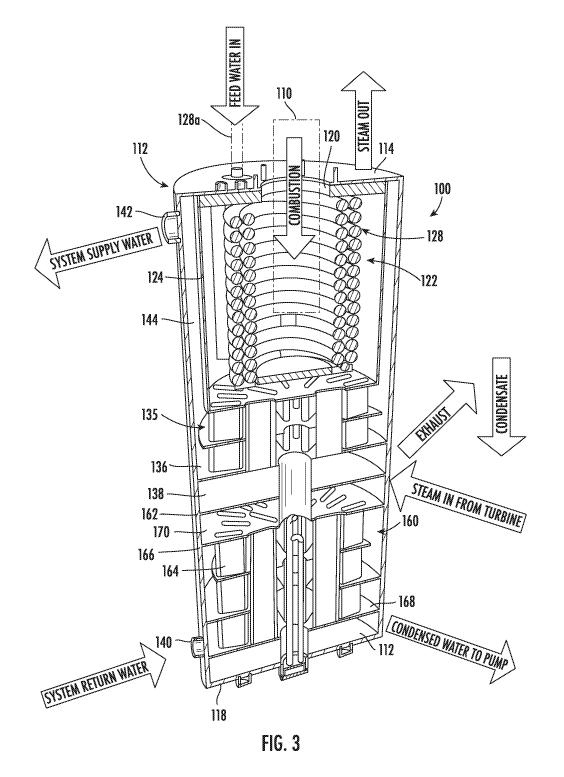
configured for use in residential or small business structures. High operating
temperatures can result in greater efficiency, but present issues of heat
containment and recovery. The division between low operating temperatures
and high operating temperatures is generally about 300 F(148 C) -
350 F(177 C).
[0003] Steam
is used for a wide variety of processes and is commonly
employed as an operating fluid in Rankine cycle systems to convert thermal
energy into mechanical work, which can be used to generate electricity. The
most common way of generating steam is to combust fuel to release heat, which
is transferred to water in a heat exchanger which may be referred to as a
boiler.
1
CA 03075811 2020-03-12
WO 2019/070875
PCT/US2018/054197
Steam boilers typically separate the water into channels or tubes to expand
the
surface area and enhance transfer of heat to the water. Many steam boilers
employ arrangements to recover heat from the exhaust gasses after the gasses
have been used to generate steam. Boilers commonly employ housings and
insulation to contain the heat from combustion and focus the heat on tubes
containing the water. Different arrangements of steam tubes are employed to
enhance heat transfer from the hot combustion gasses to the water.
[0004] Steam
can be generated for delivery at temperatures ranging from
212 F (100 C) to temperatures above 900 F (500 C). Steam may form at
temperatures below 212 F (100 C) in low pressure environments, but may have
limited utility. Low
temperature "saturated" steam is preferred for heating
applications, while high temperature "superheated" steam is preferred for
power
generation and turbines. Superheated steam is steam at a temperature higher
than its vaporization (boiling) point at the absolute pressure where the
temperature is measured. It will be apparent that generating superheated steam
at temperatures above 350 F requires a higher intensity of heat than
generating
low temperature saturated steam. The concentrated heat necessary to generate
superheated steam for use in a turbine creates challenges in terms of heat
containment and recovery when compared to lower temperature systems. For
example, exhaust gasses leaving a combustion chamber where superheated
steam is generated will be at least as hot as the steam, meaning that
significant
energy must be recovered from the exhaust gasses to maintain efficiency of the
system. Heat lost by conduction and radiation can damage sensitive system
components and surrounding materials, and represents potential system
inefficiency.
[0005] In
systems that employ steam to generate electricity, superheated
steam is delivered to an expander such as a steam turbine. As the steam
passes through the turbine, it delivers motive force to turn a generator, and
leaves the turbine as steam at a lower temperature and pressure. After passing
through the expander, steam is cooled and condensed back to liquid water in a
heat exchanger dedicated to this purpose called a "condenser." This liquid
water
2
CA 03075811 2020-03-12
WO 2019/070875
PCT/US2018/054197
is then pumped back into the steam generator to complete the cycle. The
condenser may be configured to deliver the heat recovered from the turbine
exhaust to another system, such as domestic hot water, hydronic heating
systems, or an evaporative cooling system such as an absorption chiller. Heat
is
also commonly recovered from the exhaust gasses leaving the steam generator.
[0006] It is
common for combined heat and power systems to employ
three heat exchange assemblies: the heat source/steam tube exchanger; the
condenser; and an exhaust gas heat recovery heat exchanger. These three heat
exchangers are typically provided as separate assemblies, which occupy
significant space, is inefficient in terms of manufacturing cost, increases
the
number of potential points of failure, and allows heat leakage by radiation
and
conduction to the surrounding environment. Large scale steam driven electric
generators are typically situated in dedicated purpose-built structures, and
are
operated by trained personnel. Small scale micro CHP equipment designed for
installation in the mechanical room of a home or a small business must be
extremely compact and release small amounts of heat to the surrounding
environment.
[0007] Small
scale or "micro" combined heat and power (CHP) systems
are being developed for use in residential structures and small businesses.
These systems generate steam and employ a steam turbine to generate
electricity, with heat recovered from exhaust gasses and the condenser for use
by the home or business owner. Micro CHP systems provide back-up power
generation, low cost electricity, and heat in a single system, making them
attractive alternatives to conventional heating systems. Further, micro CHP
systems can be connected to communicate with each other and provide
coordinated response to peak power demand or load absorption when renewable
sources place excess power on the grid.
[0008] There
is a need for a compact and cost effective arrangement of a
steam generator, turbine, and heat exchangers suitable for micro CHP systems
to be installed in residential and small business structures.
3
CA 03075811 2020-03-12
WO 2019/070875
PCT/US2018/054197
[0009] There
is a need for a compact and thermally efficient arrangement
of heat exchangers for use in micro CHP systems which limit heat released to
the
surrounding environment.
SUMMARY OF THE INVENTION
[0010] An
evaporator with integrated heat recovery incorporates a vapor
tube in a combustion chamber surrounded by a water jacket. The water jacket is
in fluid communication with an exhaust gas heat exchanger. Coolant circulates
through the exhaust gas heat exchanger to recover heat from exhaust gasses
leaving the combustion chamber and then circulates through the water jacket
surrounding the combustion chamber to recover heat not delivered to the
operating fluid.
[0011] A
housing of the evaporator surrounds the combustion chamber
and exhaust gas heat exchanger and defines an outer boundary of the water
jacket. The combustion chamber may be cylindrical and the water jacket may
include an annular space surrounding the combustion chamber. The combustion
chamber may have a vertical orientation, with an opening for a fuel burner at
a
top of the combustion chamber and outlets for combustion gasses at a bottom of
the combustion chamber. The vapor tube includes an inlet end for receiving
operating fluid and an outlet end through which vapor-phase operating fluid
leaves the vapor tube. The inlet and outlet ends of the vapor tube may be
located outside the evaporator housing. A fuel burner is arranged to release
heat
and hot combustion gasses into the combustion chamber, where heat is
transferred to operating fluid in the vapor tube. The combustion chamber may
include a thermal barrier at least partially surrounding the vapor tube.
[0012] The
exhaust gas heat exchanger includes exhaust tubes that
receive heated combustion gasses from the combustion chamber. The exhaust
tubes are surrounded by coolant to recover heat from the exhaust gasses that
has not been transferred to the operating fluid. Coolant enters the housing
and
circulates first through the exhaust gas heat exchanger and then through the
coolant jacket before leaving the housing.
4
CA 03075811 2020-03-12
WO 2019/070875
PCT/US2018/054197
[0013] The
disclosed vapor tube is one form of a heat exchanger to
transfer heat generated in the combustion chamber to operating fluid to
generate
vapor, but other forms of heat exchanger for this purpose are compatible with
the
disclosed evaporator. The vapor tube may be a continuous length of tubing
formed into a helical coil surrounding a cylindrical space. A fuel combustor
may
be arranged to release heat and hot combustion gasses into the cylindrical
space
surrounded by the vapor tube. The vapor tube may include fins on its outside
surface to expand the surface area for exchange of heat. The vapor tube may be
a continuous length of tubing formed into two concentric helical coils, with a
first
coil including an operating fluid inlet and the second coil including a vapor
outlet,
the coils being connected at their lower ends. The helical coils may have a
vertical orientation and be concentric within a cylindrical combustion
chamber.
The helical coils may be wound in opposite directions and have a downward
pitch from an inlet/outlet end outside the evaporator housing to their
connected
lower ends. The rings of one helical coil may be radially spaced from the
rings of
the other helical coil and may cross each other at an acute angle when viewed
from a radial direction. The rings of each helical coil are parallel with each
other
and are concentric with the rings of the other helical coil, but are not
parallel with
the rings of the other helical coil. Adjacent rings of the coiled vapor tube
may be
spaced apart by the height of fins projecting from an outside surface of the
vapor
tube. The combustion chamber may include a combustion baffle spanning the
lower end of the cylindrical space surrounded by the helical vapor tube. The
combustion baffle may include a thermal barrier.
[0014] In some
embodiments, the evaporator may incorporate a
condenser within the housing and in fluid communication with the exhaust gas
heat exchanger and water jacket. The condenser includes an inlet for saturated
vapor that has passed through an expander, and a condensate outlet for
condensed operating fluid. The condenser is a heat exchanger configured to
remove heat from the saturated vapor. Coolant circulates through the condenser
to remove heat. Coolant may enter the evaporator housing at the condenser
before circulating through the exhaust gas heat exchanger and water jacket.
The
CA 03075811 2020-03-12
WO 2019/070875
PCT/US2018/054197
condenser may have a heat exchange configuration similar to the exhaust gas
heat exchanger, or may be of a different configuration.
[0015] The
evaporator may include a resistance heater arranged to heat
said coolant when connected to electrical power. The resistance heater may be
located in a central space surrounded by the condenser and/or exhaust gas heat
exchanger and in contact with the coolant.
BRIEF DESCRIPTION OF THE DRAWINGS
[0016] Figure
1 is a sectional view of a first embodiment of an evaporator
with integrated heat recovery according to aspects of the disclosure;
[0017] Figure
2 is an exploded perspective view of the evaporator of
Figure 1;
[0018] Figure
3 is a sectional perspective view of an alternative evaporator
according to aspects of the disclosure; and
[0019] Figure
4 is a schematic representation of a micro CHP system
incorporating the disclosed heat recovery configurations.
DETAILED DESCRIPTION
[0020] The
disclosure relates to an evaporator with integrated heat
recovery for use in generating vapor-phase operating fluid. The vapor-phase
operating fluid may be delivered to an expander such as a turbine which
converts
thermal energy in the vapor-phase operating fluid into mechanical work. The
evaporator described in this disclosure is a steam generator, but the
disclosed
structures, relationships and methods of manufacture apply to evaporators used
with operating fluids such as organic refrigerants. In the
context of this
disclosure the term "steam generator" is interchangeable with "evaporator" and
references to steam are interchangeable with vapor-phase organic refrigerants.
Below, the terms "water" and "feed water" are an example of one operating
fluid
compatible with the disclosed evaporator.
[0021] Figures
1 and 2 illustrate a first embodiment of a steam generator
(evaporator) with integrated heat recovery according to aspects of the
disclosure.
6
CA 03075811 2020-03-12
WO 2019/070875
PCT/US2018/054197
The steam generator 10 is contained in a housing 12 including a top plate 14,
a
side wall 16 and a bottom plate 18. The top plate 14 defines an opening 20 for
a
flame tube assembly of a fuel burner (not shown) and is connected to the side
wall 16 to form the top of the housing 12. A combustion chamber 22 is defined
by a cylindrical combustion chamber wall 24 connected at its upper end to the
bottom surface of the top plate 14. Insulation 26 surrounds at least the top
and
upper portion of the side of the combustion chamber 22. The top plate 14 also
defines two openings for the ends 28a, 28b of a steam (vapor) tube 28. The
term
"steam tube" is interchangeable with "vapor tube" in the context of this
disclosure,
and refers generally to a heat exchange structure that transfers heat to an
operating fluid to generate vapor-phase operating fluid. As best shown in
Figure
2, the steam tube 28 is a tube with a circular cross section that is bent to
form
two coaxial coils suspended beneath the top plate 14. The coiled steam tube 28
occupies a portion of the combustion chamber 22 inward of the insulation 26,
with the center of the combustion chamber available for the flame tube of the
fuel
burner (not shown). Fuel combusted in the combustion chamber 22 produces
heat and hot exhaust gas which fill the combustion chamber and heat the steam
tube 28. The insulation 26 retains heat in the combustion chamber 22 to
maximize heat transfer to water and steam in the steam tube 28.
[0022] A disc-
shaped combustion baffle 30 spans a lower end of the
cylindrical space 32 defined within the steam coil 28. The combustion baffle
30
supports a circular piece of insulation 26 that is spaced apart from the lower
end
of the steam tube 28. The combustion baffle 30 and insulation 26 contain heat
and hot combustion gasses in the vicinity of the steam tube 28 to facilitate
heat
transfer. The combustion baffle 30 blocks the most direct route for combustion
gasses away from the burner (not shown), forcing the hot combustion gasses to
flow radially outward between the coils of the steam tube 28.
[0023] In the
embodiment of Figures 1 and 2, the steam tube 28 is
constructed of a single length of stainless steel tube having an overall
length of
approximately 40' (feet), an inside diameter of 0.652" (inches), an internal
surface area of 983in2 (square inches), and an internal volume of
approximately
7
CA 03075811 2020-03-12
WO 2019/070875
PCT/US2018/054197
160in3 (cubic inches). The outside diameter of the steam tube 28 is 0.75"
(inches) and the external surface area of the steam tube is approximately
1,700in2 (square inches). The tubing is formed into two concentric helical
coils
wound in opposite directions, with the inner coil 29 associated with a feed
water
inlet at one end 28a of the steam tube 20. In the context of this disclosure,
each
revolution of a coil is referred to as a "ring," even though the ends of each
revolution are axially offset and connect to the previous and subsequent rings
of
the coil. The inner coil 29 is wound so that each ring of the inner coil 29 is
angled downward at a slope defined by an acute angle of about 5 relative to
plane perpendicular to a central axis of the steam tube 28. This allows feed
water delivered to the end 28a of the steam tube 28 to flow and spread along
the
tube by gravity. The lower most ring of the inner coil 29 crosses radially
outward
to connect with the lower most ring of the outer coil 31. The outer coil 31 is
wound to form a helical coil where each ring of the outer coil is angled
upward at
a slope defined by an acute angle of about 5 relative to a plane
perpendicular to
a central axis of the steam tube 28. The inner coil 29 may be described as a
"right handed" helix, while the outer coil 31 may be described as a "left
handed"
helix. The result of the configuration is two concentric helices, with the
inner
helix having a slight downward trajectory, while the outer helix has a slight
upward trajectory. When viewed from the side, rings of the inner coil 29 cross
rings of the outer coil 31 at an angle of about 10 , or twice the slope of the
coils.
[0024] In the
steam generator of Figures 1 and 2, the steam tube 28
includes fins on its outside surface, to enhance the surface area for heat
transfer.
The spacing between the rings of each coil and between the inner coil 29 and
the
outer coil 31 is dictated by the height of the fins. One object of the
disclosed
steam tube configuration is to provide sufficient heat transfer surface area
and
internal volume in a compact space. The steam tube 28 disclosed and described
in the present disclosure is one example of a heat exchange structure that can
be used to generate vapor-phase working fluid. Other heat exchange structures
may be compatible with the disclosed evaporator.
8
CA 03075811 2020-03-12
WO 2019/070875
PCT/US2018/054197
[0025] As
shown in Figures 1 and 2, the lower end of the combustion
chamber wall 24 is connected to an exhaust manifold including exhaust tubes 34
extending downward from the combustion chamber 22. The exhaust manifold
includes an upper disc 33, the exhaust tubes 34 and a lower disc 36. The upper
disc 33 spans the lower end of the combustion chamber 22 and is connected to
the bottom end of the combustion chamber wall 24 to form a sealed container
that directs exhaust gasses into the exhaust tubes 34. The exhaust tubes 34
are
joined to the upper disc 33 by a method such as welding or brazing that forms
a
strong, sealed connection. The exhaust tubes 34 are flattened and formed to
enhance their surface area. The lower end of the exhaust tubes 34 are joined
to
the lower disc 36 by a method such as welding or brazing that forms a strong,
sealed connection. An exhaust outlet chamber 38 is formed between the lower
disc 36 and the bottom plate 18 of the housing 12. The outer circumference of
the lower disc 36 is joined to the side wall of the housing 12 by a method
such as
welding or brazing to form a permanent, sealed connection between the lower
disc 36 and the side wall 16 of the housing 12. Hot exhaust gasses pass from
the combustion chamber 22 through the exhaust tubes 34 into the exhaust outlet
chamber 38, from which they leave the steam generator 10. As best shown in
Figure 2, the flattened exhaust tubes 34 are arranged in a staggered, radial
pattern surrounding a central space, with some exhaust tubes 34 being closer
to
the central space than others. The flattened exhaust tubes 34 are arranged
with
the long dimension parallel with a radius extending from the center of the
housing
12 to the side wall 16.
[0026] The
housing 12 includes a cooling fluid inlet 40 and cooling fluid
outlet 42 that communicate with a coolant jacket 44 surrounding the combustion
chamber 22 and exhaust tubes 34. The coolant jacket 44 extends from the top
plate 14, to the lower disc 36 at the exhaust outlet chamber 38. Cooling fluid
is
circulated through the coolant jacket 40 to recover heat from the exhaust
gasses
and combustion chamber 22 that is not used to generate steam. In the disclosed
embodiment, the fluid used as coolant is water, but other coolant fluids can
be
used. The cooling fluid inlet 40 enters the coolant jacket 44 just above the
lower
9
CA 03075811 2020-03-12
WO 2019/070875
PCT/US2018/054197
disc 36 and leaves the coolant jacket 44 just below the top plate 14. Baffles
46
direct cooling fluid around the exhaust tubes 34 in a convoluted radially in-
out
path to enhance heat transfer from the exhaust gasses to the cooling fluid.
The
baffles 46 work in concert with the radial orientation of the flattened
exhaust
tubes to promote circulation of the cooling fluid in a pattern that enhances
heat
recovery from the exhaust tubes 34, the upper and lower discs 33, 36, the
combustion chamber wall 24 and the top plate 14 of the housing 12. The cooling
fluid flows through an annular space between the sidewall 16 of the housing 12
and the combustion chamber wall 24 and beneath the top plate 14. Cooling fluid
in this annular space cools the top plate 14 and in combination with the
insulation
26 prevents excess heat from escaping to the surrounding environment through
the upper end of the steam generator 10.
[0027] The
insulation 26 at the top, sides and bottom of the combustion
chamber 22 provides a thermal barrier to concentrate heat in the combustion
chamber 22 to generate steam at temperatures between 450 F and 900 F. The
insulation 26 beneath the top plate 14, in combination with cooling fluid in
contact
with the top plate 14, prevent the top plate 14 from becoming too hot, which
would result in undesirable heat radiation from the steam generator 10. The
term
"insulation" as used in this disclosure means "materials or structures used to
reduce the rate of heat transfer." Insulation can be as simple as an air gap,
or
may include any known type of insulation used in furnaces, such as refractory
ceramic fiber, mineral fiber, or the like. Sealed, evacuated spaces can also
be
used to provide the desired reduction in the rate of heat transfer.
[0028] The
steam tube 28 of the steam generator illustrated in Figures 1
and 2 includes an inner coil 29 with each ring having a downward slope. The
downward slope of the rings of the inner coil 29 allows water entering the
steam
tube 28 to flow along the inside of the inner coil 29 by gravity. As the water
flows
down the inner coil 29, it absorbs heat from the steam tube 28 and transitions
to
steam. The length of the inner coil 29 and the temperature of the combustion
chamber 22 ensure that all the water entering the steam tube 28 transitions to
steam before reaching the bottom of the steam tube 28. This arrangement
CA 03075811 2020-03-12
WO 2019/070875
PCT/US2018/054197
prevents the accumulation of liquid water at the bottom of the steam tube 28,
which can cause system instability. The lower most ring of the inner coil 29
spirals radially outward to connect with the lower most ring of the outer coil
31.
Steam formed in the inner coil continues to absorb heat as it passes through
the
outer coil 31 of the steam tube 28, exiting the steam tube 28 as super-heated
dry
steam that can be used to drive an expander such as a steam turbine.
[0029] The
steam generator 10 of Figures 1 and 2 integrate a water jacket
44 surrounding a combustion chamber 22 with an exhaust gas heat recovery
heat exchanger 35 in a common housing 12 to provide a compact configuration
that effectively contains the high temperatures required to form steam in the
combustion chamber 22. The disclosed water jacketed steam generator 10 also
recovers heat from the exhaust gasses into a heat recovery fluid, where the
recovered heat can be used for other purposes, enhancing the overall
efficiency
of a system incorporating the disclosed steam generator 10.
[0030] Figures
1 and 2 show a resistance heater 50 extending into the
water jacket 44. Resistance heater 50 generates heat from an applied
electrical
current. Heat generated by the resistance heater 50 is transferred to the
cooling
fluid circulating in the water jacket 44. In some system configurations, it
may be
advantageous to convert excess electrical energy into heat that can be stored
or
used in the facility where the steam generator 10 is installed. The need to
"dump" excess electrical energy may arise in electrical grids having a
significant
portion of power generated from sources such as wind turbines or solar panels.
It is known that wind turbines and solar panels can generate excess electrical
energy at times that do not coincide with peak energy demand, resulting in
situations where excess electrical power on the grid must be managed.
Incorporating a resistance heater 50 into the disclosed steam generator 10
allows the steam generator 10 to transform excess electrical power into heat
that
can be stored or used locally.
[0031] Figure
3 illustrates an alternative embodiment of a steam generator
100 which incorporates a steam condenser 160 within the housing 112. The
11
CA 03075811 2020-03-12
WO 2019/070875
PCT/US2018/054197
configuration of Figure 3 is useful in systems where the steam generator is
part
of a micro combined heat and power system which employs steam generated by
the steam generator 100 to drive an expander such as a steam turbine to
generate electricity. In such systems, steam leaving the turbine (or other
expander) must be condensed back to liquid water, which can be re-circulated
through the steam generator 100 and turbine. It is typical for the condenser
to be
a dedicated heat exchanger, separate from the steam generator, requiring
conduits and connections for steam, coolant, and condensate, as well as a
housing that circulates coolant fluid to remove heat from the steam.
Incorporating steam condenser 160 into the same housing 112 as the steam tube
128 and exhaust heat recovery heat exchanger 135 reduces the cost of the
system, and makes the system more compact. Some of the fluid connections
and flow paths can be integrated into a single assembly, reducing the number
of
locations for leaks. A common housing 112 also enhances heat recovery by
eliminating heat that would be lost to the surrounding environment from
separate
structures and the necessary fluid conduits.
[0032] The
steam generator 100 is configured and functions similarly to
the steam generator 10 of Figures 1 and 2 and will be described in detail only
with respect to how it differs from steam generator 10. The combustion chamber
122 and steam tube 128 are configured and function as they do in the steam
generator 10 of Figures 1 and 2. A fuel combustor 110 is schematically shown
in
the opening 120 in the top plate 114. The lower disc 136 that defines the
lower
end of the exhaust manifold is located about half way down the housing 112,
leaving room at the bottom of the housing for a steam condenser 160. An
exhaust outlet chamber 138 is defined between lower disc 136 and a top wall
162 of the steam condenser 160. As shown in Figure 3, the steam condenser
160 has a heat exchange configuration similar to that of the exhaust heat
recovery configuration of steam generator 10 described above. The steam
condenser 160 includes flattened condenser tubes 164 that extend between a
condenser upper disc 166 and a condenser lower disc 168. A steam intake
chamber 170 is defined between the top wall 162 and the upper disc 166. Steam
12
CA 03075811 2020-03-12
WO 2019/070875
PCT/US2018/054197
leaving the turbine enters the steam intake chamber 170 and passes through the
condenser tubes 164, which are surrounded by cooling fluid introduced at inlet
140. The steam is condensed into water and the heat removed from the steam is
captured in the cooling fluid. A condensed water chamber 172 is defined
between the condenser lower disc 168 and the housing bottom plate 118. Water
condensed from the steam accumulates in the condensed water chamber 172
and is pumped back to the steam tube inlet 128a to be converted to steam.
[0033] In the
embodiment of a steam generator 100 of Figure 3, the
exhaust heat recovery heat exchanger 135 and the condenser 160 have a similar
configuration, with both employing flattened tubes surrounded by cooling
fluid.
Neither the exhaust heat recovery heat exchanger 135 nor the condenser 160
are limited to the disclosed heat exchanger configuration, and each of the
exhaust heat recovery heat exchanger 135 and the condenser 160 can have a
configuration different from the other. The housing 112 may be extended
vertically or radially to provide an interior volume necessary to accommodate
both the exhaust gas heat exchanger 135 and the condenser 160.
[0034] As
shown in Figure 3, the coolant jacket 144 of the steam generator
100 surrounds the condenser 160, the exhaust heat recovery heat exchanger
135 and fills the annular space surrounding the combustion chamber wall 124.
Coolant enters the condenser 160 at coolant inlet 140 and passes through a
coolant duct 174 connecting the coolant volume of the condenser 160 to the
coolant volume of the exhaust gas heat exchanger 135. Cooling fluid circulates
through the exhaust gas heat exchanger 135 and though the annular space
surrounding the combustion chamber wall 124 before leaving the steam
generator at coolant outlet 142. Steam generator 100 also includes a
resistance
heater 150 that is surrounded by cooling fluid, but isolated from the exhaust
outlet chamber 138, steam inlet chamber 170 and condensed water chamber
172.
[0035] Figure
4 is a schematic representation of the steam generators 10,
100 in conjunction with a steam turbine 180, showing the thermal relationships
13
CA 03075811 2020-03-12
WO 2019/070875
PCT/US2018/054197
among the components. Reference numeral 10 designates a representation of
the thermal relationships in a system employing the steam generator 10 of
Figures 1 and 2. The steam generator 10 includes combustion chamber 22
surrounding steam tube 28, which define a heat exchanger where the
combustion chamber concentrates heated combustion gasses to heat a steam
tube 28 and transform liquid feed water into superheated, dry steam that is
used
to drive an expander such as turbine 180. The steam generator 10 incorporates
the combustion chamber 22 and steam tube 28 into a housing along with exhaust
gas heat exchanger 35. The condenser 160 is shown in a separate housing, with
lines for turbine exhaust, feed water, and cooling fluid representing fluid
flow
conduits that connect the condenser 160 to the steam generator 10. Feed water
is delivered to steam tube 28, where it absorbs heat and transitions to super-
heated dry steam that is fed to the turbine 180. Turbine exhaust is fed to the
condenser 160, which condenses the turbine exhaust steam into water, which is
returned to the steam tube 28 in a closed circuit. Cooling water absorbs heat
from the turbine exhaust steam in the condenser 160 and then is delivered to
the
exhaust heat recovery heat exchanger 35 to absorb heat from the combustion
chamber exhaust gasses. Heated coolant fluid is delivered to other systems for
uses such as hydronic heating, domestic hot water production, or heat for
absorption type air conditioning systems. It will
be observed that steam
generator 10 requires a separate structure and fluid connections for the
condenser 160, which are external to the steam generator 10.
[0036]
Reference numeral 100 designates a representation of steam
generator 100, which incorporates the condenser 160 into the same housing 112
along with the combustion chamber 122, steam tube 128, and exhaust gas heat
exchanger 135. In this configuration, fluid connections for the cooling fluid
are
internal to the housing 112. Cooling fluid leaving the condenser 160 is
directed
to the exhaust gas heat exchanger 135 and to the coolant jacket 144
surrounding
the combustion chamber 122 by internal fluid flow paths. Putting the exhaust
gas
heat exchanger 135 and condenser 160 in the same housing reduces the costs
of manufacture, makes the system more compact, and reduces loss of heat from
14
CA 03075811 2020-03-12
WO 2019/070875
PCT/US2018/054197
separate system components. It may also be possible to incorporate the flow
path and feed pump (not shown) for feed water from the condenser 160 to the
steam tube 128 into the housing 112, further reducing connections external to
the
housing 112.