Note: Descriptions are shown in the official language in which they were submitted.
CA 03075843 2020-03-13
Foldable grill device having gas-operated heating device
Description:
The invention relates to a foldable grill device, consisting of a carrier
frame
and a cooking grill which is held by the carrier frame, wherein the carrier
frame is composed of multiple plate-shaped walls which are interconnected
by releasable plug-in connections. As a result of releasing said plug-in con-
nections, the grill device is thus transferable into a transport and storage
state in which the plate-shaped walls and the cooking grill are placed one
on top of another to form a flat stack.
Such foldable grill devices are used in a mobile and portable manner as they
can be set up and dismantled easily and quickly. Their individual parts can
be fitted together simply and preferably without any tools in order to as-
semble a sturdy grill device. At the same time, the individual parts can also
be released from one another again in a simple manner in order to store
and/or transport them, for example, in a relatively flat stack. CH 709799
A2, for example, discloses such a portable grill device. The portable grill
device includes four side walls, a fifth side wall which is designed as a bot-
tom part, a cooking grill to support the items to be grilled and a charcoal
grill for receiving the charcoal which is ignited and serves as a heat source.
The four side walls are connected together in a positive locking manner by
means of a plug-in connection, the cooking grill being connected, in turn,
in a positive locking manner to two side walls which are arranged parallel
to one another. The portable grill device can be broken down into flat indi-
vidual parts and is consequently suitable for outdoor activities, in
particular
for camping or for walking tours. The portable grill device, in this case, can
be stowed in a space-saving manner, for example in a rucksack.
1
A disadvantage of said or similar known grill devices, however, is that they
are operated with charcoal which is placed on the charcoal grill in order to
provide the necessary heat for grilling. This means for a user of the mobile
grill device that he has to bring a supply of charcoal with him on the walking
tours. The stowage space in his rucksack is restricted as a result, and the
weight of the baggage is unnecessarily increased for the user by the char-
coal that has to be taken along. Furthermore, the disadvantage of charcoal
is that an open fire is created when grilling. In particular in areas in which
there is a high degree of dryness, flying sparks caused by the charcoal can
result in fires. The operation of such a mobile grill device can then be quite
dangerous for the user if the dry surrounding area around the portable grill
device catches fire. In addition, it can be fundamentally prohibited in
certain
areas to grill over open fires so that portable grill devices operated with
charcoal are not allowed to be used.
Consequently, it is the object of the invention to provide a compact, foldable
grill device which is stowable in a space-saving manner and nevertheless
can be operated safely by a user.
It must be pointed out that the features mentioned individually in the claims
can be combined with one another in any desired, technically sensible man-
ner and can demonstrate further designs of the invention. The description
characterizes and specifies the invention in particular additionally in con-
junction with the figures.
The grill device according to the invention is foldable. To this end, it
consists
of a carrier frame and a cooking grill which is held by the carrier frame,
wherein the carrier frame is composed of multiple plate-shaped walls which
2
Date Recue/Date Received 2021-11-10
CA 03075843 2020-03-13
are interconnected by releasable plug-in connections. The plate-shaped
walls preferably consist of stainless steel sheets or another heat-resistant
material. The thickness of the sheets used lies between 1 and 8 mm, it also
being possible, in particular, for the cooking grill to be realized thicker
than
the walls of the carrier frame.
As a result of releasing the plug-in connections, the grill device is transfer-
able into a transport and storage state in which the plate-shaped walls and
the cooking grill are placed one on top of another to form a flat stack. In
this case, the plate-shaped walls can be realized completely flat without any
elevations or projections, as a result of which they produce a particularly
flat stack when placed one on top of another. Walls with smaller elevations
or projections are also still to be seen as plate-shaped walls in the sense of
this invention. For example, it can also be provided that in such a stack
16 made up of individual parts, a projection in a wall engages in a recess
in
the nearest wall. Even slightly angled plates are to be seen as plate-shaped
walls in the sense of the invention. For example, such an angulation can be
within the range of approximately between 179 and 1600. In addition,
sheets that are angled in opposite directions can also be used.
However, it is essential to the invention that, when placed one on top of
another, the individual parts of the foldable grill device produce a flat
stack,
the height of which is smaller many times over than its dimensions in the
other directions.
It is provided according to the invention that a foldable grill device with a
carrier frame formed in this manner comprises at least two opposite
bearing elements in which a heating device, which is operated with a flam-
mable gas, is held so as to be releasable. The invention consequently corn-
bines the advantages of a foldable grill device with a fluid-operated heating
device such as a gas burner. In this case, a conventional gas burner, how-
ever, is not simply placed under a cooking grill, as could be done in the case
3
CA 03075843 2020-03-13
of known foldable grill devices. Rather, special bearing elements are pro-
vided on the carrier frame of the grill device, in which bearing elements a
heating device, which is operated with a flammable fluid, is held so as to be
releasable. The heating device is thus held in relation to the carrier frame,
which ensures safety when the grill device is being operated.
At the same time, however, the heating device is releasable from the carrier
frame and preferably without separate fastening means having to be re-
leased. The releasing of the heating device is also preferably effected con-
sequently without a tool. The heating device is consequently in particular
not screw-connected, riveted or even welded-on but is releasable from the
carrier frame simply as part of the foldable grill device. For example, posi-
tive locking plug-in connections are possible for this purpose, which plug-in
connections are, however, releasable again as a result of simple pulling
and/or turning movements. The heating device can also be removed in this
way and accommodated in a stack of individual parts.
Said design according to the invention of a grill device produces multiple
advantages which are significant in particular for outdoor activities, such as
walking tours or camping. All individual parts of the grill device can be
stowed and transported simply, compactly and securely for example in the
backpack of a user. Furthermore, there is advantageously no need to stow
charcoal in the backpack, which would otherwise be required for a variety
of grilling operations. When using the grill device according to the
invention,
only a storage container with the flammable gas in liquid form has to be
taken along. The storage container can be stowed in a space-saving manner
in the backpack.
The problem of disposing of the used charcoal in a fire-proof manner does
not exist either. In addition, the grill device is also able to be used in
areas
in which open fire with wood or charcoal is prohibited.
4
= CA 03075843 2020-03-13
A further advantage of the grill device according to the invention is that
safety is considerably improved for the user during the grilling operation.
An uncontrolled spark flying, as is the case, for example, with burning char-
coal, can be prevented in an advantageous manner by using the heating
device which is operable with the flammable fluid. In a dangerous situation,
the user is immediately able to contain a flame by switching off the gas
supply and minimize or even prevent the risk of a fire.
Furthermore, by attaching the heating device to the carrier frame of the
grill device, it is possible to ensure that the outflow direction of the gas
remains substantially constant and flows to the cooking grill in a target-
oriented manner. The items to be grilled can consequently be positioned
precisely above the heat source, as a result of which, as in the case of
conventional gas grills, the items to be grilled can be cooked and heated
well.
In the sense of the invention, the mobile grill device is consequently an
easily assembled and disassembled point for heating, grilling and/or cook-
ing which is suitable, in particular, for camping or for hiking tours.
Individual
parts of the mobile grill device can be fitted or removed without a large
amount of effort. The individual parts are compact, sturdy assembly ele-
ments which can be stowed in a space-saving manner, for example in a
rucksack or a bag. The fitting and removal of the individual parts can be
carried out in a few minutes by the user, and additional tools for fitting and
removal can preferably be dispensed with because the grill device, for ex-
ample, does not use screw elements.
In a preferred embodiment of the invention, the heating device is designed
as a tubular fuel rod having multiple outlet openings for the outflow of flam-
mable gas. The outflow openings are arranged, for example, spaced apart
from one another, in one or multiple rows and are preferably directed in
such a manner in the direction of the cooking grill that the items for
grilling
5
CA 03075843 2020-03-13
are heated in a desired even manner. The advantage of such a fuel rod is
that it is easy to handle and is attachable to the carrier frame of the grill
device in bearing elements. In addition, it can also be accommodated well
in a stack made up of individual parts of the grill device.
The heating device comprises a connection for a storage container with
flammable gas in the liquid state. In particular, a pressure regulator is pro-
vided between the heating device and said storage container. If a tubular
fuel rod is used as the heating device, it can comprise a connection for a
storage container with flammable gas in the liquid state on one end, whilst
the opposite end is closed in a gas-tight manner. Ignitable gas flows through
a gas inlet opening on the connection side into the fuel rod, emerges
through multiple holes and can be ignited. The gas-tight end of the fuel rod
can be welded, bonded or closed by a pinch-off seam.
The connection for a storage container with flammable gas, in this case, is
preferably located on the outside of the carrier frame so that it is
accessible
from the outside when the heating device is installed. In this case, it is
shielded as much as possible against heat from the heating device. If a
storage container is connected to the heating device via a hose, said hose
together with a pressure regulator is located outside the carrier frame. The
storage container with the flammable gas can thus be positioned in a suffi-
ciently safe state in relation to the flames of the heating device, a flexi
hose,
for example produced from stainless steel, preferably being used.
The bearing elements for holding the heating device can be realized in var-
ious ways. For example, these can be supports, latching devices, recesses,
etc. In addition, the bearing elements are either realized such that the heat-
ing device is attachable to the carrier frame once said carrier frame has
been completely assembled beforehand. In an alternative embodiment, it
is provided that the introduction of the heating device is integrated as a
step in the assembly of the grill device. In a preferred embodiment of the
6
,
CA 03075843 2020-03-13
invention, at least one bearing element is formed by an opening in the car-
rier frame into which a portion of the heating device is inserted with play.
The heating device can thus be inserted in a simple manner into an opening
and also removed from said opening again. This arises in particular in the
case of heating devices in the form of fuel rods which are pushed through
an opening. Both bearing elements are preferably realized as opposite
openings into which the heating device is inserted with play.
In order to increase the safety of the grill device, it is preferably
provided,
however, that a movement of the heating device in the direction between
the two bearing elements is delimited by at least one blocking element on
the heating device. The heating device can thus not be pulled or pushed
unintentionally out of the carrier frame. Such a blocking element can also
be realized in various ways. It should be designed such that, with the heat-
ing device installed, it delimits the movement of said heating device be-
tween the two bearing elements, i.e. a slight movement can be permitted
as an option. In order to remove the heating device, the blocking element
can be overcome, however, with simple pulling and/or turning movements
of the heating device.
In this case, for example outer or inner blocking elements can be used. An
outer blocking element is located on the outside of the carrier frame whilst
an inner blocking element is located on the inside of the carrier frame. An
opening inside the carrier frame, in this case, can receive a portion of the
heating device such that it is held in the opening as a result of positive
locking closure when the grill device is being operated. Said positive locking
closure can be released, however, for dismantling the grill device with sim-
ple pulling and/or turning movements of the heating device.
In an embodiment of the invention, a blocking element used for this purpose
is formed by a fastening portion which protrudes from the heating device at
an angle a to the longitudinal axis of the said heating device, and has a
7
CA 03075843 2020-03-13
height H in said direction which is greater than the height h of the opening
of a bearing element. This refers to the operating state of the grill device
in
which said grill device is placed on a substantially horizontal plane. The
fastening portion protrudes in particular at an angle a of approximately 900
with respect to the longitudinal axis of the heating device. If, for example,
a horizontally extending slot with a height h is used as an opening, an outer
blocking element can comprise such a fastening portion which is angled
either downward or upward. The fastening portion is situated on the outside
of the carrier frame and strikes against said outside when it is pulled inward
with the heating device as it does not pass through the slot.
In order to be able to mount the heating device with said angled fastening
portion on the carrier frame, the heating device is tilted slightly about the
longitudinal axis of the slot in the carrier frame, as a result of which the
fastening portion is guidable with a tilting movement through the slot. For
removing the heating device, said movement is carried out in the reverse
direction. The blocking element consequently delimits the movement of the
heating device only when said heating device is ready for operation, which
is removable, however, as a result of simple pulling and/or turning move-
ments. Securement of the heating device inside the grill device is thus pro-
vided which nevertheless is releasable in a simple and intuitive manner
without any tools.
A blocking element can also be formed by a widened projection, the width
E3 of which is greater than the width b of the opening of a bearing element.
Such a blocking element is preferably realized as an inner blocking element
on the inside of the carrier frame. The heating device can thus be prevented
from being pushed outward through an opening. This is in particular advan-
tageous in the case of a tubular fuel rod as said fuel rod could otherwise be
pushed unobstructedly through two opposite openings.
8
CA 03075843 2020-03-13
In an embodiment, an inner blocking element and an outer blocking ele-
ment are provided only at one end of the heating device so that the heating
device is delimited against a movement inward and outward in an opening.
Blocking elements at an opposite opening can then be omitted. If a tubular
fuel rod is used, for example, as heating device, it can be provided in one
embodiment that a bearing element is realized as a horizontal slot in the
carrier frame, through which a flattened, angled fastening portion at the
end of the fuel rod is guided in order to form an outer blocking element.
The described projection is also realized as an inner blocking element at
said end of the fuel rod. The opposite bearing element is realized, in con-
trast, as a through-opening, through which the other end of the fuel rod
can be guided.
The advantage of a slot as bearing element in combination with a flattening
at the end of a round fuel rod, the flattening being pushed through the slot,
is additionally that the fuel rod can also be secured in this way against
rotation about its longitudinal axis. The dimensions of the flattening and of
the slot are chosen correspondingly such that the flattening is only able to
rotate as little as possible or even is not able to rotate at all about the
longitudinal axis of the fuel rod within the slot. Such protection against ro-
tation in a bearing element, however, can also be realized in another man-
ner. For example, the fuel rod could have entirely or at least in part a po-
lygonal cross section which is secured against rotation about its longitudinal
axis in a correspondingly realized opening in the carrier frame. Protection
against rotation, which, however, is also releasable again by simple pulling
and/or turning movements, is consequently preferably producible in at least
one bearing element between the heating device and the carrier frame.
In order to be able to mount a heating device in spite of different types of
blocking elements, the introduction of the heating device is preferably inte-
grated as a step in the assembly of the grill device. In which assembly steps
this is advantageously effected, depends substantially on the design of the
9
CA 03075843 2020-03-13
carrier frame and on the plug-in connections utilized for the connection of
the individual parts. In an embodiment of the invention, the carrier frame
is formed by at least four side walls which are arranged perpendicularly to
one another and are interconnected with releasable plug-in connections.
Various types of plug-in connections can be used in this connection, all plug-
in connections being able to be of the same type. However, different types
of plug-in connections can also be combined together.
It has proved to be advantageous when at least the releasable plug-in con-
nections for the side walls are each formed by hook lugs which can be in-
terlocked with a corresponding insertion slot as a result of a movement in
the direction of the edges of the side walls to be connected. If, for example,
two side walls arranged perpendicularly to one another are to be connected
together via their edges, hook lugs with insertion slots that run in opposite
directions are situated on said edges. Hook lugs and insertion slots are
plugged into one another as a result of a movement in the direction of the
edges and are hooked together in this way. The hook lugs can also be re-
leased out of the insertion slots again in the same way. In an embodiment
of the invention, two downwardly directed hook lugs, which are introducible
from above into insertion slots on the two other side walls, are situated on
each of the two opposite side walls.
Such hook lugs and insertion slots are preferably only situated on the upper
edges of the side walls, whilst the side walls are connected together by
different types of plug-in connections in the lower region. For example, a
bottom part, which is attached to the four side walls by releasable plug-in
connections, is situated below the heating device. Simpler connections are
preferably chosen for said plug-in connections. In particular, in each case
this is a hook lug which is hooked in a simple slot in a side wall. It can
also
be a simple lug which is pushed into a slot. As a result of said combination
of different plug-in connections, it is possible to put the grill device
together
according to a certain schematic diagram without walls or hook lugs having
CA 03075843 2020-03-13
to be put under pressure or even bent. The introduction of the heating de-
vice can also be integrated in said schematic diagram. Once assembled, an
extremely sturdy and torsion-resistant grill device is produced.
A bottom part is preferably realized as an angled sheet so that a concave
draining surface is produced, on which material dripping down from above
is able to collect. In order to improve the gas grilling operation of the
grill
device according to the invention, a flame cover can be inserted between
the heating device and the cooking grill. Said flame cover is also attached
lo to the carrier frame preferably by releasable plug-in connections, its
attach-
ment also being able to contribute to the torsion-resistance of the grill de-
vice. The flame cover is preferably formed by a roof-shaped sheet which
extends with the bearing elements above the heating device between the
two walls. The flame cover comprises multiple recesses through which
flames are able to pass. The heat can consequently be better distributed to
the items to be grilled on the cooking grill.
Furthermore, it can be provided in an embodiment that the side walls realize
supporting feet. This can be achieved as a result of at least one indentation
being provided on the underside of at least two side walls. Along with said
indentation, supporting feet are formed such that the grill device does not
rest on the ground by way of long, continuous edges but by way of at least
four supporting feet with shorter edges. This increases the stability of the
grill device on uneven ground. This can be supplemented by a further in-
dentation in each of the supporting feet. The grill device can thus be placed
with said two indentations on two transversely arranged branches. As a
result, the stability of the grill device can also be increased, branches
being
easy to find and consequently not having to be taken along additionally. In
this case, the grill device can also be placed onto a flat transport bag, in
which the components of the grill device are transportable in a flat stack.
11
CA 03075843 2020-03-13
Further advantages, characteristics and expedient further developments of
the invention are produced from the subclaims and the following represen-
tation of preferred exemplary embodiments by way of the illustrations, in
which:
fig. 1 shows a perspective representation of an embodiment of a grill
device according to the invention,
fig. 2 shows an exploded representation of the grill device according to
fig. 1,
fig. 3 shows a first side view of the grill device,
fig. 4 shows a second side view of the grill device,
fig. 5 shows a longitudinal view of the grill device,
fig. 6 shows a top view of a grill device, and
fig. 7 shows an assembly step when attaching a heating device.
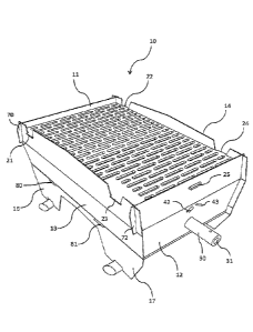
An embodiment of a grill device 10 according to the invention, which is
suitable in particular for outdoor activities, such as, for example, hiking
tours or camping, is shown in the figures. The grill device 10 shown in the
present exemplary embodiment includes a carrier frame and a cooking grill
20 which is attached to the carrier frame. The carrier frame is formed by
multiple plate-shaped walls, in particular by four side walls 11, 12, 13 and
14. A cuboid-shaped carrier frame with an upper opening is thus formed
overall, into which opening the cooking grill 20 is inserted. Two shorter side
walls 11 and 12, in this case, are connected together via two longer side
walls 13 and 14. Said form with two shorter and two longer side walls is not
12
CA 03075843 2020-03-13
to be understood, however, in a restricting manner but the description ap-
plies also to forms with side walls of the same length or with other ratios
between sides.
.. The underside of the grill device 10 is closed off by a bottom part 15
which
is connected to all side walls 11, 12 and 13, 14. In this case, the bottom
part 15 is also realized in a plate-shaped manner, but comprises an angu-
lation so that a concave channel is produced which extends between the
two shorter side walls 11 and 12. The bottom part 15 thus forms a drip
io channel which is preferably realized in a closed manner.
In addition, the grill device 10 comprises a heating device 30 which is op-
erated with a flammable gas. The heating device 30, in said embodiment,
is realized as a fuel rod with a round cross section which comprises multiple
outlet openings for the outflow of flammable gas, one outlet opening of
which is provided as an example with the reference numeral 34. Said outlet
openings 34 are arranged spaced apart from one another in a row over the
length of the fuel rod 30, multiple rows of which being able to be provided.
The heating device 30, however, can also have another form. For example,
it can also be realized as a cuboid or a flat plate with multiple outlet open-
ings for the outflow of gas.
The heating device 30 extends between the two shorter side walls 11 and
12 and is held on said side walls in respective bearing elements. Said bear-
ing elements are formed by openings in the short side walls 11 and 12. One
opening in the side wall 11, in this case, is realized by a slot 50, whilst
one
opening in the opposite side wall 12 is realized by a circular recess 51. The
tube of the fuel rod 30 comprises at one end a flattening 32 with which it is
pushed into the slot 50. The flattening 32 is introduced, for example, by a
pinch-off seam or a welding, by way of which the tube of the fuel rod is
closed in a gas-tight manner at said end. The fuel rod 30 is pushed into the
circular recess 51 with its other end. The connection for a storage container
13
CA 03075843 2020-03-13
with flammable gas in liquid form is also situated at said end of the fuel rod
30 so that at said end there is a gas inlet opening 31 via which gas is able
to flow into the fuel rod 30 in order then to escape through the outlet open-
ings 34. The end with the flattening 32 is realized, in contrast, in a gas-
tight
manner.
The gas inlet opening 31, and consequently the connection for a storage
container with gas in liquid form, is situated in the mounted state on the
outside of the carrier frame formed by the side walls, i.e. on the outside of
the side wall 12. This can be seen, in particular, in the view in fig. 1. The
fuel rod 30 consequently projects with a certain length beyond the side wall
12.
The roof-shaped flame cover 40 is arranged above the heating device 30.
The flame cover is realized in a manner that is known for conventional grills.
In particular, it comprises multiple flame openings 41 which are arranged
spaced apart from one another in two lateral rows.
The two longer side walls 13 and 14 each comprise on their bottom edges
a central indentation, by means of which in each case two supporting feet
16, 17 and 18, 19 are formed. One further, smaller indentation is formed
additionally in the bottom edges of each of said supporting feet 16, 17, 18,
19. With said indentions the grill device can be set up as an option on trans-
versely placed branches, as shown by the broken line in fig. 1.
Said various individual parts of the grill device are connected together by
multiple releasable plug-in connections. The four side walls 11, 12, 13, 14
are connected together at their perpendicular edges via plug-in connections
which are produced by hook-shaped lugs and insertion slots. Said lugs are
also designated as hook lugs below as they protrude from the side walls like
hooks. For example, the side wall 11 comprises on each of its lateral edges
a hook lug 70 and 71, whilst the opposite side wall 12 comprises two hook
14
CA 03075843 2020-03-13
lugs 72 and 73 on its lateral edges. Said hook lugs are situated in the upper
region of the side walls 11, 12 so that they are insertable from above into
corresponding slots in the two other side walls 13 and 14. The side wall 13
comprises two such insertion slots 91, 92, whilst the opposite side wall 14
comprises two insertion slots 93, 94.
The bottom part 15 is connected by way of further plug-in connections to
the side walls 11, 13 and 14. In the embodiment shown, there is no plug-
in connection to the side wall 12 as said side wall 12 is preferably mounted
last and a further plug-in connection in said region would make insertion of
the hook lugs 7, 73 from above into the insertion slots 92, 94 more difficult.
The bottom part 15 comprises four lugs 80, 81, 82, and 83 which are in-
sertable into corresponding slots 60, 61, 62, 63 in the side walls 13 and 14.
In this case, said lugs 80, 81, 82, 83 are also formed in a hook-shaped
manner, the hooks projecting in the direction of the side wall 11. When the
lugs 80, 81, 82, 83 are inserted into the slots 60, 61, 62, 63, the bottom
part 15 is consequently pressed slightly in the direction of the side wall 11
in order to realize hook-locking. Two further lugs 84 and 85 protrude on a
side of the bottom part 15 facing the side wall 11. Said lugs are formed by
simple bulges without any holding function. They are consequently inserted
simply into corresponding slots 64 and 65 in the side wall 11 and are not
hook-locked in this case. The lugs 84 and 85 simply rest in the slots 64 and
65 so that said slots 64, 65 are also to be designated as support slots.
Further support slots 66, 67, 68 and 69 are provided in the side wall 11 and
the side wall 12 in order to hold the flame cover 40. To this end, the flame
cover 40 comprises at each of its ends two simple lugs 42, 43 and 44, 45
which are inserted without hook-locking into the support slots 66, 67, 68
and 69. As a result of the angled roof form of the flame cover 40, the lugs
42, 43, 44, 45 and consequently the support slots 66, 67, 68, 69 are ar-
ranged at an angle.
CA 03075843 2020-03-13
The cooking grill 20 is also connected to the four side walls 11, 12, 13, 14
via lugs and receiving means. To this end, the cooking grill 20 comprises
four support teeth 21, 22, 23, and 24 which protrude from the sides. Said
.. support teeth can be placed from above in correspondingly formed receiving
means on the side walls which are upwardly open. Said receiving means
26, 27, 28 29 are situated, for example, on the upper edges of the longer
side walls 13 and 14 and their cross section widens upward. In addition, a
further protruding plug-in tooth 25 is formed on the cooking grill 20 which
is inserted into a further support slot 90 on the side wall 12.
In the state shown in fig. 1, the grill device 10 is completely assembled and
can be utilized for grilling items to be grilled on the cooking grill 20. To
this
end, a storage container with flammable gas in liquid form is connected to
the fuel rod 30, which can also include the attachment of pressure regula-
tors, pressure valves, hoses, etc. The grill device 10 is sturdy, very torsion-
resistant and safe to handle. In particular, the fuel rod 30, in this case, is
secured against movement within the openings 50 and 51, as will be de-
scribed by way of fig. 7.
In order to transfer the grill device 10 from its diverse individual parts
into
the state in fig. 1, a given assembly diagram is preferably complied with.
In particular, first of all the two longer side walls 13 and 14 are connected
to the shorter side wall 11 via the described plug-in connections. The two
side walls 13, 14 are spread slightly apart in order to connect the base part
to the three side walls 11, 13, 14 via the plug-in connections also described.
In addition, the end of the fuel rod 30 with the gas inlet opening 31 is
pushed from inside through the opening 51 in the side wall 12. In said state,
the other end of the fuel rod 30 with the flattening 32 is pushed through
the slot 50 in the side wall 11. To this end, the fuel rod 30 is tilted
slightly
upward about the longitudinal axis of the slot 50 in order to be able to push
a highly angled fastening portion 33 on the flattening 32 through the slot
16
CA 03075843 2020-03-13
50. Said operation is shown by way of an arrow in fig. 7. As the fuel rod 30
is inserted with play into the round opening 51, the side wall 12 can be
tilted slightly outward in order to push the flame cover 40 with its lugs 42,
43, 44, 45 into the support slots 66, 67, 68, 69. The side wall 12 is pressed
in the direction of the opposite side wall 11 in order to be able to hold the
flame cover 40 between the two side walls 11, 12. In said state, the side
wall 12 can be lowered downward 12 in order to insert the hook lugs 72 and
73 from above into the insertion slots 92 and 94 of the two side walls 13,
14. The cooking grill 20 is then inserted and lowered at an angle with its
plug-in tooth 25 into the slot 90. In this case, the support teeth 21, 22, 23,
24 can be placed in the receiving means 26, 27, 28, 29. As can be seen in
particular from the side view in fig. 5, the support teeth 21, 22, 23 and 24
each hook-lock with a projection in the lower region of a side wall of the
respective receiving means 26, 27, 28, 29 when the cooking grill 20 is in-
serted with its plug-in tooth 25 in the direction of the slot 90. The cooking
grill 20 can thus no longer be lifted easily upward out of the receiving means
26, 27, 28, 29. To this end, the cooking grill 20 has rather first of all to
be
pulled out of the slot 90 with its plug-in tooth 25 in order to release the
hook-locking with the projection of a respective receiving means. In addi-
tion, an indentation, into which a support tooth 21, 22, 23 and 24 is lowered
under a projection during insertion (see, for example, right-hand receiving
means 27 in fig. 5), can be provided on the bottom of a receiving means
26, 27, 28, 29. The cooking grill 20 is thus secured against a horizontal
movement, and in the case of the corresponding weight of the cooking grill
20 is held by gravity in the indentation. Said protection is lifted when the
cooking grill 20 is lifted with a pulling and tilting movement out of the slot
90 and the receiving means 26, 27, 28, 29.
In said end state, the fuel rod 30 is secured between the two openings 50,
51 against a movement as at least one blocking element, preferably how-
ever two blocking elements, act on the slot 50 (see fig. 7). A first blocking
element is formed by the fastening portion 33 which protrudes at an angle
17
CA 03075843 2020-03-13
a from the longitudinal axis of the fuel rod 30. It protrudes upward here
and has in said direction a height H which is greater than the height h of
the slot 50. The fastening portion 33 rests on the outside of the side wall
11 and, as a result of positive locking closure, prevents a movement of the
fuel rod 30 in the direction of the opposite side wall 12, as the fastening
portion does not pass through the slot 50 in said position. The fuel rod 30
can consequently not be pulled unintentionally out of the grill device
through the opening 51. If, for example, a hose and/or the storage con-
tainer for the flammable gas is pulled unintentionally, this does not result
io in a dangerous situation where a fuel rod 30 with flames is pulled out. Ra-
ther, the fuel rod 30 is always protected and safely accommodated in the
interior of the grill device.
Pushing the fuel rod 30 too far through the grill device is certainly also
prevented by a further blocking element. To this end, a widened projection
35 is provided on the end-side flattening 32 of the fuel rod 30. Said projec-
tion 35 has a width B which is greater than the width b of the slot 50 in the
side wall 11. The projection 35 consequently strikes against the inside of
the side wall 11 when the fuel rod 30 is pressed in said direction. The flat-
tening 32 in the slot 50 additionally brings about a protection against rota-
tion.
The fuel rod 30 is secured in the grill device 10 by said blocking elements
33, 35. However, said protection can be released by simple pulling and/or
turning movements when the grill device is disassembled. The previously
described assembly steps are carried out in the reverse order, first of all
the
side wall 12 being pulled upward out of the insertion slots 92, 94, etc. The
releasing of the fuel rod 30 out of the slot 50 is effected as a result of
pulling/tilting the fuel rod 30 upward. All further plug-in connections can
then be released and the fuel rod also removed from the side wall 12. At
the end, the entire grill device is present in multiple flat individual parts
18
= CA 03075843 2020-03-13
which can be stacked one on top of another so that they are able to be
transported preferably in a bag or a rucksack.
As can be seen, for example, from fig. 3, an opening is situated in the region
of the slot 50. The heating device can be ignited with a flame or spark
source through said opening.
19
, h ,
CA 03075843 2020-03-13
List of references:
Grill device
11,12,13,14 Side wall
5 15 Bottom part
16,17,18,19 Supporting foot
Cooking grill
21,22,23,24 Support tooth
Plug-in tooth
10 26,27,28,29 Receiving means
Heating device, fuel rod
31 Gas inlet opening
32 Flattening
33 Fastening portion
15 34 Outlet opening
Projection
Flame cover
41 Flame opening
42,43,44,45 Lug
20 50,51 Bearing element, opening
60,61,62,63 Slot
64,65,66,67,68,69 Support slot
70,71,72,73 Hook lug
80,81,82,83,84,85 Lug
25 90 Grill fixing, slot
91,92,93,94 Insertion slot