Note: Descriptions are shown in the official language in which they were submitted.
CA 03075906 2020-03-13
1
WO 2019/054882
PCT/N02018/050229
OFFSHORE WELLHEAD PLATFORM
The present invention relates to an offshore wellhead platform for use in the
oil and
gas industry, and in particular to an offshore wellhead platform that receives
hydrocarbon
fluids from at least one well and carries out processing of the received
hydrocarbon fluids to
produce processed or part processed hydrocarbon fluids for storage and/or
transport to
another installation.
Offshore platforms used in the oil and gas industry should be arranged in a
manner
that satisfies the required function of the platform and also that ideally
allows for efficiency
both in terms of the operation of the platform as well as also efficient
manufacture and
assembly. An offshore platform must include equipment specific to the
platform's purpose,
for example equipment for handling and processing hydrocarbons, and it must
also include
means for accessing the platform, which in known platforms may include a heli-
deck and a
landing area for a vessel. The platform must be able to be operated and
maintained by
remotely controlled systems and/or by personnel on the platform. Conventional
platforms
hence typically also include control and monitoring systems such as sensors
and CCTV as
well as facilities for personnel, such as lighting, living areas and so on. As
well as holding all
of the equipment and ancillary features required for operation the platform
must also allow
for access for maintenance and be arranged to permit loading and unloading of
materials
such as consumables and new equipment. Such materials may be delivered by
helicopter
or by a service vessel, with the delivery method varying dependent on the
nature of the
materials and their weight. Thus, known platforms typically also include a
crane for lifting
heavy items to and from a service vessel as well as a laydown area for
receiving such items.
There may be a gangway such as a so-called Walk to Work (W2W) systems for
transfer
personnel and loading or unloading of smaller/lighter items.
The structure of the platform has two main parts. A supporting sub-structure
that
extends from below the surface of the sea to above the surface of the sea, and
a topside
structure on top of the supporting structure. A commonly used supporting
structure is a
jacket, which has several columns and a framework connecting these columns.
The sub-
structure can be a floating structure or it may have a foundation at the sea
bed. In the latter
case the columns are usually held by pilings that are driven into the sea bed.
The topside
structure generally consists of a number of decks that hold the equipment
required by the
platforms. The decks are linked by a supporting framework and by stairways.
Most offshore platforms include at least a spider deck, which is the lowermost
deck
and interconnects between the topside and the jacket; a cellar deck, which
usually includes
a laydown area and can be the location for heavier equipment like transformers
and
compressors; and a weather deck, which is the uppermost deck and holds the
crane as well
CA 03075906 2020-03-13
2
WO 2019/(15-1882
PCT/N02018/050229
as providing space for helicopter access. If the offshore platform is a
production platform
then there may also be a separate deck for the emergency shutdown valve (the
ESDV deck)
and a process deck for holding process equipment. In this document process
equipment is
defined as equipment for processing the hydrocarbon fluids to produce
processed or part
processed hydrocarbon fluids. This typically includes equipment directly
involved in the
separation, removal and/or transformation processes carried out on hydrocarbon
fluids
received from the well which are employed to obtain hydrocarbons suitable for
use, sale,
storage and/or transport. Other decks may also be present, with the number of
decks and
the size of the platform varying depending on the required function of the
platform.
Viewed from a first aspect, the present invention provides an unmanned
offshore
wellhead platform for use in the oil and gas industry, the platform
comprising: riser hang-off
equipment for connection to at least one riser for flow of hydrocarbon fluids
from at least one
well; and process equipment for processing the hydrocarbon fluids to produce
processed or
part processed hydrocarbon fluids for storage and/or transport to another
installation,
wherein all of the process equipment is on a single process deck of the
platform.
With this arrangement the platform is an unmanned platform and has essentially
one
main deck. Advantageously the platform may be a single-deck platform,
comprising the
single process deck and no further deck(s), aside from optionally a weather
protection deck
and/or a lower access level for maintenance as described below. All of the
process
equipment (i.e. equipment as defined above, such as equipment that is directly
involved in
the separation, removal and/or transformation processes carried out on
hydrocarbon fluids
received from the well that are employed to obtain hydrocarbons suitable for
use, sale,
storage and/or transport) on the platform is located on the single process
deck and thus may
all be placed in essentially the same plane. This is in clear contrast to many
known
arrangements where multiple decks are used as mentioned above. Reducing the
number of
decks simplifies the construction of the platform and saves on costs and
material usage.
Placing all of the process equipment on a single process deck further
simplifies the platform
arrangement and may allow for more straightforward automation of the operation
of the
platform. These simplifications have a synergy with the additional proposed
feature that the
platform is unmanned (i.e. that it generally operates with no personnel
present as discussed
further below) since having a simpler platform reduces the need for
maintenance operations
and having a single process deck for all the process equipment can facilitate
more
straightforward automation of maintenance. For example, to move materials such
as spare
parts or consumables around a single process deck then a single remotely
controlled
handling system may be provided to move items horizontally around the single
process deck
and this will only need to operate in a restricted vertical extent, since a
floor level for all of
the process equipment may generally be in a single plane.
CA 03075906 2020-03-13
3
WO 2019/(154882
PCT/N02018/050229
In example embodiments the single process deck is the main deck of the
platform
and there are no other decks for equipment relating to the processing or
handling of
hydrocarbon fluids. For example, there may be no other decks aside from one or
more
decks provided for the purpose of facilitating weather protection, materials
handling and/or
access to the single process deck.
The processing equipment may include equipment for processing or part
processing
the hydrocarbon fluids, such as equipment for water handling and separation
for re-injection,
hydrocarbon separation, and/or gas reinjection equipment such as via ESP. The
platform
may comprise ancillary equipment required for operation of the wellhead
platform, and some
or all of this ancillary equipment may be located on the single process deck
along with the
process equipment. For example, the platform may include an electrical cabinet
and/or a
hydraulic cabinet for holding an electrical and/or a hydraulic control system
for the wellhead
platform, and this cabinet is advantageously located on the single process
deck. Example
embodiments use an electrical system rather than a hydraulic system in order
to allow for
minimal maintenance and reduce the need for personnel to be present at the
unmanned
platform.
The single process deck may be arranged to allow personnel to access the
process
equipment for maintenance purposes. However, since the platform is an unmanned
platform
then it is not intended for personnel to be present for normal operation. To
allow for
.. maintenance operations the single process deck may have a walkway for
enabling
personnel to access the process equipment and optionally other equipment on
the single
process deck. This walkway may also form an evacuation route for personnel to
leave the
platform single process deck in the event of an emergency such as a fire. An
added
advantage of the single process deck is that evacuation time is reduced and
this allows for
further enhancements to the design of the platform, such as in relation to
fire protection as
discussed below.
The single process deck may be arranged with the riser hang-off equipment at
the
centre. This may also involve placing the riser hang-off equipment at the
centre of the
platform, for example at the centre of both the single process deck and at the
centre of a
.. jacket that supports the deck. In this way the clearance around the riser
hang-off equipment
is maximised, and fluid pathways such as risers extending to the platform from
a subsea
location can also be sited with maximum clearance from the structural of the
platform and/or
the jacket, such as columns that support the single process deck. The riser
hang-off
equipment may be arranged to couple to multiple risers and all of the riser
hang-offs may be
grouped together centrally in the single process deck. The riser hang-off
equipment may
comprise riser hang-offs as well as associated structures and connections,
such as a
manifold for the hydrocarbon fluids.
CA 03075906 2020-03-13
4
WO 2019/(154882
PCT/N02018/050229
Processing equipment may be located at a non-central location on the single
process
deck and may be at an outer part of the deck spaced apart from the centre of
the deck. This
can have advantages in relation to access to lift the processing equipment as
discussed
below. Other potentially heavy items such as the optional electrical or
hydraulic cabinet may
also be located at a non-central location on the single process deck and may
be at an outer
part of the deck spaced apart from the centre of the deck.
The single process deck may include one or more materials handling device(s)
for
movement of materials around the single process deck. The materials handling
device(s)
may be arranged for movement of equipment about the plane of the single
process deck.
For example, this may be a crane such as a gantry crane.
The platform may comprise a weather deck as mentioned above. The weather deck
may have the primary purpose of shielding the single process deck from the
weather.
Optionally, the weather deck may support a crane for lifting heavy items to
and from the
single process deck. For example, a slewing jib crane may be used. The weather
deck and
the single process deck may be arranged such that there is access to certain
equipment on
the single process deck from above, for example by using the crane on the
weather deck for
lifting said equipment off the single process deck. This might include heavier
equipment that
is advantageously located at an outer location of the single process deck and
spaced apart
from the centre, such as the process equipment as set out above. In one
example, the
weather deck does not fully cover the single process deck and instead the
single process
deck may extend horizontally outward below the weather deck at the locations
of said
equipment to be lifted. In this case a crane on the weather deck, or
potentially a crane on a
service vessel, can lift the equipment vertically from the single process deck
since the
weather deck will not obstruct the lifting operation.
There may be a first crane on the single process deck for moving equipment in
the
plane of the single process deck and a second crane on the weather deck for
lifting
equipment vertically from the single process deck. In that case the platform
may
advantageously include a laydown area on the single process deck that is
accessible to both
the first crane and the second crane.
The platform may include an access level beneath the single process deck
allowing
for access for maintenance. For example, the access level may permit access to
lower parts
of the riser hang-off equipment and or to utilities passing beneath the floor
of the deck for
maintenance and inspection. The access level can hold essential, non-process
equipment,
such as Emergency Shutdown Valves (ESVs) and also provide a riser pull-in
level for use
when the platform is first commissioned and risers are connected. It is noted
that platforms
of the type described herein may include various valve arrangements for flow
control and/or
safety equipment that handles the hydrocarbons but does not process them, i.e.
does not
CA 03075906 2020-03-13
WO 2019/054882
PCT/N02018/050229
perform any transformation on the hydrocarbons. These valves and other similar
safety
components are not process equipment as defined herein.
In some examples the platform includes a single process deck holding all of
the
process equipment on the platform, a weather deck located above the single
process deck
5 and an access deck located below the single process deck. This platform
may include no
further decks or floor levels.
The proposed unmanned wellhead platform with a single process deck has a
restricted size and extent compared to multi-deck platforms and this means
that the
evacuation of personnel from the platform can be achieved within a relatively
short time.
This is another advantage of a single process deck arrangement. It will be
appreciated that
in this instance the personnel on the platform are temporarily present, for
example for
maintenance operations that cannot be performed remotely, since the platform
is an
unmanned platform. In general the platform would only be operated with
personnel on board
when a vessel such as a service vessel was also present and thus in this case
the
evacuation time required is the time needed for personnel to exit the platform
and board the
vessel, as well as for the vessel to be piloted to a safe distance. In
alternative arrangements
the platform may be used in a development including multiple platforms
connected via
bridges and therefore the evacuation time may include personnel exiting the
platform via a
bridge. Since there is only a single process deck then the maximum evacuation
time will not
need to include any significant allowance for traversing stairways or crossing
multiple decks.
Instead it may simply require any personnel on board to exit the single
process deck (or the
access level, where present) to a stairway or ladder that allows them to board
the vessel (or
cross a bridge). The evacuation time can therefore be very short.
The ability to reduce the evacuation time allows for other advantages to be
obtained
and for other simplifications to be made to the platform. For example, it can
be possible to
evacuate the platform quickly enough to avoid escalation even when there is no
emergency
depressurisation mechanism, such as a hot flare, and therefore the platform
may have no
emergency depressurisation mechanism. Alternatively, or in addition, in can be
possible to
evacuate the platform sufficiently quickly to avoid the need for any active
fire protection
(AFP) systems such that the platform may have only passive fire protection
(PEP) systems.
Moreover, the amount of passive fire protection that is required can be
minimised. The fire
protection of the platform may be designed such that the platform includes
only passive fire
protection and such that the passive fire protection is included only to the
extent required to
allow for evacuation, with the fire then being allow to escalate after the
required evacuation
time has passed.
It goes counter to established practice to allow for a fire to escalate and
potentially
destroy valuable equipment and thus it is not obvious to omit emergency
depressurisation
CA 03075906 2020-03-13
6
WO 2019/054882
PCT/N02018/050229
and to provide only a minimum of passive fire protection. The inventors have
realised that
the potential cost of permitted escalation of a fire (when evacuation is
completed) is
outweighed by the benefits to simplification of the platform since this allows
for reduced cost
and complexity when manufacturing and assembling the platform as well as
reduced cost of
operating the platform. In particular, an emergency depressurisation mechanism
and active
fire protection may require regular maintenance and inspection, which requires
personnel to
be present, so a platform without such features requires lesser maintenance
and fewer visits
from personnel. Passive fire protection may also require inspection and/or
maintenance and
so further advantages are realised when this is reduced. Allowing for
minimised
maintenance means the platform can operate for longer periods without
personnel present
and this contributes to the gains in efficiency and reductions in costs that
arise through using
an unmanned platform.
The platform may be arranged to have evacuation time that is at most 15
minutes.
This puts some limitations on the size of the platform and on the
accessibility and length of
the evacuation route(s). The platform may be arranged to have a maximum
evacuation time
of 10 minutes or below, optionally about 7 minutes or below. In example
embodiments the
evacuation time may be as low as 4 minutes or below. Reducing the maximum
evacuation
time by restricting the size of the platform can be done by reducing the size
of the single
process deck, arranging the deck for direct access to exit toward the escape
route to the
vessel (or bridge) and so on. Those skilled in the art will appreciate that
the variables relating
to the maximum evacuation time can be controlled during design of the
structure and layout
of the platform, especially when there is a focus on minimising the amount of
equipment that
is present.
Having a restriction on evacuation time sets a limit on the size of the
platform when
one considers the possible speed of movement of personnel during evacuation.
The
platform dimensions and layout, and in particular the dimension and layout of
the single
process deck, may be determined with reference to such considerations. The
deck may
have a maximum length and/or width of less than 30 m, optionally less than 25
m and in
some examples less than 20 m. For example the deck may be a square or
rectangle with
both length and width of less than 25 m or optionally less than 20 mi.
The platform is an unmanned platform and hence it is a platform that has no
permanent personnel and may only be occupied for particular operations such as
maintenance and/or installation of equipment. The unmanned platform may be a
platform
where no personnel are required to be present for the platform to carry out
its normal
function, for example day-to-day functions relating to handling of oil and/or
gas products at
the platform. There are added advantages to making an unmanned platform as
compact as
CA 03075906 2020-03-13
7
WO 2019/054882
PCT/N02018/050229
possible, and thus there is a synergy between the proposed single process deck
and the fact
that it is an unmanned platform.
An unmanned platform may be a platform with no provision of facilities for
personnel
to stay on the platform, for example there may be no shelters for personnel,
no toilet
facilities, no drinking water and/or no personnel operated communications
equipment. The
unmanned platform may also include no heli-deck and/or no lifeboat, and
advantageously
may be accessed in normal use solely by a gangway to a vessel or a bridge to
another
platform, for example via a Walk to Work (W2W) system as discussed below.
An unmanned platform may alternatively or additionally be defined based on the
relative amount of time that personnel are needed to be present on the
platform during
operation. This relative amount of time may be defined as maintenance hours
needed per
annum, for example, and an unmanned platform may be a platform requiring fewer
than
10,000 maintenance hours per year, optionally fewer than 5000 maintenance
hours per year,
perhaps fewer than 3000 maintenance hours per year. There is of course a clear
inter-
relationship between reducing the maintenance hours needed and the
minimisation of fire
protection, amongst other things. The current platform has been developed as a
part of a
general philosophy of minimising the amount of, and complexity of, the
equipment on the
unmanned platform, thereby allowing for the smallest and most cost effective
platform for a
given capability in terms of providing a function in the oil and gas
installation.
A further synergy arises due to the realisation by the inventors that an
unmanned
platform can be operated on the basis that whenever personnel are present on
the
unmanned platform then there should always be a way for direct access and
egress by the
personnel via a gangway or a bridge. This can lead to reductions in the
evacuation time and
thus aid in meeting the restrictions on the size of the platform.
In relation to the absence of emergency depressurisation mentioned above, the
platform may have no mechanism for emergency depressurisation of a hydrocarbon
inventory in the event of a fire, and the platform may be arranged to permit a
fire to escalate
by combustion of the hydrocarbon inventory after time is allowed for
evacuation of any
personnel that happen to be present.
The absence of depressurisation such as a flare can reduce the size and
complexity
of the platform, and whilst the lack of depressurisation generates an added
risk in the event
of escalation of a fire it has been unexpectedly found that the capability for
reduced size and
consequently reduced evacuation time means that the risk to personnel can be
avoided.
Thus, counter-intuitively, the absence of depressurisation does not result in
an increase in
risk, provided it is accompanied by a suitable restriction on the platform
size, which can
easily be achieved with the proposed single process deck. The restriction on
the size is
aided by the absence of a mechanism for emergency depressurisation, which
typically
CA 03075906 2020-03-13
8
WO 2019/054882
PCT/N02018/050229
requires a large amount of space and thus increases the possible maximum
evacuation
time. In addition, contrary to conventional platforms, the hydrocarbon
inventory is allowed to
burn if the fire is large enough to escalate to the hydrocarbon inventory, for
example by
rupture of the pressurised piping, and equipment on the platform can be
treated as sacrificial
in that situation.
In some cases the platform may have no depressurisation mechanism of any type,
although it may sometimes be useful to allow for a cold vent system for use in
maintenance.
It will be appreciated by those skilled in this field that there can be a
capability for a slow
speed depressurisation for use in maintenance (for example over several
minutes or hours),
whilst also having no ability for emergency depressurisation, which should
occur at high
speed with emission of large amounts of hydrocarbons in a short space of time,
within
seconds for example. There may be no flare, in particular there may be no hot
flare and
optionally no cold flare. For example there may be no large bore cold vent. In
other
arrangements a cold flare may be present but there may be no hot flare. The
exact set-up
may depend on regulatory requirements and on the nature of the equipment on
the platform,
which determines the size of the hydrocarbon inventory and the risks in the
event of a fire.
The platform may be arranged so that the equipment and piping are left at an
operating pressure in the event of a fire. The piping on the platform may be
isolated from
wells that are located subsea or at a separate structure and/or from pipelines
having large
inventories of oil or gas. For example, isolation valves may be present at
appropriate
locations, with these isolation valves being arranged to isolate the
hydrocarbon inventory of
the platform in the event of a fire. Thus, the equipment and piping may not
brought down to
atmospheric pressure in the event of a fire, but instead an operating pressure
is left in the
system. The pressure may change as a result of operation of other equipment
such as the
isolation valves and/or a drain tank or similar.
In the event of a fire the time to escalation without emergency
depressurisation will
generally be decreased compared to a similar platform with depressurisation.
The operating
pressure is not released, which means that the pipe stress will remain high or
increase while
the material ultimate tensile strength will decrease as it heats in the fire.
Rupture will
therefore occur sooner and at a higher pressure, causing the fire to escalate
sooner than
would be the case for a depressurised system. However, with the proposed
arrangement
this is quicker time to rupture can be acceptable. Due to the short evacuation
time resulting
from the restricted size of the platform via the use of a single process deck,
then if
maintenance personnel happen to be present they can still evacuate to a safe
distance
when the escalation of the fire happens. For certain pipes and/or equipment
passive fire
protection may be required to extend the time before escalation and allow
evacuation, but as
explained below the amount of passive fire protection can be minimised.
CA 03075906 2020-03-13
9
WO 2019/054882
PCT/N02018/050229
The layout and size of the platform may be based on determining a maximum
permitted evacuation time based on an estimate of the expected time for
escalation of the
fire, and then using this time to determine what size of platform can be
permitted, which may
be in combination with the absence of emergency depressurisation and/or in
combination
with the absence of active fire protection. This can be done based on
identifying the longest
safe evacuation time based on the expected time to escalation of the fire, and
ensuring that
all evacuation routes can be used within that evacuation time. The layout
and/or size of the
platform may be arranged in order to reduce the evacuation time if required.
Passive fire
protection may be included in order to increase the maximum permitted
evacuation time, for
example by adding optimised fire protection as described below.
The evacuation time for a given route can be calculated based on assessing the
nature of each part of the evacuation route, allocating a time required for a
person to
traverse each part of the evacuation route, and summing the times. For
example, an
evacuation route may require personnel to cross one or more deck(s), ascend or
descend
one or more flights of stair(s), and cross a gangway or bridge. In the case of
evacuation via a
vessel then the evacuation route may include boarding a vessel, detaching the
vessel from
the platform and piloting the vessel away from the platform to a safe
distance. The time
required for a person to traverse each part of a route may be based on the
length/distance
for the route and on a set speed for different types of route. Preferably the
speed is based on
evacuation of an injured person. Optionally the speed may be based on
favourable weather
conditions. In the case of an unmanned platform (as discussed below) personnel
would not
board the platform during adverse weather and therefore it may not be
necessary for the
speed during evacuation to take account of adverse weather. The speeds can be
based on
past experience and/or empirical calculations for speed of movement of a
person.
The evacuation time may take into account the time required for all personnel
on the
platform to exit the platform. Multiple personnel may wish to use the same
evacuation route,
or the same part of a route, at the same time. For example, there may be a
queue to board
a vessel. The determination of the maximum evacuation time may be done on
basis of a
maximum number of people on the platform and may include taking account of the
time
required for this number of people to all complete certain stages of the
evacuation route, for
example using a ladder, boarding a vessel and so on. The method may include
the platform
having a maximum limit on the number of personnel present. For example the
platform may
always have no more than 20 people present at any one time, optionally no more
than 15
people, and in some cases no more than 10 people. There may be a maximum limit
on the
number of people permitted to be present in order to thereby control the
evacuation time.
In addition to the time required to move from a location on the platform to
escape the
platform and/or get to a safe distance from the platform via an evacuation
route the method
CA 03075906 2020-03-13
WO 2019/05-1882
PCT/N02018/050229
may also include adding a time allowance for personnel to evaluate and
understand the
situation before a decision to escape the platform is made. As the platform is
very limited in
size and therefore complex thought should not be required to determine the
best evacuation
route then this time may be set at just a few seconds, for example as 15
seconds or less, or
5 as 10 seconds or less. A further time allowance may be added for
personnel to evaluate and
address injuries to other personnel before evacuating along with the injured
personnel. The
maximum evacuation time may include these types of thinking time as well as
the time
needed to pass along the evacuation route.
The assessment of evacuation time may include using a speed for a person
crossing
10 a deck, for example a speed in the range of 0.3 to 0.7 m/s for an
injured person being
evacuated across a flat deck, optionally a speed in the range 0.4 to 0.6 m/s,
for example a
speed of 0.5 m/s. The same speed may be used for an injured person crossing a
flat
gangway or bridge. An adjusted speed may be used in the event that the
evacuation route
includes an inclined walkway such as an inclined gangway. The assessment of
evacuation
time may include using a speed for an injured person evacuating via ascending
or
descending stairs, for example a speed in the range of 0.1 to 0.3 m/s for
stairs of standard
size, for example a speed of 0.2 m/s. The assessment of evacuation time may
include using
a speed for an injured person evacuating via ascending or descending ladders,
for example
a speed in the range of 0.05 to 0.2 m/s, such as a speed of 0.1 m/s. Stairs of
standard size
may be defined as stairs with a maximum pitch of stairs not to exceed 38 and
step height in
the range of 12-22 cm. The assessment of evacuation time may allow a set time
for
particular actions during the evacuation, such as opening a barrier, boarding
a vessel,
detaching the vessel from the platform and so on, and these times may be
determined
based on past experience and/or testing. Where a vessel is involved then the
assessment of
evacuation time may include using a speed and/or a set time for piloting the
vessel to a safe
distance. Since the platform is unmanned then this speed and/or time could be
determined
based on favourable (or non-severe) weather conditions on basis that the
platform is only
accessed by personnel in favourable weather, or at least not in severe
conditions.
The platform may include optimised passive fire protection that is provided to
equipment and/or piping on the platform in order to prevent escalation of the
fire that would
create a risk to personnel on the evacuation route(s) during the determined
evacuation time,
but that may permit escalation of the fire after the evacuation time has
passed.
This allows for the amount of fire protection to be optimised such that it can
be
implemented at a minimum level based on the determined maximum evacuation
time. A
small and compact single-deck platform can hence be developed with a minimal
amount of
fire protection. Of course, a safe platform could be easily provided with
extra fire protection
compared to the proposed optimised fire protection, but the inventors have
realised that
CA 03075906 2020-03-13
11
WO 2019/054882
PCT/N02018/050229
significant gains in efficiency are possible by the use of the proposed
optimisation.
Advantageously, the passive fire protection may be provided only to the extent
required to
prevent escalation of the fire that would create a risk to personnel on the
evacuation route(s)
during the determined evacuation time. Thus, there may be no further passive
fire protection
on the platform. Preferably there is no active fire protection at all. By
minimising the amount
of fire protection then the maintenance required for the fire protection can
be minimised, and
the space needed on the platform can also be kept to a minimum. As well as
this, the
installation costs are reduced. The inventors have taken the non-obvious step
of providing
fire protection that is optimised based on evacuation and would effectively
allow for the
equipment on the platform to be sacrificed in the rare event of a fire, since
provided the
platform is kept safe for evacuation then further escalation may not be
restricted by the fire
protection.
An unmanned platform can easily satisfy the requirement for a gangway or a
bridge
for use in evacuation since such a platform may either be interconnected with
another
platform, with personnel escaping via a bridge for example, or it may only
have personnel
present when the vessel that provided transport for the personnel is also
present and
provides a part of the evacuation route(s). Thus, the method may involve
evacuation route(s)
making use of a so-called "Walk to Work (W2W)" system for example using a
gangway from
a service vessel.
In the case where the method involves the use of a bridge to another platform,
then
the other platform may typically be associated with the same oil and gas
installation and it
may be the same type of platform or a different type of platform. For example,
the unmanned
wellhead platform to be evacuated may be connected by a bridge to another
wellhead
platform or to a production platform.
The length of the bridge may be set in order to provide a safe distance for
evacuation, although it is envisaged that other factors will require a bridge
to be of sufficient
length, and probably longer than required. For example, the distance between
platforms may
need to be above a certain minimum based on allowing safe navigation of
vessels. The
length of the bridge may be about 50 m or above, optionally about 75m or
above.
The evacuation route(s) may include different routes from different locations
on the
platform to an escape point via the gangway or bridge. The platform may have
just one
gangway or bridge that is hence common to all evacuation route(s). In the case
of a vessel
connecting to the platform via a gangway then the evacuation route may include
personnel
boarding the vessel and moving away from the platform to a safe distance by
using the
vessel. In the case of a bridge, for example to another platform, then the
evacuation route
may include traversing some or all of the bridge to get to a safe distance. In
determining the
evacuation route(s) the method may include considering all possible locations
for personnel
CA 03075906 2020-03-13
12
WO 2019/054882
PCT/N02018/050229
on the platform, and the route(s) that these personnel may use to escape via
the gangway or
bridge. Identifying the evacuation routes can include taking account of the
routes required for
traversing decks, climbing and/or descending stairs, climbing and/or
descending ladders,
descending escape chutes and/or moving around obstructions. Obstructions might
include
equipment permanently on the platform with a location or a possible location
that could block
some routes, for example a crane that might obstruct a preferred evacuation
route in some
positions. Obstructions might also include temporary objects, such as objects
being loaded
onto or removed from the platform during installation or maintenance.
Identifying the
evacuation routes may also include taking account of routes that may not be
available in the
case of evacuation of injured personnel. The method may include identifying
multiple
possible evacuation routes for the different locations for personnel on the
platform.
A maximum evacuation time can be determined based on the steps discussed above
and this may then be used in assessing the risk and determining the required
passive fire
protection for optimized passive fire protection. Assessing the risk to
personnel using the
evacuation route(s) in accordance with the determined maximum evacuation time
in the
event of a fire can include determining the likelihood of escalation that
would affect the
evacuation route(s) within the evacuation time. This may include taking
account of the
expected progression of evacuation of personnel along the evacuation route(s).
For
example, an increase in the level of danger at start of the evacuation route
may be permitted
once sufficient time has elapsed for personnel to have moved away from the
immediate
area. The platform may include passive fire protection that is provided for
equipment and/or
piping on the platform in order to prevent escalation of the fire that would
create a risk to
personnel on the evacuation route(s) during the determined evacuation time.
This may
include passive fire protection provided to the extent required to remove the
risk to personnel
on the evacuation route(s) during evacuation, and optionally the passive fire
protection may
only be provided to such an extent. By way of example, if there is a risk of
escalation within
the maximum evacuation time due to rupture of certain pipework in the vicinity
of an escape
route, or liable to affect an escape route then passive fire protection may be
provided to
restrict the increase in temperature of the pipework during a fire and/or to
increase the
strength of the pipework to make it more resistant to rupturing. Alternatively
or additionally, if
there is a risk of escalation within the maximum evacuation time due to
hydrocarbons
present in certain equipment in the vicinity of an escape route, or liable to
affect an escape
route then passive fire protection may be provided to restrict the increase in
temperature of
the equipment during a fire and/or to protect the equipment from to make it
more resistant to
ignition of the hydrocarbons and/or explosion of the equipment. Such equipment
may include
compressors, scrubbers, coolers, metering devices, valves and so on.
CA 03075906 2020-03-13
13
WO 2019/054882
PCT/N02018/050229
Another factor in prior art fire protection is avoidance of risk to the
structural stability
of the platform. This can provide benefits for the proposed platform as well,
although it will
be appreciated that the decision could alternatively be taken to sacrifice the
platform entirely
in some cases, for absolute minimum fire protection despite a risk to the
platform structure.
In the case of a relatively compact platform even with the optional absence of
depressurisation it is typically found that with appropriate isolation and
hence containment of
the hydrocarbon inventory, then the hydrocarbon inventory may be made small
enough to
permit it to burn out before any risk to the structural stability of the
platform, whilst avoiding
the need to add any further fire protection. Thus, in some examples, by
including isolation of
the hydrocarbon inventory then the platform can include optimised fire
protection both for the
protection of evacuating personnel and for the protection of the platform
structure.
Certain embodiments of the present invention will now be described in greater
detail
by way of example only and with reference to the accompanying drawings in
which:
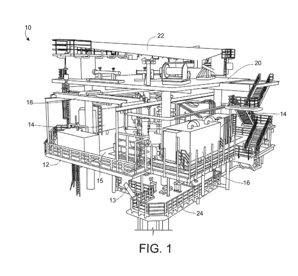
Figures 1 is a view of a 3D model of an example unmanned wellhead platform
with a
single deck for process equipment; and
Figure 2 shows the process equipment deck of the example platform with the
weather deck omitted so that the layout of single process deck can be seen.
The proposed unmanned wellhead platform can be used in a field development
comprising one or more wellhead platforms along with associated processing
platforms,
which may advantageously also be unmanned in the same way as the wellhead
platform. In
some examples the proposed unmanned wellhead platform is implemented as a part
of an
unmanned field development similar to that described in GB 1615681.2, GB
1615683.8, GB
1615686.1 or GB 1615687.9 and the unmanned wellhead platform described herein
may
replace one or more of the wellhead platforms described in those applications.
The platform is shown in in Figures 1 and 2 with an example layout. The
example
offshore wellhead platform 10 is an unmanned platform and hence personnel are
not
permanently present. The platform 10 also omits features that would be
required for
permanent personnel, such as a heli-deck, accommodation and toilet facilities
and so on. A
single process deck 12 is the main deck of the platform 10. This single
process deck 12
holds riser hang-off equipment 13 at a central part of the deck 12 and it also
holds all of the
process equipment 14 for the platform 12. Thus, there is no process equipment
14 on the
platform 10 aside from the process equipment 14 on the single process deck 12.
The
process equipment 14 may include water removal equipment, separators and so
on. In most
cases the process equipment 14 will only carry out partial processing of
hydrocarbons
received at the platform 10 via risers attached to the riser hang-off
equipment 13, for
example processing to remove water for reinjection and/or other processing to
allow for
more efficient transport of hydrocarbons to other installations for further
processing. The
CA 03075906 2020-03-13
14
WO 2019/(154882
PCT/N02018/050229
riser hang-off equipment 13 may include connections to multiple risers as well
as associated
manifolds and the like.
In addition to the process equipment 14 the single process deck 12 also holds
ancillary equipment needed for operation of the unmanned wellhead platform 10,
such as an
electrical cabinet 16 that holds an electrical control system and other
electrical sub-systems
for the unmanned wellhead platform 10. The single process deck 12 further
includes a
walkway 15 for use by personnel when they are present, i.e. for access to the
equipment 14,
16 for maintenance or inspection and for use in evacuating the platform 10
when needed.
It will be appreciated that the layout of the equipment on the single process
deck 12
could be varied compared to that shown whilst still obtaining the advantages
of having all of
the process equipment on a single floor.
The platform 10 further includes a weather deck 20 above parts of the single
process
deck 12 and an access level 24 below the single process deck 12. The weather
deck 20
protects the single process deck 12 from weather and the access level 24
allows for
personnel access below the single process deck 12 for maintenance and the
like. The
access level 24 can hold ESVs and also provide a riser pull-in level for use
when the
platform is first commissioned and risers are connected.
Handling of materials such as component parts and the like is enabled via a
gantry
crane 18 for moving items around the plane of the single process deck 12 and a
jib crane 22
on the weather deck 20 for lifting items off the process deck 12. Local
handling for each
item may involve the use of permanently installed pad eyes and monorails
and/or temporary
equipment in addition to the two cranes. The single process deck 12 is
designed for internal
horizontal transport handling from laydown areas to and from the location
where the items
are needed. The weather deck 20 does not extend across the full extent of the
single
process deck 12 in order to allow for vertical access to heavier equipment
such as the
process equipment 14 and the electrical cabinet 16. Thus, the jib crane 22 can
have access
to vertically lift such equipment from the single process deck 12.
Since all the main equipment, including all of the process equipment 14, is on
the
single process deck 12 and hence is in a single plane then the proposed
platform 10 allows
for greater automation and the use of robotics to augment the materials
handling solutions
that are used. Thus, the platform 10 may be arranged for remote and/or
automated
operation of the gantry crane 18 and/or the jib crane 22, as well as
optionally including
further automated systems for materials handling and/or for monitoring or
maintaining the
platform equipment, amongst other things. There are advantages to be gained
from
minimising the need for active human intervention and allowing for maximised
unmanned
operation of the platform.
CA 03075906 2020-03-13
WO 2019/(154882
PCT/N02018/050229
The platform 10 will allow for various evacuation routes from differing
locations using
the walkway 15 about the single process deck 12 and the stairways/ladders
shown in the
Figures. The evacuation routes need to be established with the slowest
evacuations being
used as the basis for a maximum evacuation time, which can then be used in
determining
5 what fire protection should be included in some examples, i.e. to allow
for optimised
(minimised) fire protection. The platform 10 is provided with passive fire
protection (PEP) in
order to ensure that a fire will not escalate until after any personnel that
are on the platform
have been safely evacuated. The platform 10 has no hot flare and in this
example there is no
mechanism of any sort for emergency depressurisation. It should be noted that
the absence
10 of a flare can increase the risk of a dangerous escalation of a fire,
since there is no
depressurisation. However, the absence of the flare contributes to allowing
for the size of the
platform 10 to be reduced and the evacuation time to be minimised. Moreover
since the
platform 10 is an unmanned platform then personnel will only be present with a
connection
via a bridge (not shown in this example) or a gangway to a service vessel
being present as
15 well, which means that the evacuation process can be very quick. It is
estimated that
personnel can escape to the stair tower within 1 minute after the initial
incident, and a
conservative assumption is that personnel will be on the service vessel within
10 minutes.
The evacuation time and/or the length of the route is assessed for various
evacuation
routes, or at least for the longest routes, in order to identify the
evacuation route with the
longest evacuation time. The evacuation time is calculated based on assessing
the nature of
each part of the evacuation route, allocating a time required for a person to
traverse each
part of the evacuation route, and summing the times. The time required for a
person to
traverse each part of a route is based on the length/distance for the route
and on a set
speed for different types of route. Preferably the speed is based on
evacuation of an injured
person. Optionally the speed may be based on favourable weather conditions. In
the case of
an unmanned platform personnel would not board the platform during adverse
weather and
therefore it may not be necessary for the speed during evacuation to take
account of
adverse weather. The speeds can be based on past experience and/or empirical
calculations for speed of movement of a person.
By way of example, the speed of movement may be set as follows:
Evacuation of uninjured person: 1.0 m/s for corridors (flat decks), 0.6 m/s
for stairs
and 0.3 m/s for ladders.
Evacuation of injured person: 0.5 m/s for corridors, 0.2 m/s for stairs and
0.3 m/s for
ladders.
The example platform above is about 20 m by 20 m. The longest evacuation route
is
determined to be from the far corner of the access level 24 or the far corner
of the single
process deck 12 to the stairway for access to a service vessel.
Conservatively, the distance
CA 03075906 2020-03-13
WO 2019/054 16882
PCT/N02018/050229
around the outer periphery across the deck is used. The escape route is hence
as follows:
walk around deck (about 40 m) and then walk via stairs to service vessel
(about 30 m,
partially stepped).
Using the speeds set out above, the evacuation time for non-injured and
injured
personnel can then be found. For a non-injured person the timings are: walk
around deck -
40 s, walk via stairs to service vessel - 50 s (using the slower stair speed
for the whole
distance to get a conservative time), with a total time of 90 s. For
evacuating an injured
person the timings are: walk diagonal across deck - 80 s, walk via stairs to
service vessel -
150 s, with a total time of 230 s.
The evacuation time is used in assessing the risk and determining the required
passive fire protection. Passive fire protection is provided to equipment
and/or piping on the
platform in order to prevent escalation of the fire that would create a risk
to personnel on the
evacuation route(s) during the determined evacuation time. For minimum fire
protection this
includes providing passive fire protection only to the extent required to
remove the risk to
personnel on the evacuation route(s) during evacuation. Thus, if there is a
risk of escalation
within the maximum evacuation time due to rupture of certain pipework in the
vicinity of an
escape route, or liable to affect an escape route then passive fire protection
is provided to
restrict the increase in temperature of the pipework during a fire and/or to
increase the
strength of the pipework to make it more resistant to rupturing. Alternatively
or additionally, if
there is a risk of escalation within the maximum evacuation time due to
hydrocarbons
present in certain equipment in the vicinity of an escape route, or liable to
affect an escape
route then passive fire protection is provided to restrict the increase in
temperature of the
equipment during a fire and/or to protect the equipment from to make it more
resistant to
ignition of the hydrocarbons and/or explosion of the equipment. Such equipment
may include
compressors, scrubbers, coolers, metering devices, valves and so on.