Note: Descriptions are shown in the official language in which they were submitted.
OVERPRESSURE MITIGATION SYSTEMS FOR HYDRAULIC FRACTURING
TECHNICAL FIELD
[0001] The present description relates in general to hydraulic fracturing
operations, and
more particularly, for example and without limitation, to systems and methods
for mitigating
fluid hammer effects during pumping of fracturing fluids.
BACKGROUND OF THE DISCLOSURE
[0002] In the production of oil and gas in the field, it is often required
to pump a fluid
down a wellbore in a subterranean formation. In one example, fracturing fluid
is pumped
from the surface into the wellbore during hydraulic fracturing operations to
generate, extend,
and/or prop open one or more fractures in the formation.
[0003] However, challenges can arise when pumping a fluid into a wellbore,
particularly
when the wellbore extends long distances (e.g., miles) into the formation.
SUMMARY
[0003a] In one aspect, there is provided a method comprising: pumping a fluid
into a
wellbore in a subterranean formation; while pumping the fluid, obtaining
downhole pressure
measurements using a downhole pressure sensor; determining a rate of change of
a downhole
pressure in the fluid based on the downhole pressure measurements; comparing
the rate of
change of the downhole pressure with a threshold; and determining whether a
downhole flow
stoppage has occurred based on the comparison.
10003b] In another aspect, there is provided a well system comprising: at
least one pump
configured to provide a fluid into a wellbore in a subterranean formation; a
downhole
pressure sensor in the wellbore; and a controller communicatively coupled to
the downhole
pressure sensor and the at least one pump, wherein the controller comprises
overpressure
mitigation circuitry configured to: obtain downhole pressure measurements
using the
downhole pressure sensor while the at least one pump provides the fluid into
the wellbore;
determine a rate of change of a downhole pressure in the fluid based on the
downhole
pressure measurements; compare the rate of change of the downhole pressure
with a
1
Date Recue/Date Received 2021-08-16
threshold; and determine whether a downhole flow stoppage has occurred based
on the
comparison.
[0003c] In another aspect, there is provided a controller for a fracturing
fluid pump
configured to pump a fracturing fluid into a wellbore in a subterranean
formation, the
controller comprising overpressure mitigation circuitry configured to: obtain
downhole
pressure measurements using a downhole pressure sensor in the wellbore while
the fracturing
fluid pump provides the fluid into the wellbore; determine a rate of change of
a downhole
pressure in the fluid based on the downhole pressure measurements; compare the
rate of
change of the downhole pressure with a threshold that is based on a speed of
sound in the
fracturing fluid; and determine whether a downhole flow stoppage has occurred
based on the
comparison.
BRIEF DESCRIPTION OF THE DRAWINGS
[0004] The following figures are included to illustrate certain aspects of
the present
disclosure, and should not be viewed as exclusive embodiments. The subject
matter
disclosed is capable of considerable modifications, alterations, combinations,
and equivalents
in form and function, without departing from the scope of this disclosure.
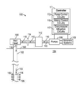
[0005] FIG. 1 is a diagram of a system having a wellbore and associated
pumping
equipment, according to some embodiments of the present disclosure.
[0006] FIG. 2 is a diagram of the system of FIG. 1 in the event of a
downhole flow
restriction, according to some embodiments of the present disclosure.
[0007] FIG. 3 is a diagram of the system of FIG. 2 illustrating a fluid
hammer effect
caused the downhole flow restriction, according to some embodiments of the
present
disclosure.
[0008] FIG. 4 is a flow diagram for overpressure mitigation for the system
of FIG. 1,
according to some embodiments of the present disclosure.
la
Date Recue/Date Received 2021-08-16
CA 03075993 2020-03-16
WO 2019/117862 PCMJS2017/065772
DETAILED DESCRIPTION
100091 The detailed description set forth below is intended as a
description of various
implementations and is not intended to represent the only implementations in
which the subject
technology may be practiced. As those skilled in the art would realize, the
described
implementations may be modified in various different ways, all without
departing from the scope
of the present disclosure. Accordingly, the drawings and description are to be
regarded as
illustrative in nature and not restrictive.
100101 The present disclosure is related to hydraulic fracturing of
subterranean hydrocarbon-
producing wells and, more particularly, systems and methods for mitigating
fluid hammer effects
during hydraulic fracturing operations for stimulating the production of
hydrocarbons.
100111 Subterranean hydraulic fracturing (alternately referred to as
"fracking") is sometimes
conducted to increase or stimulate production from hydrocarbon-producing
wells. In hydraulic
fracturing, a fracturing fluid is pumped at an elevated pressure from a
wellbore into adjacent
hydrocarbon-bearing subterranean formations. The pumped fracturing fluid
splits or "fractures"
the rock formation along veins or planes extending laterally from the
wellbore.
100121 In some applications, the fracturing fluid contains propping agents
(alternately
referred to as "proppant") that are also injected into the opened fractures.
Once a desired
fracture network is formed, the fluid flow is reversed and the liquid portion
of the fracturing fluid
is removed. The proppant is intentionally left behind to prevent the fractures
from closing onto
themselves due to the weight and stresses within the formation. Accordingly,
the proppant
"props" or supports the fractures to remain open, yet remain permeable to
hydrocarbon fluid
flow since they form a packed bed of particles with interstitial void space
connectivity.
100131 Hydraulic fractures near the wellbore wall are ideally simple,
straight, and wide to
provide a direct fluid pathway between the wellbore and the deeper parts of
the formation. Once
farther into the formation, then it is preferable to generate a complex
fracture network that
maximizes reservoir contact.
100141 In some circumstances, while pumping fluid into a wellbore, the
fluid flow can
become obstructed. For example, during hydraulic fracturing operations, a
"screenout" (also
known as a "sandout") can occur. Screenout is a condition that occurs when the
fracture network
at or near the wellbore wall becomes too complex or restricted and the
proppant substantially
2
CA 03075993 2020-03-16
WO 2019/117862 PCT/US2017/065772
plugs the fractures and thereby prevents the fracturing fluid from flowing
deeper into the
formation at that location.
[0015] When there is a downhole flow stoppage such as from a well
screenout, a fluid
hammer effect, described in further detail hereinafter, can occur in the fluid
in the wellbore
and/or surface fluid flow conduits. Fluid hammer effects of this type can be
damaging to the
wellbore, the wellhead, and/or fluid pumping or other surface equipment.
[0016] In accordance with various aspects of the subject disclosure,
systems and methods
are described that mitigate and/or prevent a damaging fluid hammer in the
fluid. For example, a
downhole pressure sensor can provide downhole pressure measurements to
overpressure
prevention equipment at the surface. The overpressure prevention equipment
includes
processing circuitry, sometimes referred to herein as overpressure mitigation
circuitry, that
processes the downhole pressure measurements and controls fluid pumps at the
surface
responsive to the downhole pressure measurements.
[0017] FIG. 1 is a schematic diagram of an example well system 100,
according to various
aspects of the subject disclosure. As illustrated, the well system 100
includes a wellhead 106
arranged at the Earth's surface 150 and a wellbore 102 that extends from the
wellhead 106 and
penetrates a subterranean earth formation 104. Even though FIG. 1 depicts a
land-based
wellhead, the embodiments of the present disclosure are equally well suited
for use by other
types of surface installations or rigs, such as offshore platforms, land-based
rigs, or rigs used in
any other geographical location.
[0018] In various scenarios, a work string (not shown) may be disposed in
wellbore 102. As
used herein, the term "work string" refers to one or more types of connected
lengths of tubulars
or pipe, such as drill pipe, drill string, landing string, production tubing,
coiled tubing,
combinations thereof, or the like. A work string may be used to stimulate
(i.e., hydraulically
fracture or "frack") portions of the wellbore 102 or the work string may be
entirely omitted and
wellbore 102 may nonetheless be stimulated using the systems and methods
described herein.
[0019] As illustrated, the wellbore 102 extends vertically away from the
surface 150. In
many well systems, a branch or lateral wellbore may also extend laterally from
the wellbore 102.
Alternatively, the wellbore 102 itself may deviate from vertical to form a
lateral wellbore across
a deviated or horizontal portion thereof. Although not explicitly shown, in
various scenarios,
3
CA 03075993 2020-03-16
WO 2019/117862 PCT/US2017/065772
wellbore 102 may be at least partially lined with a casing string or may
otherwise remain at least
partially uncased.
100201 During fluid pumping operations, in one example, a work string may
be coupled to a
completion assembly extended into and deployed in wellbore 102 using one or
more packers.
Packers may seal an annulus defined between the completion assembly and the
inner wall of
wellbore 102 and thereby effectively divide subterranean formation 104 into
multiple production
intervals or pay zones. Each interval may be independently or simultaneously
stimulated (e.g.,
hydraulically fractured or `Tracked") using the systems and methods described
herein.
100211 In the completion assembly example, a sliding sleeve assembly may be
arranged
within the work string at each interval, each sliding sleeve assembly axially
movable within the
work string to expose or occlude one or more ports defined therein. Once
exposed, the ports
may facilitate fluid communication into the annulus from the interior of the
work string such that
hydraulic fracturing operations may be undertaken in each corresponding
interval.
100221 In other embodiments, however, the completion assembly may be
omitted from the
well system 100 and wellbore 102 may instead be lined with casing and
perforated in strategic
locations to facilitate fluid communication between the interior of the casing
and each
corresponding interval. In such embodiments, wellbore 102 may nonetheless be
stimulated using
the systems and methods described herein by hydraulically fracturing the
formation 104 via the
perforations.
100231 To facilitate hydraulic fracturing of the formation 104, the system
100 may also
include a fracturing controller 111. Controller l 1 1 communicates with a work
string or a casing
string so that a prepared fracturing fluid 103 can be pumped to wellhead 106
via surface conduits
110, down wellbore 102, and out through one or more ports or perforations (as
indicated by
arrows 105) into selected intervals to fracture the formation 104 adjacent the
corresponding
intervals. As illustrated, fracturing controller 111 includes pump control
circuitry 113 for
operating one or more pumps 108 to pump fluid 103 into the wellbore.
Controller 111 also
includes mixing control circuitry 115 and overpressure mitigation circuitry
117.
100241 In some scenarios, as illustrated, the controller 111 may be
arranged at the surface
150 adjacent the wellhead 106. In other scenarios, however, controller 111 may
be remotely
located and able to communicate with the systems 109 and pumps 108 via wired
or wireless
telecommunications.
4
CA 03075993 2020-03-16
WO 2019/117862 PCT/US2017/065772
100251 Mixing control circuitry 115 controls the relative concentrations of
fluids and other
substances such as proppant that are combined from materials systems 109
(e.g., a fluid system
and a proppant system) to form fluid 103. For example, mixing control
circuitry 115 may
operate materials system 109 to mix and dispense fracturing fluid 103 having
desired fluid
properties (e.g., viscosity, density, fluid quality, etc.). Materials system
109 may include a
blender and sources of known substances that are combined in the blender to
produce fracturing
fluid 103.
100261 Materials systems 109 may also include proppant contained in one or
more proppant
storage devices, and a transfer apparatus that conveys the proppant from the
storage device(s) to
the fluid system for blending.
100271 Pumps 108 receive the prepared fracturing fluid from materials
system 109 and may
include a series of positive displacement pumps (referred to as fracturing or
"frac" pumps) that
inject fracturing fluid 103 into the wellbore 102 under specified pressures
and at predetermined
flow rates. Operation of pumps 108 is controlled by pump control circuitry 113
and/or
overpressure mitigation circuitry 117.
100281 Controller 111 includes hardware and software (e.g., a programmed
computer) that
allow a well operator to manually or autonomously control materials system 109
and pumps 108.
Data from the fracturing operation, including real-time data from one or more
sensors such as
surface pressure sensor 116 and/or downhole pressure sensor 118 in wellbore
102, from pumps
108, and/or from materials system 109 is received and processed by controller
111. In response
to this real-time data, controller 111 provides control (command) signals to
the materials system
109 and pumps 108.
100291 In some cases, well system 100 may include a relief valve 112 on the
surface between
pumps 108 and wellhead 106 to protect the wellhead and downhole equipment from
overpressure damage. In these examples, check valve 114 is provided between
surface relief
valve 112 and wellhead 106. If relief valve 112 opens, check valve 114
immediately seats and
traps a fluid-hammer wave between check valve 114 and wellbore 102. Because of
potential
well control issues, the relief valve should not be placed between the check
valve and wellhead.
However, even with overpressure safety equipment such as relief valve 112 and
check valve 114,
if a flow stoppage occurs down hole, the maximum pressure down hole will have
already
occurred before the pressure rise is observed at the surface (e.g., by a
release of relief valve 112
CA 03075993 2020-03-16
WO 2019/117862 PCT/US2017/065772
and/or in surface pressure measurements obtained at surface pressure sensor
116). As a result,
surface relief equipment such as relief valve 112 and check valve 114, may not
provide sufficient
protection against a peak fluid-hammer wave pressure down hole.
[0030] In order to mitigate or prevent a fluid hammer wave of this type,
overpressure
mitigation circuitry 117 receives downhole pressure measurements from downhole
pressure
sensor 118 and determines and monitors a rate of change of the downhole
pressure from the
received downhole pressure measurements. When the rate of change of the
downhole pressure
exceeds a rate threshold, overpressure mitigation circuitry 117 may determine
that a downhole
flow stoppage has occurred and may stop operation of pumps 108 to mitigate or
prevent a fluid
hammer effect from occurring within fluid 103.
[0031] The rate threshold is specific to the well system 100 and may depend
on a fluid flow
rate of fluid 103, the fluid volume, the proppant concentration in fluid 103,
and/or the speed of
sound in fluid 103.
[0032] FIG. 2 depicts a scenario in which there is a downhole flow stoppage
such as from a
well screenout, and the kinetic energy of the moving fluid in the well is
converted to potential
energy (pressure) of a static fluid. If care is not taken, this absorbed
kinetic energy becomes a
fluid-hammer pressure.
[0033] A liquid, although usually considered to be incompressible, is
actually slightly
compressible. Because a liquid is compressible and has mass, compression waves
can occur in
fluid 103 if care is not taken, and the fluid can be modeled as a mass and a
spring. The following
mass-and-spring analogy describes the phenomenon of fluid-hammer pressure in a
liquid.
[0034] The fluid flowing down the work string in FIG. 2 can be modeled as
multiple masses
and springs extending down the wellbore. If fluid is being pumped down the
work string and
then suddenly stops because of downhole flow stoppage as indicated in FIG. 2,
the upper mass
will push on the lower mass through the middle spring(s).
[0035] The push of the upper mass through the middle spring along with the
downward push
of the lower mass will compress the lower spring. This compression of the
spring is equivalent to
a rise in bottomhole pressure (BHP) in the well, which, in the systems and
methods disclosed
herein can be detected using sensor 118. In the scenario of FIG. 2, the
downward momentum of
the masses will continue to compress the middle and lower springs until they
absorb all of the
energy of the moving masses. After fully compressing the middle and lower
springs, the masses
6
CA 03075993 2020-03-16
WO 2019/117862 PCT/US2017/065772
will rebound, and their upward momentum, indicated by arrow 200 in FIG. 2,
will cause
compression of the upper springs and extension of the lower spring. This will
cause a rise of
surface tubing pressure and a drop in BHP. This movement of the springs and
masses can be said
to constitute the "fluid-hammer wave", indicated by arrows 300 of FIG. 3.
100361 If there were no frictional losses, the springs and masses indicated
by arrows 300 of
FIG. 3 would continue to oscillate indefinitely. However, in reality, the
fluid friction in the work
string and leakoff to the formation causes the fluid pressure oscillations of
the water-hammer
wave to decay.
100371 If the fluid flow into the well were to be stopped at the exact
instant that the flow
stoppage occurs downhole, then there would be a sudden drop of surface tubing
pressure after
the flow stoppage. However, in conventional systems (e.g., systems that do not
sense downhole
pressure and/or that do not generate (e.g., real-time) system-specific rate-of-
change thresholds as
described herein), during the time that the fluid-hammer pressure is rising
downhole, fluid
continues to be pumped into the well. The transit time for the fluid-hammer
pressure wave to
reach the surface depends on the well's depth, DW, as indicated in FIGS. 2 and
3, and the speed
of sound in fluid 103. Therefore, the deeper the well, the longer the transit
time, and
consequently, if fluid flow is not stopped, more fluid will be compressed into
the tubing before
the fluid-hammer pressure wave reaches the surface. This compressed fluid is
the cause of fluid
compression pressure. It should be appreciated that, although wellbore 102 is
depicted as a
purely vertical well with a depth DW, wellbore 102 may include a horizontal
portion, in which
case DW represents the overall length of the well and not only the depth of
the vertical portion.
100381 Immediately after the flow stoppage, the flow rate at the flow
stoppage point is zero.
If fluid flow is not stopped upon flow stoppage downhole, as fluid continues
to compress on the
bottom of the well, the point of zero flow rate rises toward the surface. This
reduces the average
flow rate and resulting friction pressure in the tubulars. This friction
pressure can be further
reduced by dropping the flow rate into the tubulars. If the surface flow rate
is suddenly cut
because of the rise in pressure observed at the surface, then there will be
some additional
reduction in surface pressure. If the reduction in friction pressure and
pressure reduction caused
by flow stoppage at the surface is occurring faster than the rise in fluid
compression pressure,
then the first reflected wave after the flow stoppage will not be as severe as
possible. As a result,
in the scenarios depicted in FIGS. 2 and 3, the second reflected wave can be
worse than the first.
7
CA 03075993 2020-03-16
WO 2019/117862 PCT/US2017/065772
For this reason, detection of a rise in pressure at the surface (e.g., using
only surface pressure
sensor 116) may not be sufficient (or sufficiently soon after a stoppage) to
mitigate damage to
downhole or other equipment.
100391 Accordingly, overpressure mitigation circuitry 117 stops pumping of
pumps 108
based on the BHP, and more particularly, based on an increase in the rate of
change of the BHP
beyond a threshold that is based on the specific properties of the well system
100. The system-
specific threshold may be based on a fluid flow rate of fluid 103, the fluid
volume, the proppant
concentration in fluid 103, and/or the speed of sound in fluid 103 as, for
example, described by
the derivations included hereinafter.
100401 To solve for the fluid-hammer pressure in a well system, the kinetic
energy equation
is set equal to the potential energy equation, and then the resulting equation
is rearranged to yield
the pressure. This is shown in the following equations:
.KE ---.1 pL4v2= .0)
1 .ufp'
ply; = (2)
Z
At a flow stoppage, the kinetic energy is the same as the potential energy,
and thus:
0):
f
where, KE = kinetic energy, PE= potential energy, p = absolute fluid density,
L = flow
length (see, e.g., DW above), A= flow area, v = fluid velocity, f = liquid
fraction of proppant-
laden gel, and P = fluid hammer pressure in fluid. The liquid fraction of a
proppant-laden gel
can be determined using Equation 4 below:
Dent o-iNgpc
. Pr opsv-1.
. I.+ P.r opsv.0 Av)
f :(4)
:Qoni,11*.Pt
8
CA 03075993 2020-03-16
WO 2019/117862 PCT/US2017/065772
where, Denb = density of a base gel, Avgpc = average proppant concentration,
Propsv =
proppant specific volume, and fle = effective bulk modulus of the pipe and the
fluid.
100411 From Equation (3) for water-hammer pressure above, it can be
observed that the
higher the velocity, density, and bulk modulus of the fluid, the higher the
pressure wave will be
when the fluid is suddenly stopped. A lower volume fraction of liquid also
increases this final
pressure. Because only the velocity is outside the square root, the velocity
will have the greatest
impact on the pressure.
100421 The basic equation used to calculate the fluid-compression pressure
is the equation
defining the bulk modulus,
AP441*f
(5)
AV
where /3 = bulk modulus, AP = compressional pressure, V = volume of fluid, and
AV =
change in volume (how much additional fluid is pumped into a closed system).
100431 Rearranging this equation allows for the calculation of the
compressional pressure
and provides Equation 6 which shows the change in pressure:
LIV
AP (6)
* f
100441 An effective bulk modulus can be calculated from the bulk modulus of
the fluid and
the bulk modulus of the tubing or casing. The following equations (7) and (8)
are used to
combine these:
Pe 1 (7)
PP flf
TE
.flp
where flp = bulk modulus of tubing or casing, T = wall thickness, E = steel
modulus of
elasticity (e.g., = 30,000,000 psi), D = ID of tubing or casing, flf =bulk
modulus of fluid (e.g., =
300,000 to 400,000 psi).
9
CA 03075993 2020-03-16
WO 2019/117862 PCT/US2017/065772
100451 Graphical techniques and a fluid-hammer calculator based on the
equations above,
can be both used to predict the surface pressure peaks resulting from a fluid
hammer caused by a
flow stoppage. According to these predictions, the first surface pressure peak
should be the
largest peak, the following peaks decaying in magnitude due to leakoff into
the formation.
However, it has been discovered that, perhaps due to a sudden drop in friction
pressure in the
fluid and/or a non-instantaneous flow stoppage, the first peak is often not
the largest peak.
100461 Because of the length of the well, several seconds of pumping can
therefore continue
after a downhole flow stoppage before a surface pressure sensor such as sensor
116 of FIG. 1 can
detect the flow stoppage. This continued pumping can keep the flow rate high
which, as noted
above in connection with Eq. (3) can result in a higher fluid-hammer pressure
than would have
occurred if the pumping had been stopped at the time of the flow stoppage.
100471 Accordingly, the downhole pressure measurements provided by downhole
pressure
sensor 118 can be helpful in identifying the flow stoppage closer to the time
at which the flow
stoppage occurs. However, it can be difficult to identify a flow stoppage from
pressure changes
alone as the downhole pressure fluctuates even in the absence of a flow
stoppage.
100481 Advantageously, it has also been discovered that, based on the fluid-
hammer
equations above and corroborated by field data, a signature of a flow stoppage
for each particular
well system can be identified in the rate of change of the downhole pressure.
Accordingly, a rate
of change threshold for the downhole pressure can be identified for each well
system at any
given time. In particular, overpressure mitigation circuitry 117 uses downhole
pressure sensor
118 to monitor the rate of change of the downhole pressure and compare the
monitored rate of
change with the determined threshold for that well system at that time.
100491 For example, as soon as a rate of change of downhole pressure that
is monitored by
overpressure mitigation circuitry 117 approaches the rate-of-change threshold
of a fluid hammer
compressional pressure rise (e.g., a rate-of-change of pressure threshold as
defined by AP in Eq.
6 above based on the fluid flowrate (v), fluid volume (V), proppant
concentration (Avgpc), and/or
speed of sound in the fluid), overpressure mitigation circuitry 117
immediately shuts down the
surface pumps (e.g., pumps 108). Since the compressional pressure would not be
offsetting the
friction pressure, the peak surface pressure would be reduced by the
difference between the
friction pressure and any compressional pressure occurring before the pumps
can be shut down.
CA 03075993 2020-03-16
WO 2019/117862 PCT/US2017/065772
This will reduce both the downhole and surface peak pressures by stopping the
pumps from
continuing to pump at the surface after the flow stoppage has already occurred
downhole.
[0050] The speed of sound in the fluid can be determined while pumping by
transforming
(e.g., using a Fourier transform such as a fast Fourier transform (FFT)
operation) on the surface
or downhole pressure measurements and determining the time to reflect from
surface to a
downhole reflector at a known depth such as the rathole (if no tools are in
the hole) or to a tool or
sand plug in the hole.
[0051] FIG. 4 depicts a flow diagram of an example process for overpressure
mitigation in a
well system such as well system 100 of FIG. 1, according to aspects of the
subject technology.
For explanatory purposes, the example process of FIG. 4 is described herein
with reference to the
components of FIGS. 1-3. Further for explanatory purposes, the blocks of the
example process
of FIG. 4 are described herein as occurring in series, or linearly. However,
multiple blocks of
the example process of FIG. 4 may occur in parallel. In addition, the blocks
of the example
process of FIG. 4 need not be performed in the order shown and/or one or more
of the blocks of
the example process of FIG. 4 need not be performed.
[0052] In the depicted example flow diagram, at block 400, fluid such as
fracking fluid is
provided (e.g., pumped, using pumps 108) into a wellbore such as wellbore 102
in a subterranean
formation such as formation 104.
[0053] At block 402, while providing the fluid, one or more downhole
pressure
measurements representing the downhole pressure in the fluid are obtained
(e.g., using pressure
sensor 118).
[0054] At block 404, a change in the downhole pressure is identified (e.g.,
by overpressure
mitigation circuitry 117) based on the downhole pressure measurement(s).
[0055] At block 406, a rate of the change is identified (e.g., by
overpressure mitigation
circuitry 117).
[0056] At block 408, a rate threshold associated with the fluid, the
wellbore, the subterranean
formation, a casing, and/or other features of the well system is determined
(e.g., by overpressure
mitigation circuitry 117). As described herein, the threshold is based on a
flow rate of the fluid,
the fluid volume, the proppant concentration in the fluid, and/or the speed of
sound in the fluid.
Determining the rate threshold may include determining the speed of sound in
the fluid. Because
each well system, including the fluid at any given time during fluid pumping,
is unique,
11
CA 03075993 2020-03-16
WO 2019/117862 PCT/US2017/065772
determining the speed of sound may include experimentally determining the
speed of sound in
the fluid during pumping. For example, samples of pressure measurements from a
surface
pressure sensor and/or a downhole pressure sensors may be frequency
transformed (e.g., using a
Fourier transform such as a fast Fourier transform). The frequency transformed
measurements
will have features corresponding to pressure wave reflections from downhole
objects such as the
rathole, if no tools are in the hole, or to a tool or sand plug in the hole.
Using known distances to
one or more of the downhole objects and using the frequency features in the
transformed data
that correspond to those downhole features, the speed of sound is determined.
100571 At block 410, the system (e.g., overpressure mitigation circuitry
117) determines
whether the identified rate of change violates (e.g., exceeds) the determined
threshold.
100581 At block 412, if it is determined that the rate of change of the
downhole pressure
violates (e.g., exceeds) the determined threshold, the system stops providing
the fluid into the
wellbore (e.g., by stopping operation of pumps 108). In this way, fluid-hammer
effects in the
system can be reduced and/or avoided altogether by stopping the fluid flow at
the same time as a
downhole flow stoppage occurs, thereby helping to prevent damage to the
wellhead, downhole
tools, and/or other components of a well system. As indicated, if it is
determined that the rate of
change of the downhole pressure does not violate the determined threshold, the
overpressure
mitigation circuitry continues to obtain and monitor downhole pressure
measurements as
described in blocks 402-410.
100591 Various aspects described herein are directed to computer control
for the controller
111 (e.g., overpressure mitigation circuitry 117) and can use various blocks,
modules, elements,
components, methods, and algorithms that can be implemented using computer
hardware,
software, combinations thereof, and the like. To illustrate this
interchangeability of hardware
and software, various illustrative modules, elements, components, methods and
algorithms have
been described generally in terms of their functionality. Whether such
functionality is
implemented as hardware or software will depend upon the particular
application and any
imposed design constraints. For at least this reason, it is to be recognized
that one of ordinary
skill in the art can implement the described functionality in a variety of
ways for a particular
application. Further, various components and blocks can be arranged in a
different order or
partitioned differently, for example, without departing from the scope of the
embodiments
expressly described.
12
CA 03075993 2020-03-16
WO 2019/117862 PCT/US2017/065772
100601 Computer hardware used to implement the various illustrative blocks,
modules,
elements, components, methods, and algorithms described herein can include a
processor
configured to execute one or more sequences of instructions, programming
stances, or code
stored on a non-transitory, computer-readable medium. The processor can be,
for example, a
general purpose microprocessor, a microcontroller, a digital signal processor,
an application
specific integrated circuit, a field programmable gate array, a programmable
logic device, a
controller, a state machine, a gated logic, discrete hardware components, an
artificial neural
network, or any like suitable entity that can perform calculations or other
manipulations of data.
In some embodiments, computer hardware can further include elements such as,
for example, a
memory (e.g., random access memory (RAM), flash memory, read only memory
(ROM),
programmable read only memory (PROM), erasable read only memory (EPROM)),
registers,
hard disks, removable disks, CD-ROM S. DVDs, or any other like suitable
storage device or
medium.
100611 Executable sequences described herein can be implemented with one or
more
sequences of code contained in a memory. In some embodiments, such code can be
read into the
memory from another machine-readable medium. Execution of the sequences of
instructions
contained in the memory can cause a processor to perform the process steps
described herein.
One or more processors in a multi-processing arrangement can also be employed
to execute
instruction sequences in the memory. In addition, hard-wired circuitry can be
used in place of or
in combination with software instructions to implement various embodiments
described herein.
Thus, the present embodiments are not limited to any specific combination of
hardware and/or
software.
100621 As used herein, a machine-readable medium will refer to any medium
that directly or
indirectly provides instructions to a processor for execution. A machine-
readable medium can
take on many forms including, for example, non-volatile media, volatile media,
and transmission
media. Non-volatile media can include, for example, optical and magnetic
disks. Volatile media
can include, for example, dynamic memory. Transmission media can include, for
example,
coaxial cables, wire, fiber optics, and wires that form a bus. Common forms of
machine-
readable media can include, for example, floppy disks, flexible disks, hard
disks, magnetic tapes,
other like magnetic media, CD-ROMs, DVDs, other like optical media, punch
cards, paper tapes
and like physical media with patterned holes, RAM, ROM, PROM, EPROM and flash
EPROM.
13
CA 03075993 2020-03-16
WO 2019/117862 PCT/US2017/065772
[0063] Various examples of aspects of the disclosure are described below as
clauses for
convenience. These are provided as examples, and do not limit the subject
technology.
[0064] Clause A. A method, comprising: pumping a fluid into a wellbore in a
subterranean
formation; while pumping the fluid, obtaining downhole pressure measurements
using a
downhole pressure sensor; determining a rate of change of a downhole pressure
in the fluid
based on the downhole pressure measurements; comparing the rate of change of
the downhole
pressure with a threshold; and determining whether a downhole flow stoppage
has occurred
based on the comparison.
[0065] Clause B. A well system, comprising: at least one pump configured to
provide a
fluid into a wellbore in a subterranean formation; a downhole pressure sensor
in the wellbore;
and a controller communicatively coupled to the downhole pressure sensor and
the at least one
pump, wherein the controller comprises overpressure mitigation circuitry
configured to: obtain
downhole pressure measurements using the downhole pressure sensor while the at
least one
pump provides the fluid into the wellbore; determine a rate of change of a
downhole pressure
in the fluid based on the downhole pressure measurements; compare the rate of
change of the
downhole pressure with a threshold; and determine whether a downhole flow
stoppage has
occurred based on the comparison.
[0066] Clause C. A controller for a fracturing fluid pump configured to
pump a fracturing
fluid into a wellbore in a subterranean formation, the controller comprising
overpressure
mitigation circuitry configured to: obtain downhole pressure measurements
using a downhole
pressure sensor in the wellbore while the fracturing fluid pump provides the
fluid into the
wellbore; determine a rate of change of a downhole pressure in the fluid based
on the downhole
pressure measurements; compare the rate of change of the downhole pressure
with a threshold
that is based on a speed of sound in the fracturing fluid; and determine
whether a downhole flow
stoppage has occurred based on the comparison.
[0067] A reference to an element in the singular is not intended to mean
one and only one
unless specifically so stated, but rather one or more. For example, "a" module
may refer to one
or more modules. An element proceeded by "a," "an," "the," or "said" does not,
without further
constraints, preclude the existence of additional same elements.
[0068] Headings and subheadings, if any, are used for convenience only and
do not limit the
invention. The word exemplary is used to mean serving as an example or
illustration. To the
14
CA 03075993 2020-03-16
WO 2019/117862 PCT/US2017/065772
extent that the term include, have, or the like is used, such term is intended
to be inclusive in a
manner similar to the term comprise as comprise is interpreted when employed
as a transitional
word in a claim. Relational terms such as first and second and the like may be
used to
distinguish one entity or action from another without necessarily requiring or
implying any
actual such relationship or order between such entities or actions.
100691 Phrases such as an aspect, the aspect, another aspect, some aspects,
one or more
aspects, an implementation, the implementation, another implementation, some
implementations,
one or more implementations, an embodiment, the embodiment, another
embodiment, some
embodiments, one or more embodiments, a configuration, the configuration,
another
configuration, some configurations, one or more configurations, the subject
technology, the
disclosure, the present disclosure, other variations thereof and alike are for
convenience and do
not imply that a disclosure relating to such phrase(s) is essential to the
subject technology or that
such disclosure applies to all configurations of the subject technology. A
disclosure relating to
such phrase(s) may apply to all configurations, or one or more configurations.
A disclosure
relating to such phrase(s) may provide one or more examples. A phrase such as
an aspect or
some aspects may refer to one or more aspects and vice versa, and this applies
similarly to other
foregoing phrases.
100701 A phrase "at least one of' preceding a series of items, with the
terms "and" or "or" to
separate any of the items, modifies the list as a whole, rather than each
member of the list. The
phrase "at least one of" does not require selection of at least one item;
rather, the phrase allows a
meaning that includes at least one of any one of the items, and/or at least
one of any combination
of the items, and/or at least one of each of the items. By way of example,
each of the phrases "at
least one of A, B, and C" or "at least one of A, B, or C" refers to only A,
only B, or only C; any
combination of A, B, and C; and/or at least one of each of A, B, and C.
100711 It is understood that the specific order or hierarchy of steps,
operations, or processes
disclosed is an illustration of exemplary approaches. Unless explicitly stated
otherwise, it is
understood that the specific order or hierarchy of steps, operations, or
processes may be
performed in different order. Some of the steps, operations, or processes may
be performed
simultaneously. The accompanying method claims, if any, present elements of
the various steps,
operations or processes in a sample order, and are not meant to be limited to
the specific order or
hierarchy presented. These may be performed in serial, linearly, in parallel
or in different order.
It should be understood that the described instructions, operations, and
systems can generally be
integrated together in a single software/hardware product or packaged into
multiple
software/hardware products.
[0072] In one aspect, a term coupled or the like may refer to being
directly coupled. In
another aspect, a term coupled or the like may refer to being indirectly
coupled.
[0073] Terms such as top, bottom, front, rear, side, horizontal, vertical,
and the like refer to
an arbitrary frame of reference, rather than to the ordinary gravitational
frame of reference.
Thus, such a term may extend upwardly, downwardly, diagonally, or horizontally
in a
gravitational frame of reference.
[0074] The disclosure is provided to enable any person skilled in the art
to practice the
various aspects described herein. In some instances, well-known structures and
components are
shown in block diagram form in order to avoid obscuring the concepts of the
subject technology.
The disclosure provides various examples of the subject technology, and the
subject technology
is not limited to these examples. Various modifications to these aspects will
be readily apparent
to those skilled in the art, and the principles described herein may be
applied to other aspects.
[0075] All structural and functional equivalents to the elements of the
various aspects
described throughout the disclosure that are known or later come to be known
to those of
ordinary skill in the art are intended to be encompassed by the claims.
Moreover, nothing
disclosed herein is intended to be dedicated to the public regardless of
whether such disclosure is
explicitly recited in the claims.
[0076] The title, background, brief description of the drawings, abstract,
and drawings are
hereby incorporated into the disclosure and are provided as illustrative
examples of the
disclosure, not as restrictive descriptions. It is submitted with the
understanding that they will not
be used to limit the scope or meaning of the claims. In addition, in the
detailed description, it can
be seen that the description provides illustrative examples and the various
features are grouped
together in various implementations for the purpose of streamlining the
disclosure. The method
of disclosure is not to be interpreted as reflecting an intention that the
claimed subject matter
requires more features than are expressly recited in each claim. Rather, as
the claims reflect
16
Date Recue/Date Received 2021-08-16
CA 03075993 2020-03-16
WO 2019/117862 PCT/US2017/065772
reflect, inventive subject matter lies in less than all features of a single
disclosed configuration or
operation. The claims are hereby incorporated into the detailed description,
with each claim
standing on its own as a separately claimed subject matter.
100771 The claims are not intended to be limited to the aspects described
herein, but are to be
accorded the full scope consistent with the language of the claims and to
encompass all legal
equivalents. Notwithstanding, none of the claims are intended to embrace
subject matter that
fails to satisfy the requirements of the applicable patent law, nor should
they be interpreted in
such a way.
17