Note: Descriptions are shown in the official language in which they were submitted.
CA 03076205 2020-03-17
WO 2019/059899
PCT/US2017/052410
POLYMERIC TANK FOR HOUSING POWER COMPONENTS
FIELD
[001] The present disclosure relates to a polymeric tank for housing a
variety of electromagnetic components such as transformers, reactors, voltage
regulators and other related electromagnetic components usable in either a dry
or
fluid filled environment.
BACKGROUND
[002] From the generating station to the consumer, several power
distribution components are used to transfer safe and reliable power to the
end
user. Distribution transformers for example provide a means of stepping down
voltages from high voltage distribution power lines to usable voltages to
homes,
and commercial enterprises.
[003] Distribution transformers are specifically made to meet the
demands of its operating environment. For example, distribution transformers
can be mounted on poles in non-urban environments as well as on customized
platforms or pads and underground vaults in more urban surroundings. Based the
voltage class and on the specific needs of the application, distribution
transformers maybe housed in liquid-immersed or dry-type housings and may be
constructed as single or multi-phase transformers.
[004] Often, distribution transformers are located at a service loop, where
power lines run from a utility pole to a customer's premises. The number of
customers fed from a single distribution transformer often varies on the
number of
customers within a given location and on the specific needs of the
application. In
an industrial application, there may be several distribution transformers
dedicated
to specific industrial complexes, while alternatively, a single distribution
transformer may be used to feed power to several rural homes.
[005] Pole mounted and pad mounted distribution transformers convert
primary high voltage from overhead or underground power distribution lines to
a
1
CA 03076205 2020-03-17
WO 2019/059899 PCT/US2017/052410
lower secondary voltage lines at a customer's premises. Depending on the
power distribution standards, in a particular country, the design of the
distribution
transformer may incorporate the use of one or more phases and the use of a
neutral line. In the United States, single phase transformers are most often
used
to connect from overhead power lines to individual consumers. Often the
distribution transformers incorporate the use of one or two bushings when
connected in a wye or delta phase configuration respectively. These bushings
are
normally placed on top of the transformer tank while the secondary or low
voltage
terminals are connected to the sides of the transformer tank for ease of
access.
[006] To render distribution transformers as well as other distribution
equipment safe and reliable, enclosures for such power distribution equipment
have been mostly protected by metallic housing that is subject to corrosion
and
subject to the potential hazard of an internal flashover between the windings
of
the transformer for example, and the inner surface of the metal housing. In
order
to mitigate flashovers, from the windings and other power distribution
components that may be housed therein, designers of such power distribution
equipment provide significant spacing between the power distribution equipment
and the inner surface of the metallic housing. Moreover, and as a failsafe
measure, some housing for these electronic components utilizes dielectric oil
in
order to increase the dielectric constant to minimize the potential for
flashovers.
[007] When power components are filled with dielectric fluids and gases,
they perform an insulative function. The power components housed in a tank as
well as other power related components attached to the housing are often at
various voltage potentials. The dielectric fluids and gases function to
prevent the
current flow between power components and within and outside of the tank
having different voltage potentials. Under certain circumstances air alone is
insufficient to stem the flow of an electric current. It should be noted that
when
referring to power components, it is intended to mean any and all power
transmission and distribution components and other electronic equipment
capable of being housed.
[008] Conventional medium and high voltage containers or tanks provide
an enclosure to house a variety of electromagnetic equipment in either a dry
or
2
CA 03076205 2020-03-17
WO 2019/059899 PCT/US2017/052410
fluid filled environment.
[009] In a fluid-filled environment, power components are immersed in a
fluid, gas or a combination thereof to achieve electrical insulation from
neighboring power components and to keep such power components relatively
cool. More specifically, medium and high voltage equipment is often housed in
hermetically sealed metal containers that are heavy and often require
customized
platforms for installation. Moreover, such metal containers are often
difficult to
manufacture and are subject to corrosion when exposed to various weather
conditions- even steel housings are susceptible to corrosion.
[0010] The manufacture of steel tanks for example, often require the use
of
specialized reinforcement structures such as girders welded to side walls to
maintain structural integrity and to withstand overpressure and vacuum
conditions which may develop in these tanks. However, the use of such
reinforcement structures or girders unnecessarily adds to the weight, cost and
manufacturing complexities to these tanks.
[0011] Accordingly, power components in such housings or tanks have for
the most part failed to establish a safe, reliable, easily manufacturable
means of
locating and securing the power components within power component housing.
Acts of nature, transportation and installation of such equipment often result
in
the movement of internal power components that may render such installation
unsafe and unreliable.
[0012] Moreover, and especially with pole mounted transformers, the
potential for dislodging poles from their intended position and orientation
due to
earth quakes, severe storms, hurricanes and vehicle accidents is significant
and
measures must be taken to minimize such dangers.
[0013] Such designs are often bulky and larger than necessary just to
accommodate the power components while keeping it at a safe distance from
potential flashover contact points. Moreover, the use of dielectric oil in
such steel
enclosures further adds considerable weight, rendering transportation and
installation more difficult.
[0014] It is an object of the present invention to provide a housing that
3
CA 03076205 2020-03-17
WO 2019/059899
PCT/US2017/052410
secures power components in their designated location and provides an added
level of security from potential hazards.
[0015] It is another object of the present invention to provide a housing
that
is useable in either a dry-type or fluid filled environment for these power
components.
[0016] It is another object of the present invention to maintain the
electromagnetic radiation at safe levels.
[0017] It is another object of the present invention to minimize
difficulties
and costs of manufacturing a housing for power related equipment.
[0018] Another object of the present invention is to provide a housing for
power components that is made from a non-corrosive, non-conductive and non-
magnetic material.
[0019] And yet still, another object of the invention is to provide a
multi-
purpose housing usable on poles, and platforms as well as underground vaults.
SUMMARY
[0020] According to a first aspect of the present invention, a power
component housing is provided for containing and facilitating the installation
of
such power components. The housing comprises the use of one or more
mounting receptacle and plug pairs as a means of connecting the power
components to the interior walls(s) of the housing so as to provide an easier
means of installing and securing such power components.
[0021] In another aspect of the invention, a power component housing is
provided which uses a high permeability shield to protect the environment
outside
of the housing from electromagnetic radiation.
[0022] According to another aspect, the power component housing is
provided with a means of readily installing high voltage bushings and low
voltage
terminals. The high voltage bushings and low voltage terminals are connected
by
preferably polymeric protuberances integral to the polymeric walls and top
cover.
4
86204769
[0023] According to another aspect of the invention, a power component
housing is provided which provides a means to transport and secure the entire
housing and power components in place. The polymeric housing may be
transported
and secured by the use of one or more side mounts that are preferably integral
to the
exterior walls of the housing walls.
[0024] According to another aspect of the invention, a component power
housing is provided which is capable of facilitating power component removal
as well
as power component installation and protection.
[0024a] According to another aspect of the present invention, there is
provided
a tank for housing a power component comprising: an integral polymeric housing
having a bottom cover and a wall; a mounting receptacle integrally connected
to the
wall, the mounting receptacle having a channel formed below an interior
surface of
the wall; an insertable plug configured to mate with the channel, wherein an
axial
length of the insertable plug extends away from the interior surface of the
wall of the
integral polymeric housing and beyond the mounting receptacle to provide a
spaced-
apart relationship between the wall of the integral polymeric housing and a
corresponding exterior surface of the power component; a top cover connected
to the
housing; and a permeable shield configured to be insertable within the
housing,
wherein the permeable shield comprises an opening configured to allow the plug
to
mate with the channel of the mounting receptacle.
BRIEF DESCRIPTION OF DRAWINGS
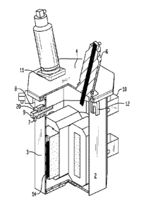
[0025] FIG. 1 illustrates an isometric view of an exemplar polymeric tank
for a
distribution transformer.
[0026] FIG. 2 illustrates an isometric view of a compression belt for
securing a
housing and top cover.
[0027] FIG. 3A illustrates an isometric view the compression belt of Fig.
2
installed between the top cover and the housing and a corresponding side
profile.
Date Recue/Date Received 2021-07-07
86204769
[0028] FIG. 3B illustrates a side view the compression belt of Fig. 2
installed
between the top cover and the housing.
[0029] FIG. 4 illustrates an exemplar polymeric tank with a portion
removed
along reference line A-A of Fig. 1.
[0030] Fig. 5 illustrates a cross-sectional view of a low voltage
terminal along
reference line B-B of Fig. 7.
[0031] FIG. 6 illustrates an isometric and anterior view of the exemplar
polymeric tank with installation support structures.
[0032] Fig. 7 is a side view of the distribution transformer of Fig. 1
[0033] FIG. 8 illustrates a cross-sectional view of the distribution
transformer of
Fig. 7 along reference line C-C without the power components.
[0034] FIG. 9 illustrates a top cross sectional view of the distribution
transformer of Fig. 7 along reference line B-B.
[0035] FIG. 10 is an enlarged view of a circular end plug and mounting
receptacle pair used to secure the power components within the housing.
5a
Date Recue/Date Received 2021-07-07
CA 03076205 2020-03-17
WO 2019/059899
PCT/US2017/052410
[0036] FIG. 11 is an enlarged view of a straight end plug and mounting
receptacle pair used to secure the power components within the housing.
[0037] Fig. 12 is an enlarged view of a T end plug and mounting receptacle
pair used to secure the power components within the housing.
[0038] FIG. 13 illustrates a front view of an exemplar mounting receptacle
without an associated plug.
[0039] FIG. 14 illustrates a side view a mounting receptacle and plug and
housing wall.
[0040] FIG.15 is an isometric view of a straight end plug.
[0041] FIG.16 is an isometric view of a Tend plug.
[0042] FIG.17 is an isometric view of a circular end plug.
[0043] FIG. 18 is a cross sectional view of a wall and associated mounting
receptacle without a plug.
[0044] Fig. 19 is a side view of a straight end plug in a slat form.
[0045] Fig. 20 is side view of a straight end plug in a comb form.
[0046] Fig. 21 is a side view of another variation of a straight end plug
in
comb form.
[0047] Fig. 22 is a cross-sectional view of a shield and housing wall
having
a channel below the surface of the interior wall.
[0048] Fig. 23 is a cross-sectional view of a shield and housing wall
having
a channel above the surface of the interior wall.
[0049] Fig. 24 is a cross-sectional view of a wall and a two layer shield
comprising an exterior mold and an interior layer of permeable material within
the
housing wall.
[0050] Fig. 25 is a cross-sectional view of a wall and a thin layer of a
permeable material attached to the interior wall of a housing.
[0051] Fig. 26 is a cross-sectional view of a wall and a two layer shield
comprising an interior mold and an exterior layer of permeable material within
the
housing wall.
[0052] FIG. 27 is an exploded view of the distribution transformer housing
6
CA 03076205 2020-03-17
WO 2019/059899 PCT/US2017/052410
and shield without the power components.
DETAILED DESCRIPTION
[0053] Reference will now be made in detail to the various embodiments
of this disclosure, examples of which are illustrated in the accompanying
drawings. Wherever possible, the same reference numbers will be used
throughout the drawings to refer to the same or like parts.
[0054] Shown in Fig. 1 is an embodiment of the present invention of a
tank of a distribution transformer 1. It should be understood that the
reference to
a distribution transformer is illustrative and should not be construed as
limiting. It
is well within the scope of the present invention to include any electrical or
power
component requiring the use of the present invention to install, remove,
locate,
secure and maintain such electrical components in place. Moreover, although
exemplary embodiments will refer to gas or fluid-filled tanks, the present
invention
is also applicable to dry type tanks such as dry transformers.
[0055] Fig. 1 illustrates a tank 2 for power components and in
particular,
a tank 2 for a distribution transformer 1. The distribution transformer tank 2
comprising one or more walls 3, a top cover 4, a bottom cover 5, protuberances
20 and protuberances 8. The tank 2 may comprise one continuous wall 3 such
as a circular or elliptical wall 3 or a plurality of walls joined together.
More often,
the tank 2 is configured in a round, rectangular, hexagonal or octagonal
shape. In
the following embodiments, reference will be made to walls 3 due to the
plurality
of sides shown in the figures. The tank 2 is preferably made from a non-
corrosive, non-conductive and non-magnetic material such as various well known
polymers such as plastics and resins which are relatively light weight and
have
considerable structural strength. In particular, and in a preferred embodiment
of
the present invention, the tank 2 is preferably made from polyam ides (PA),
polyesters such as polycarbonate (PC), polybutylene terephthalate (PBT) or
polyoxymethylene (P0M) and other plastic like substances whose characteristics
can be selected and mixed to acquire the necessary strength, flexibility,
insulation, temperature resistance and moldability. More specifically, the
plastic
7
CA 03076205 2020-03-17
WO 2019/059899 PCT/US2017/052410
selected should preferably be oil-resilient, and have a high dielectric and
mechanical resilience.
[0056] In one form of the present invention, walls 3 and the bottom cover
are preferably integrally made as a one piece unit. In the manufacture of the
walls 3 and the bottom cover 5, it is anticipated that a mold be used during
the
manufacturing process to create one unitary piece. In this manner, the unitary
construction will enhance the manufacture of a leak proof tank 2. The top
cover 4
can be later attached to the upper rim of the walls 3 via various connection
techniques such as mechanical fasteners, including but not limited to hinges,
latches, detents, belts, screws, bolts, nuts, rivets, pins, adhesives,
solvents and
various welding techniques.
[0057] For example, the top cover 4 and the rim of the walls 3 can be
joined by fusion bonding in which the top cover 4 and the rim of the walls 3
are
juxtaposed and heat is applied (in various forms) to the joint between the top
rim
of the walls 3 and the top cover 4 in order to plasticize the two parts and
then
allowed to cool to form a bond. And yet still, the top cover 4, may be joined
to the
rim of walls 3 by solvent bonding, vibration and ultrasonic welding, adhesive
welding, and the like. Note that the joining of any part of the tank 2 may be
joined
by any of the above techniques or any other technique. The choice of the means
for joining the top cover 4 with the rim of walls 3 will in large part be
based on the
anticipated environment and expected operational characteristics that may
necessitate the selection of a hermetically sealed or dry type housing.
[0058] For example, if it is anticipated that subsequent access to the
internal active components of the transformer will be needed, reversible means
should be considered, such as bolts and other mechanical fasteners referenced
above which can be removed and then re-installed again. As shown in Fig. 1,
the
top cover 4 and the rim of walls 3 are in one embodiment bolted together by
means of nuts 35 and bolts 36 and/or a belt 30.
[0059] In a preferred method of securing the top cover 4 and the tank 2,
a
compression belt 30 either alone or in combination with other fastening means
such as the nuts 35 and bolts 36 shown in Figs. 3A and 3B may be used. The
compression belt 30 shown in Fig. 2 is preferably made of metal or plastic and
CA 03076205 2020-03-17
WO 2019/059899
PCT/US2017/052410
used to surround the rims of both top cover 4 and walls 3. The compression
belt
30 may also be tightened by using other tightening means such as a latch to
bring both ends of the compression belt 30 together. Preferably however, and
as
shown in Fig 2 the compression belt 30 may be tightened by a nut 35 and bolt
36.
To facilitate removal of the belt, the nut 35 and bolt 36 are spaced apart by
a
compressible spring 37 that will aid in the separation of the compression belt
30
ends when the nut 35and bolt 36 are loosened.
[0060] In an alternative design, top cover 4 and walls 3 are manufactured
as an integral unit, and whereby the power component such as the content of
the
distribution transformer 1 is placed on top of the bottom cover 5. Thereafter
the
top cover 4 and the walls 3 as a unit are placed over the power components and
the bottom cover 5 and the bottom rim of the walls 3 are then joined in
similar
fashion to various joining techniques referenced above or as known to those
skilled in the art. This alternative however, is more applicable to designs
which
incorporate lighter power components that are more maneuverable within the
housing walls 3 and/or which require a dry type housing.
[0061] As further shown in Fig. 1, the top cover 4 comprises one or more
protuberances 11 for securing high voltage bushings 6. The protuberances 11
are preferably made integral or unitary with to the top cover 4. In this
design, the
high voltage bushings 6 of the type shown in Fig. 1 may be joined to the
protuberances 11 in a variety of ways, including but not limited to the use of
threads on the bushings 6, and complementary threads on the inner surface of
the opening of the protuberances 11 (not shown). Moreover, the high voltage
bushings 6 may be joined to the protuberances 11 via flanges (not shown) on
the
high voltage bushes 6 which can then be joined to the top surface of the
protuberance 11 via various fastening techniques as previously described.
[0062] Alternatively, the high voltage bushings 6 may be made integral
with the top cover 4. More specifically, the high voltage bushings 6 may be
set
within a mold used to create the top cover 4. Plastic type material may be
injected within the mold to engulf a portion of the lower part of the high
voltage
bushing 6. The terminals at either end of the high voltage bushings are not
covered by the plastic like material. In this manner, replacement of the high
9
CA 03076205 2020-03-17
WO 2019/059899 PCT/US2017/052410
voltage bushings 6 and the top cover 4 can be completed by the substitution of
an already installed and integrally formed high voltage bushing 6 and top
cover 4.
[0063] To minimize, the potential for electrical discharge between the
high voltage bushings 6, the protuberances 11 and high voltage bushings 6 are
angled away from each other. The protuberances 11 are integrally designed with
the top surface of the top cover 4 to be manufactured in a slanted
orientation.
[0064] On the outer surface of walls 3, one or more side mounts 12 may
be made integral to the walls 3. The side mounts 12 are preferably made of
similar material to walls 3, although depending on the size and weight of the
components within the tank 2, the side mounts 12 can be made of or reinforced
with metal with preferably an insulating coat around the outer surface of the
side
mounts 12. In Fig. 1 the shape of the side mounts 12 is an inverted U,
although it
should be noted that these side mounts 12 may be made in various shapes to
accommodate the lifting and movement of the distribution transformer. For
example, the side mounts 12 may take the shape of 0 rings or T shaped
protrusions that may easily engage with positioning cables.
[0065] These side mounts 12 function as a means of transport and
means of installing the distribution transformer 1. Moreover, they may also
function as a means of further securing the distribution transformer 1 in
place by
using the side mounts 12 as an attachment point for attaching a securing line
between the distribution transformer 1 and a pole.
[0066] In addition to the high voltage bushings 6, the outer surface of
the
walls 3, may accommodate one or more low voltage terminals 9 (secondary
terminals) for connection to a low voltage power line used to feed power to a
consumer. The low voltage terminals 9 may be positioned anywhere on the outer
surface of the walls 3, although by convention and under certain circumstances
in
compliance to local regulatory standards, these low voltage terminals 9 are
preferably placed at the front of the distribution transformer tank 2 and at
sufficient distances from each other so as to render access to these low
voltage
terminals 9 to be in a safe and accessible manner.
CA 03076205 2020-03-17
WO 2019/059899
PCT/US2017/052410
[0067] It should be noted in one embodiment of the present invention, the
connection point of the low voltage terminals 9 with the tank 2 occurs by way
of a
threaded protuberances 20. As shown in Figs. 4 and 5, protuberances 20 are
preferably integral to the walls 3 of the tank 2. In the present embodiment
three
protuberances 20 are positioned at the upper front outer portion of wall 3. A
conductor 31 is placed through an opening of a screw cap 8 and the screw cap 8
is then screwed onto the threaded protuberance 20 so as to form a tight seal.
The
seal between the screw cap 8 and the protuberance 20 is further enhanced by
the use of optional 0 rings (not shown) between the screw cap 8 and the
protuberance 20.
[0068] Alternatively, the protuberance 20 may comprise a socket within
the opening of protuberance 20. The socket may be made of metal and
configured to mate with the outer lower surface of a low voltage terminal 9 as
are
known in the industry. The mating of the low voltage busing 9 and protuberance
20 are may be of the type known as plug and socket bushings. The bushings 6
and low voltage terminals 9 may be connected to the top cover 4 and walls 3 by
any of the above connecting techniques such as threads, flanges and plug and
sockets. Moreover, the low voltage terminals 6 may likewise be molded into the
walls 3 as were described above with reference to the bushings 6 and
protuberances 11.
[0069] Pole brackets 13 (see Fig. 6) are primarily used in the event that
the tank 2 is being placed on a pole without a base platform. Platforms
installed
power components such as distribution transformers 1 may be located on the
ground or a platform above the ground that is attached to a pole. In such
platform installations, the pole brackets 13 are not necessary, although in
many
cases such pole brackets 13 are nevertheless used to further secure heavier
loads on the pole.
[0070] Shown in Fig. 4 is a sectional view of the distribution
transformer 1
of Fig. 1 along 90 degree reference line A-A. The exposed section of the
distribution transformer 1 shows the windings 22 and core 21 of the
distribution
transformer 1. In addition, Fig. 4 shows a side view of a mounting receptacle
14
on the inner surface of walls 3. As will be detailed infra, the use a mounting
11
CA 03076205 2020-03-17
WO 2019/059899
PCT/US2017/052410
receptacle 14 is used as a positioning and securing means for the installation
of
the core 21 and windings 22 of the distribution transformer 1 as well as other
power components. Alternatively and depending on the equipment to be installed
in tank 2, one or more mounting receptacles 14 may be used to position and
secure the power components. Furthermore, the mounting receptacle 14 may be
used as a guide to install an electromagnetic shield 18. The details of the
mounting receptacle and corresponding plug(s) 15 will be further discussed
below.
[0071] Shown in Fig. 6 is a rear view of the distribution transformer 1
with
pole brackets 13 mounted on the support strap 7. Support strap 7 in the
embodiment shown in Fig. 6, is configured in an L-shape to provide structural
strength and support to the tank 2. The support strap 7 may be made from
various materials, provided they can provide the structural strength necessary
to
support the weight of the housing, dielectric fluids, and the internal and
external
components attached thereto.
[0072] In a preferred embodiment the support strap 7 is made from
preferably a metal such as steel and coated with an insulating layer such as
silicone, plastic, or resin. The coating is intended to protect the supporting
strap 7
from conducting a current and from the environment. Alternatively, and if the
weight of the components to be included in the tank 2 is not excessive, the
support strap 7 may be made of a non-conductive, non-corrosive, and non-
magnetic material such as the polymers referenced above with respect to the
composition of the tank 2. Should the support strap 7 be made of the same
material as that of the tank 2, the support strap 7 is preferably made
integral with
the tank 2.
[0073] The support strap 7 may be installed by inserting the end of a
vertical leg 23 into a slot 26 of a back stop 27. The back stop 27 may be made
of metal or any other material capable of securing the end of the vertical leg
23.
In Fig. 6, the end of the vertical leg 23 may be secured to the back stop 27
by a
myriad of fastening means such as screws, plugs, nuts, bolts, pins, and rivets
etc.
Preferably, the back stop 27 may be made of the same material as walls 3 and
be manufactured as an integral part of wall 3 and bottom cover 5.
12
CA 03076205 2020-03-17
WO 2019/059899
PCT/US2017/052410
[0074] The horizontal leg 24 of the support strap 7 may likewise be
secured to the bottom cover 5, by the use of any of the fastening means
referenced above. Alternatively, the bottom cover 5 may include a bottom cover
projection 28 that enters a hole 32 or opening in the horizontal leg 24 of the
support strap 7. The bottom cover projection 28 is preferably engaged to the
hole 32 of the horizontal leg 24 in a friction fit manner. If other support
straps 7
are used, the length of bottom cover projection 28 may need to be extended to
accommodate additional support straps 7.
[0075] In an alternate embodiment, the tank 2 may be supported by more
than one support strap 7, placed about the circumference of the bottom cover
5.
For example, a second support strap 7 may be positioned at 90 degrees to the
left or right of the support strap 7 shown in Fig. 3. The addition of other
support
straps 7 enhances the structural strength of the housing while securing the
housing and internal power components in place. Corresponding back stops 27
should be added to the outer surface of walls 3 for each additional support
strap
7 used.
[0076] Fig. 7 is a side view of the distribution transformer 1 of Fig. 1.
Fig
8 is cross sectional view of Fig. 7 along the reference plane C-C without the
power components. Mounting receptacle 14 and plug 15 are shown on the left
and right walls 3. The center wall 3 comprises a mounting receptacle 14
without
the associated plug 15 to better view channel 16 and ridges 29.
[0077] Fig. 9 shows a top cross sectional view of distribution
transformer
1 of Fig. 7 along the plane of reference B-B. Shown are the core 21 and
windings 22 of the distribution transformer 1 and the use of three (3)
mounting
receptacles 14 and plugs 15 (14a-c, 15a-c in Figs. 10-12) to position and to
secure the power components of the distribution transformer 1 in place. For
illustration purposes, each of the three (3) mounting receptacles 14a-c and
plugs
15a-c are configured with a different geometric designs- although similar or
dissimilar geometric designs may be used to secure power components within
the tank 2.
[0078] The mounting receptacle 14 and the plug 15 serve two primary
functions. During a preferred method of installation of the power components,
13
CA 03076205 2020-03-17
WO 2019/059899 PCT/US2017/052410
the bottom cover 5 and the walls 3 already contain the power components to be
enclosed. The plug(s) 15 are thereafter inserted within channel(s) 16 and are
lowered into place such that the longitudinal sides of the plugs 15 either
contact
or almost contact the power components. Under these circumstances, the power
components, may move slightly or not at all. Depending on the clearance or
spacing available between the channels 16 and the power components, the plugs
15 may need to be inserted with minimal effort or with some applied force. In
some cases, the plugs may be pounded with a hammer to ensure a snug fit. In
such a manner the plug(s) 15 and mounting receptacle(s) 14 serve to properly
secure the power components into the distribution transformer housing.
[0079] Alternatively, the plugs 15 may be attached to the power
components before installation into the tank 2. The plugs 15 are positioned
along the exterior surface of the power components and may be attached to
frames or supporting structures of the power components. In such a manner, the
mounting receptacles 14 and the plugs 15 not only serve as a means for
securing
the power components but also, serve as a means for guiding the installation
of
the power equipment within the walls 3 and bottom cover 5. The plugs 15 are
positioned into corresponding channels 16 and lowered. Once installed, the
mounting receptacle 14 and plug 15 serve to lock in place such power
components to minimize or prevent movement. Accordingly, such an
arrangement tends to minimize or prevent the potential hazard of having active
power components coming into contact with each other.
[0080] Embodiments of the mounting receptacle 14 and plug 15 pairs are
shown in Figs. 10-12. The plug 15 and corresponding mounting receptacle 14
are configured to mate with each other by preferably having complementary
contours such that the shape of the plug 15 fits within the surface of channel
16.
As shown in Figs. 9-14, channel 16 is created between two raised sections or
ridges 29 from the inner surface of the walls 3. Preferably the two ridges 29
are
made from the same material and are integral to the inner surface of walls 3.
As
such, one or more mounting receptacles 14 may be used within each tank 2.
[0081] Complementary to the mounting receptacle 14 is a corresponding
mating plug 15. The plug 15 may take the form of various shapes depending on
14
CA 03076205 2020-03-17
WO 2019/059899 PCT/US2017/052410
the desired function. (see Figs 10-12 and Figs. 15-17) Plug 15 is preferably
configured in the form of a vertical slat which can mate with the walls of
channel
16 although plug 15 may also be configured in a comb like fashion wherein one
or more teeth 33 may be used to mate with channel 16 of mounting receptacle
14. (see Figs. 20 and 21). Preferably plug 15 is made from a non-corrosive,
non-
conductive and non-magnetic material such as various well-known polymers such
as plastics and resins which are relatively light weight and have considerable
structural strength.
[0082] The plug 15 is in an alternate embodiment connected to the
winding 22, core 21, or other power component by attaching the plug 15 to a
frame, mandrel or support structure attached to the power components, or some
other device which can support and connect the plug 15 to the frames or
supporting structures of the power components of the distribution transformer
1.
As a consequence, the pre-attached plugs 15 to the power components may
function not only as a securing means, but a means to guide in the placement
or
installation of the power components in the tank 2.
[0083] To secure the power components in place, the outer surface of the
plug 15 should substantially correspond to the inner mating surface of channel
16
between ridges 29 to create a locking fit between the plug 15 and the mounting
receptacle 14. As shown in Figs. 10-12, the plug 15 and channel 16 may take
complimentary forms such as a "T" end ( 15c Fig. 12) or circular end (15a Fig.
10)
or straight end (15b Fig. 11) configuration. It should be understood however
that
the geometric shape of the plug 15 and channel 16 should not be limited by the
specific shapes shown herein. Any shape capable of creating a complimentary
fit
between the plug 15 and channel 16 may be used. Shown in Figs. 15-17, are the
three dimensional slat versions of the plugs 15 of shown in Figs 11-12.
[0084] Fig. 18 shows a side view of mounting receptacle 14 without a
corresponding plug 15. The plugs 15 as shown in Figs. 19-21, are
configurational variations to the geometries already shown in Figs. 9, and
Figs
10-12. Although the slat shape of plug 15 in Fig. 19 is a preferred slat
configuration, the plug 15 may alternatively incorporate the use of
projections or
teeth 33 (Figs. 20-21) to mate with a complementary shaped channel 16. The
CA 03076205 2020-03-17
WO 2019/059899 PCT/US2017/052410
teeth 33 of Figs. 20-21 may incorporate the T, circular or straight
configuration of
slat plugs 15 of Fig 15-17 or any other end configuration.
[0085] Alternatively, and as shown in Fig. 22 and depending on the
thickness of the walls 3, the mounting receptacle 14, can be made by the
creation
of a channel 16 below the interior surface of the walls 3, by either removing
material from the channel after manufacture or by having the walls 3 molded
with
a channel 16 created below the interior surface of walls 3 during the
manufacturing process.
[0086] Shown in figure 27 is an exploded view of walls 3 and an
insertable barrier or shield 18. The shield 18 is used to keep or minimize the
electromagnetic field ("EMF") outside of the tank 2. To achieve such EMF
shielding, shield 18 may be comprised of metallic substances having a high
degree of permeability such as nickel, iron, copper, chromium, molybdenum,
gold, aluminum, steel, silicon steel or any combination thereof. For example,
a
known shielding material is the use of sheets of mu-metal alone or in
combination
with other materials. Mu-metal is a nickel-iron soft magnetic alloy with a
very
high permeability which is well known for its ability to shield electronic
equipment
from static or low-frequency magnetic fields.
[0087] The shield 18 in Fig. 23 may be made from such highly permeable
material such as mu-metal alone or in combination with other materials capable
of providing the structural strength necessary to allow the shield 18 to be
inserted
into tank 2 during the manufacturing process. A single solid structure of
shield 18
may be inserted inside walls 3. The channel 16 is preferably integral to the
interior surface of the walls 3 and formed from a pair of ridges 29 above the
surface of the interior walls 3.
[0088] In another embodiment, and as shown in Fig. 25, a thin sheet or
layer of highly permeable material such as mu-metal may be applied and joined
or fused to the interior surface of the walls 3. This may take the form of a
foil, a
metallic net, strands of metal or other conductive material capable of
shielding
the environment outside the tank. On the other hand, and as shown in Fig. 26
the highly permeable material may be applied to the outer surface of a mold 34
in
the form of shield 18 made of non-corrosive, non-conductive, non-magnetic
16
CA 03076205 2020-03-17
WO 2019/059899
PCT/US2017/052410
material. In effect the shield 18 would comprise a two layer configuration as
shown in Fig. 26 in which a mold 34 is used as a base to apply a layer of
highly
permeable material such as mu-metal. The mold 34 may be plastic or other
desirable material and serves as structural support for permeable material
unable
to provide the structure strength necessary to be fitted within tank 2. In
similar
manner, the shield 18 may be placed on the interior surface of mold 34 as
shown
in Fig. 24.
[0089] The shield
18 in Fig. 27 may be made in various ways and should
be substantially congruent to the interior shape of the tank 2. The shield 18
may
have one or more slits 19 as a means of mounting the shield 18 to the interior
surface of the tank 2. The shield 18 may be lowered inside the tank 2 with
corresponding slits 19 being positioned such that the slits 19 are wide enough
to
accommodate the perimeter of the mounting receptacle 14. In a preferred
embodiment, the slits 19 are complimentary in perimeter to the exterior
perimeter
of the mounting receptacle 14.
[0090] In a
preferred embodiment of the invention, shield 18 is preferably
comprised of slits 19 corresponding to the number of mounting receptacles 14.
In the embodiment shown in Fig. 8, three (3) mounting receptacle 14 and plug
15
pairs are shown. In Fig. 27 however, tank 2 is configured as an eight (8)
sided or
walled housing, with only 6 mounting receptacle 14 and plug 15 pairs. Two of
the sides or walls 3 do not include a mounting receptacle 14 and plug 15
pairs.
The selection of the number of mounting receptacle 14 and plug 15 pairs is a
matter of design choice based on the type of power components and dielectric
to
be housed. In certain instances, one mounting receptacle 14 and plug 15 pair
can be used for each available segment of the housing walls 3. In some cases,
the unused walls space as shown in Fig. 15 may be installed with additional
mounting receptacle 14 and plug 15 pairs. Each additional pair may be used to
secure and install other power components that are peripheral to the main
power
components such the core and windings.
[0091] The present
disclosure provides, to one of ordinary skill in the art,
an enabling description of several embodiments and/or inventions. Some of
these
embodiments and/or inventions may not be claimed in the present application,
17
CA 03076205 2020-03-17
WO 2019/059899
PCT/US2017/052410
but may nevertheless be claimed in one or more continuing applications that
claim the benefit of priority of the present application.
[0092] The foregoing description discloses only exemplary embodiments
of the invention. Modifications of the above disclosed embodiments which fall
within the scope of the invention will be readily apparent to those of
ordinary skill
in the art. For example, although the examples discussed above are illustrated
for a power transmission and distribution market, embodiments of the invention
can be implemented for other markets.
[0093] Accordingly, while the present invention has been disclosed in
connection with exemplary embodiments thereof, it should be understood that
other embodiments may fall within the spirit and scope of the invention, as
defined by the following claims.
18