Note: Descriptions are shown in the official language in which they were submitted.
CA 03076328 2020-03-18
WO 2018/070870 PCT/NL2017/050667
1
Title: Retractable deck pin
The present invention relates to a retractable deck pin. The retractable deck
pin is a marine
pin which is mountable at a deck of a vessel and which is arranged to
cooperate with a boat
line, e.g. a rope or a chain. The deck pin can be elevated above a deck level
of a vessel and
retracted again. A retractable deck pin may be arranged as a tow line guide
pin, an
anchoring point or a retractable cleat.
US 4.603.649 discloses a retractable tow line guide pin at a stern of a
tugboat or supply
boat which is made to be elevated from or to be retracted into the deck of the
vessel. The
retractable guide pin comprises a cylindrical pin body which has a pin top and
a pin base.
The pin top is provided with a projecting locking member for closing an
opening between two
side-by-side positioned guide pins. In use, the locking members prevent a boat
line to
escape from the guide pins. The pin bodies with locking members are rotatable
to close the
opening in between two guide pins. Additionally, the pin body is axially
movable to retract or
elevate the pin top with respect to the deck of the vessel. To allow the
movements of the in
body, the pin body is guided by a pin guidance which circumvents the pin body.
The axial
movement of the pin body is controlled by an hydraulic cylinder. The hydraulic
cylinder is
positioned below the deck.
A drawback of the disclosed retractable tow line guide pin is that seawater
may leak below
deck level through a clearance in between the pin body and the pin guidance.
Leaking
seawater passes along underdeck components which causes corrosion and limits
an
operational lifetime of the guide pin.
US 6.588.355 discloses a retractable cleat including an underdeck retainer.
The retainer is
shaped to allow received leaked seawater to be drained therefrom. The shape of
the
retainer allows for a complete drainage of an interior to reduce a possible
corrosion of
components.
W02013/077742 discloses a similar solution regarding an anchoring point in a
helicopter
deck. The anchoring point contains a fastener which is retractable into a
housing. A bottom
portion of the housing is provided with a drainage opening leading into a
discharge conduit
which is arranged to lead fluid away from the housing. Accumulation of fluid
in the housing is
CA 03076328 2020-03-18
WO 2018/070870 PCT/NL2017/050667
- 2 -
prevented. A penetration fluid into the housing is drained away in order to
avoid corrosion
and freezing of components of the anchoring point.
US 5.983.820 discloses a retractable cleat including an improved seal. The
seal is arranged
to prevent water from seeping into tubes of a base. The seal is configured to
form a
watertight seal about a post depending from a head of the retractable cleat.
The seal is
press-fit within a seat of the base, such that an exterior surface and a
bottom surface of the
seal is in substantial contact with an interior wall and step wall of the
seat. The seal is an
annularly shaped seal having an interior surface for closely receiving the
post, but being
configured to permit the post to slide longitudinally.
A drawback of this disclosed seal is that this solution does not satisfy. To
much seawater still
leaks and passes the seal of the retractable cleat which causes problems of
corrosion.
The general object of the present invention is to at least partially eliminate
the above
mentioned drawbacks and/or to provide a useable alternative. More specific, it
is an object
of the invention to provide a retractable deck pin which reduces a leakage of
seawater
through a deck of a vessel.
According to the invention, this object is achieved by a retractable deck pin
according to
claim 1.
According to the invention, a retractable deck pin is provided which deck pin
is arranged for
cooperating with a boat line, like a rope or a chain. In an embodiment, the
retractable deck
pin is a tow line guide pin which is arranged for guiding the boat line. In an
embodiment, the
retractable deck pin may be a retractable cleat or an anchoring point.
The retractable deck pin comprises a cylindrical pin body which defines an
axial axis. The
pin body is arranged in an upper region of the deck pin. The pin body has a
pin base and a
pin top. The pin top is configured to cooperate with the boat line.
The retractable deck pin comprises a pin guidance for axially guiding pin
body. The pin
guidance allows the pin body to move up and down in the axial direction. The
pin guidance
has a cylindrical inner space for receiving the pin body. The pin body is
axially movable
inside the inner space. The pin base is received in the inner space.
CA 03076328 2020-03-18
WO 2018/070870 PCT/NL2017/050667
- 3 -
The retractable deck pin comprises at least one seal element. The seal element
is
positioned in the inner space for sealing the pin body with respect to the pin
guidance. The
seal element is a ring shaped and seals a clearance in between the pin body
and the pin
guidance.
The retractable deck pin comprises an actuator, in particular a hydraulic
cylinder. The
actuator is positioned in a lower region of the deck pin. The actuator is
connected to the pin
body for axially moving the pin body with respect to the pin guidance.
According to the invention, the retractable deck pin is improved by providing
a liquid
reservoir. The reservoir is arranged for containing a liquid volume.
Preferably, the liquid
volume is an oil volume. The reservoir is positioned in the lower region of
the deck pin. The
reservoir is arranged for enclosing underdeck positioned components of the
deck pin. The
reservoir comprises a reservoir wall which circumvents the actuator. The
reservoir comprises
a reservoir bottom. The reservoir bottom is positioned below the pin guidance
and below the
pin base. The reservoir has a reservoir opening for receiving the pin base in
the contained
liquid volume.
Further, the deck pin includes an air inlet which is provided with an air
valve. Preferably, the
air inlet is a passageway provided in the reservoir wall. Alternatively, the
air inlet may be
formed by a passageway in a pin guidance wall. Preferably, the air inlet
provides a
passageway in between an ambient environment and a reservoir inner space.
Preferably, the air valve is a pneumatic non-return valve, or so called
pneumatic one-way
valve. The air valve is arranged to allow an air flow into the reservoir, and
to block an airflow
out of the reservoir. Alternatively, the one-way valve may be an operatable
valve.
In operation of the retractable deck pin, the pin base is axially moved with
respect to the
contained liquid volume in the reservoir. When moving the pin base into the
liquid volume, a
liquid level of the contained liquid volume will rise and an air volume above
the liquid volume
will get pressurised. The air valve prevents an escape of an air via the inlet
of the reservoir.
As a consequence, an airflow can only escape from the reservoir via the
clearance in
between the pin body and the pin guidance. Advantageously, the upwardly
directed airflow
through the clearance in between the pin body in the pin guidance counteracts
a possible
incoming flow of leaking seawater which may move downwardly together with the
pin body.
CA 03076328 2020-03-18
WO 2018/070870 PCT/NL2017/050667
- 4 -
Preferably, the reservoir is arranged for completely enclosing the actuator of
the deck pin.
Preferably, the reservoir bottom is positioned below an actuator housing of
the actuator,
such that the actuator housing is completely received in the reservoir. The
reservoir wall or
reservoir bottom may be provided with at least one port to allow a passage of
an actuator
conduit to the actuator housing for operating the actuator. Advantageously, a
complete
enclosure of the actuator by the reservoir allows a simple structure in which
additional
sealing items can be avoided. In an alternative embodiment, the actuator
housing may
extend through the reservoir bottom.
The at least one seal element in the clearance in between the pin body and the
pin guidance
is arranged to provide a watertight seal. In the prior art, applied seal
elements are arranged
to provide a watertight sealing during a rotational movement of the pin body.
It has appeared
that these watertight seal elements are especially vulnerable for a seawater
leakage during
the axial movement of the pin body. Damages at an outer surface of the pin
body, like
crashes and grooves, which may be caused by a boat line impact increase a
seawater
leakage through the clearance between the pin body and pin guidance along the
at least
one seal element. Advantageously, the counter acting airflow during a lowering
of the pin
body blows leaking seawater backwards along the pin body in an upwards
direction towards
the pin top to prevent the seawater arriving under the deck. Advantageously,
the presence
of the air inlet allows a supply of air when the pin body moves upward and
prevents a
sucking of an airflow along the pin body in a downwards direction which
prevents a sucking
of seawater through the clearance. Herewith, the retractable deck pin
according to the
invention provides an improvement in a resistance against a seawater leakage.
In an embodiment of the retractable deck pin according to the invention, the
at least one
seal element is a one-way airtight seal element. The seal element is
positioned in the
clearance in between the pin body and the pin guidance, such that an air flow
is permitted in
an upwards direction along the pin body and prevented in a downwards direction
along the
pin body. An example of such a one-way airtight seal element is a seal element
according to
DIN 3760/3761, e.g a rubberised metal cased open seal element with seal and
dust lip.
When the pin body moves upward, a temporary under-pressure will be generated
in the
reservoir. The one-way airtight capacity of the seal element advantageously
contributes to
prevent a false airflow from the ambient through the clearance in between the
pin body and
the pin guidance. In preventing such a false airflow, it is prevented that
also seawater is
sucked together with ambient air along an outer circumference of the pin body
into the
reservoir. Hence, the one-way airtight capacity of the seal element supports a
sucking of
ambient air only through the air inlet.
CA 03076328 2020-03-18
WO 2018/070870 PCT/NL2017/050667
- 5 -
In particular, the one-way airtight seal element is an asymmetric seal element
which
asymmetric shape is formed by an axially extending sealing lip. In particular,
the seal
element is a metal cased seal element in which the seal element includes a
metal case body
at an outer circumference. More in particular, the seal element is an open
metal cased seal
element in which the seal element includes an axially open metal case body at
an outer
circumference. The seal element comprises at an inner circumference a seal lip
which
provides the airtight capacity. Preferably, the seal element comprises at an
inner
circumference a seal lip and a dust lip. Preferably, the lubrication of the at
least one seal
element is carried out by greasing which may further improve the airtight
capacity of the seal
element.
In an embodiment of the retractable deck pin according to the invention, the
at least one
seal element is a lower seal element. The lower seal element is positioned at
a lower region
of the pin guidance. The lower seal element is positioned, such that in
operation of the deck
pin only an outer circumferential surface of the pin base contacts the seal
element. The
outer circumferential surface of the pin base is a surface which remains free
from boat line
impacts and for that reason may remain free from damage. The outer
circumferential
surface of the pin base may remain a smooth surface which contributes to a
proper sealing.
The smooth outer surface of the pin base is suitable as a counter surface for
the airtight seal
element.
In an embodiment of the retractable deck pin according to the invention, the
deck pin
comprises at least a lower and an upper seal element, wherein the lower seal
element is a
one-way airtight seal element. All seal elements may be one-way airtight seal
elements, but
preferably only the lower seal element is a one-way airtight seal element. In
an embodiment,
only the lower seal element is a one-way airtight seal element, while each
remaining seal
element is a watertight seal element without an extending sealing lip. Such a
watertight seal
element may include a ring case body at an outer circumference and a symmetric
ring seal
at an inner circumference of the case. The ring seal may have a circular or
block shaped
cross-section.
In an embodiment of the retractable deck pin, the reservoir is formed by
separately
mountable reservoir segments. In particular, the reservoir wall is formed by a
stack of ring-
shaped reservoir wall segments. Advantageously, the reservoir segments allow
an
installation of the reservoir in narrow under deck spaces. Especially,
tugboats often provide
only a small mounting space underneath their deck.
CA 03076328 2020-03-18
WO 2018/070870 PCT/NL2017/050667
- 6 -
In an embodiment of the retractable deck pin, the reservoir is formed by a
reservoir bottom
segment and a stack of reservoir wall segments. Preferably, the reservoir wall
has a height
which corresponds with a mounting height of under deck components of the deck
pin, such
that the components can be fully enclosed by the reservoir.
Further, the invention relates to a deck pin arrangement, wherein the
arrangement includes
a winch for handling a line. Such arrangements can be used as an active tool
during anchor
handling in anchoring of offshore installations and also on tugboats and at
other tugging
operations. Particularly boat lines, like large-diameter ropes or hawsers, are
to be guided on
all sides in a guide passage which, however, must be capable of being opened
for insertion
and removal of this rope from the passage. It is particularly advantageous on
board ship,
especially as a guide at the stern of a tug. In such an application the guide
arrangement is
mounted midships at the stern of the tug in the region of the bulwark.
Further, the invention relates to a guide pin arrangement which includes at
least two, in
particular three retractable guide pins. In particular, the guide pin
arrangement is a tow line
guide pin arrangement to be installed on board of a tugboat, a so-called
tugboat tow line
guide pin arrangement.
In an embodiment of the tugboat tow line guide pin arrangement, the guide pin
arrangement
comprises a pair of side-by-side positioned guide pins, which guide pin each
includes a pin
body with a lock element positioned at an end face of a pin top, wherein the
lock element is
movable to close an opening in between the two guide pins. The tugboat tow
line guide pin
arrangement includes a pair of lock elements, also called "flaps", - as
vertical stoppers -on
top of the pin bodies. Generally, the tugboat tow line guide pin arrangement
is positioned at
a stern of the vessel. Each guide pin is pivotable to permit the lock elements
to be brought
by rotation into a locking position, such that a towline is captured in
between the guide pins
and lock elements. A vertical movement of the towline or similar means is
limited by the lock
elements.
Further, the invention relates to a vessel, in particular a tugboat comprising
a deck and at
least one retractable deck pin according to the invention.
Further, the invention relates to a method for operating a retractable deck
pin comprising the
steps of providing a deck pin according to the invention; filling the
reservoir of the deck pin
with a liquid volume; actuating an upwards or downwards movement of the pin
body of the
deck pin.
CA 03076328 2020-03-18
WO 2018/070870 PCT/NL2017/050667
- 7 -
Further, the invention relates to a method of revising an existing retractable
deck pin to
reduce seawater leakage. The revising method comprises the step of mounting a
reservoir
over under deck positioned components. The reservoir is mounted below the pin
guidance
and pin base of the deck pin. The mounted reservoir includes an air inlet at
the upper region
of the reservoir wall, which air inlet is provided with an air valve.
The invention will be explained in more detail with reference to the appended
drawings. The
drawings show a practical embodiment according to the invention, which may not
be
interpreted as limiting the scope of the invention. Specific features may also
be considered
apart from the shown embodiment and may be taken into account in a broader
context as a
delimiting feature, not only for the shown embodiment but as a common feature
for all
embodiments falling within the scope of the appended claims, in which:
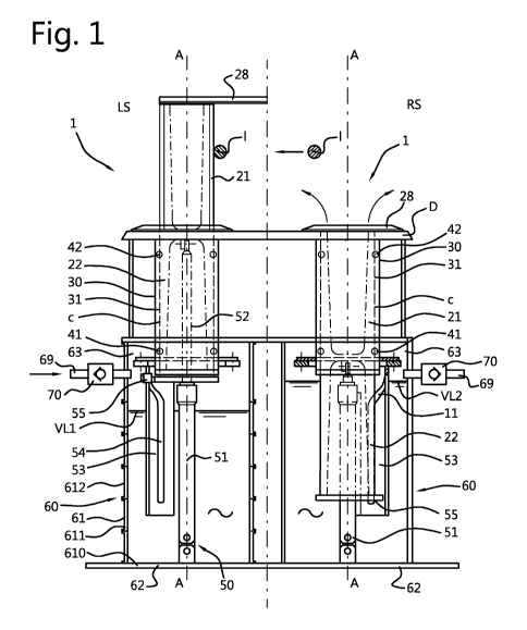
Fig. 1 shows in a cross sectional view a pair of two retractable deck pins
according
to the invention, in which a left sided part of Fig. 1 shows a deck pin in an
elevated
position and a right side part of Fig.1 shows a deck pin in a retracted
position; and
Fig. 2 shows a cross sectional view of a one-way airtight seal element
including a
axial extending seal lip.
Identical reference signs are used in the drawing to indicate identical or
functionally similar
components.
To facilitate comprehension of the description and of the claims the words
vertical,
horizontal, axial, longitudinal, cross-sectional ¨ with reference to gravity¨
are used in a non-
limiting way.
Fig. 1 shows a cross sectional view of a pair of retractable deck pins 1. The
retractable deck
pin is a marine pin which is arranged for operation on board of a vessel.
Here, the illustrated
retractable deck pin is embodied as a tow line guide pin. In a left-sided part
LS, fig. 1 shows
a retractable deck pin in an elevated position and in a right sided part RS,
fig. 1 shows a
retractable deck pin in a retracted position. In the elevated position, the
deck pin is
operational, e.g. for guiding a line I. In the retracted position, the deck
pin is stored in a deck
D of a vessel.
Each deck pin 1 extends along an axial axis A-A. The deck pin 1 comprises a
pin body 20.
The pin body 20 defines the axial axis A-A. The pin body 20 is cylindrical and
has a pin top
CA 03076328 2020-03-18
WO 2018/070870 PCT/NL2017/050667
-8-
21 and pin base 22. The pin top 21 is provided with a lock element 28. The
lock element 28,
also called a flipper, is arranged for closing and opening in between two
neighbouring guide
pins. The lock element 28 is oblong and mounted at a proximal side at an end
face of the
pin body 20. The lock element 28 has a free distal end. In a closed position,
the lock
element 28 is rotated from an initial position, such that two distal ends of
two neighbouring
guide pins contact each other to prevent a tow line I from escaping away from
the guide pin.
The pin body 20 is positioned in a cylindrical inner space 31 of a pin
guidance 30. The pin
body 20 is axially movable with respect to the pin guidance 30. The pin
guidance 30 is
arranged for guiding the pin body 20. A clearance in between the pin body 20
and the inner
space 31 is provided to allow an axial movement of the pin body 20.
At least one seal element 40 is provided to seal the clearance. Here, a lower
seal element
41 is positioned at a lower region of the inner space 31 and an upper seal
element 42 is
provided at an upper region of the inner space 31. The lower seal element 41
is substantially
in contact with an outer circumferential surface of the pin base 22, while the
upper seal
element 42 is substantially in contact with an outer circumferential surface
of the pin top 21.
The outer circumferential surface of the pin top 21 is relatively more
vulnerable to damages
because this surface is in operation in contact with the boat line I.
Scratching of the line
impairs the outer circumferential surface of the pin top 21. The
circumferential outer surface
of the pin base 22 may remain free of damages and provide a smooth surface
which
contributes to a proper sealing.
The deck pin 1 further comprises a pin actuator 50. Here, the actuator is a
hydraulic cylinder
including a cylinder housing 51 and a movable piston rod 52. The cylinder
housing 51 is
stationary connected to the deck D. The piston rod 52 has a free end which is
connected to
the pin body 20.
To force the pin body 20 to rotate, the pin actuator 50 may comprise a tubular
plate shaped
segment 53 which includes a guide groove 54 extending in the axial direction
and which
groove cooperates with a roller stud 55. The roller stud 55 is connected to
the pin base 22.
The guide groove 54 follows a straight line over a substantial portion of his
length, for
example 60 cm or more, while the groove is laterally deflected over the
remaining 20 cm of
its length, assuming the pin body can be moved a total distance of 80 cm. The
deflected part
of the groove is of sufficient angle of inclination and length to cause the
pin body 20, by
means of the roller stud 55 which follows the groove configuration as the pin
body is
elevated, to pivot about 90 from an initial position in which the locking
element is 28 is flush
CA 03076328 2020-03-18
WO 2018/070870 PCT/NL2017/050667
- 9 -
with the deck D shown in the right sided view RS to the closed position of the
locking
element 28 shown in the left-sided view LS of fig. 1.
The deck pin 1 according to the invention comprises a reservoir 60 for
containing a liquid
volume VL, in particular an oil volume. The reservoir is filled with liquid to
a certain liquid
volume level VL1, VL2. The reservoir comprises a reservoir wall 61 which
circumvents the
actuator 50. The reservoir comprises a reservoir bottom 62. The reservoir
bottom 62 is
positioned below the pin guidance 30 and pin base 22. Here, the cylinder
housing 51 is fixed
to the reservoir bottom 62. The reservoir 60 is open at an upper region for
receiving the pin
base 22. The reservoir wall 61 forms the reservoir opening 63.
As illustrated in the left-sided view LS of fig. 1, the reservoir 60 is
mounted by a plurality of
reservoir segments 610,611,612 etc. Reservoir segments are stacked to form the
reservoir
wall 61. A reservoir bottom segment 610 forms the reservoir bottom 62. Ring-
shaped first,
second, third etc. reservoir segments form the reservoir wall 61. The
reservoir segments
may each have a mounting flange for mounting the reservoir segments to each
other.
Advantageously, the reservoir out of segments allow an installation of the
reservoir in narrow
spaces.
The reservoir 60 comprises an air inlet 69 to allow an air flow to enter the
reservoir. The air
inlet 69 is positioned above a level of the liquid volume VL2 when the pin
body is in the
retracted position. Here, as illustrated, the air inlet 69 is positioned at
the reservoir wall 61.
Alternatively, the air inlet may be positioned at the pin guidance in which
the air inlet is
preferably positioned below the lower seal element 41. The air inlet may be
formed by a
bore through a pin guidance wall, in which the bore provides a passageway in
between the
ambient air and a reservoir inner space.
The air inlet 69 is provided with an air valve 70. The air valve 70 is a non-
return valve which
allows an air flow to enter the reservoir, but which non-return valve prevents
an air flow out
of the reservoir 60. Herewith, the non-return valve 70 allows an air flow to
enter the reservoir
60 when the pin body 20 moves upwards, but prevents an air flow out of the
reservoir 60
when the pin body 20 moves downwards. When the pin body 20 moves downwards,
pressurised air can only escape via a clearance 'c' in between the pin body
and the pin
guidance. The air flow through the clearance 'c' away from the reservoir
prevents seawater
from passing through the clearance in an opposite direction to the reservoir.
Herewith,
advantageously, a reduction of seawater leakage is provided.
CA 03076328 2020-03-18
WO 2018/070870 PCT/NL2017/050667
- 10 -
Fig. 2 shows a cross sectional view of a one-way airtight seal element 40. The
seal element
has a case body 46 which forms an outer circumference of the seal element.
Preferably, the
case body 46 includes a metal case. The metal case has an L-shape in cross-
section. The
case body 46 is open at one side. The open side of the case body 46 may be
filled with
grease to increase an operational lifetime of the seal element.
The one-way airtight seal element has an asymmetric shape. The asymmetric
shape is
formed by an axial extending seal lip 47. The seal lip is positioned at an
inner circumference
of the seal element. The seal lip 47 provides the airtight capacity. In the
deck pin, the seal lip
47 of the seal element 40 is extending in upwards direction towards the pin
top 21. An
airflow originating from the reservoir 60 may lift the seal lip 47 from it
counter surface, while
an under pressure in the reservoir will attract the seal lip 47 to the counter
surface. In
operation, the seal lip 47 sticks to a counter surface formed by the outer
circumferential
surface of the pin body 20. Preferably, the seal element further comprises a
dust lip at an
inner circumference of the seal element. The dust lip 48 is positioned aside
the seal lip 47.
Thus, the invention provides a retractable deck pin for cooperating with a
boat line including
a cylindrical pin body which is axially movable in a pin guidance by an
underdeck positioned
actuator. A seal element is positioned in a clearance for sealing the pin body
with respect to
the pin guidance. The retractable deck pin is improved by providing a
reservoir filled with an
oil volume. The reservoir is arranged for enclosing underdeck positioned
components of the
deck pin and positioned below the pin guidance. The reservoir has a reservoir
opening for
receiving the pin body in the contained liquid volume. An air inlet is
provided with a non-
return air valve. When moving the pin base into the liquid volume, a liquid
level of the
contained liquid volume will rise and an air volume above the liquid volume
will get
pressurised. The air valve prevents an escape of an air via the inlet of the
reservoir. An
airflow escapes from the reservoir via the clearance to the ambient. The air
flow through the
clearance counteracts a possible incoming flow of leaking.
It is noted that the term "comprising" (and grammatical variations thereof) is
used in this
specification in the inclusive sense of "having" or "including", and not in
the exclusive sense
of "consisting only of".
The invention is disclosed with reference to embodiments of the retractable
deck pin
according to the invention. Reference is expressly made to the fact that,
after reading the
description, a person skilled in the art may wish to make changes or
adaptations that are
possible from a technical viewpoint, but that said changes or adaptations do
not fall outside
CA 03076328 2020-03-18
WO 2018/070870 PCT/NL2017/050667
- 11 -
the scope of protection of the invention as defined in the attached claims.
The person skilled
in the art must understand that it is possible to make various adaptations
from a technical
viewpoint and to replace elements with equivalents without thereby departing
from the
essence of the invention. It is in particular possible to make modifications,
which fall within
the definition according to the attached claims, with respect to the
illustrated embodiments
which do not depart from the essence of the invention and thus remain within
the teaching
of the invention. The invention is therefore not restricted to the illustrated
and described
embodiments, but the scope of protection of the invention will cover all
embodiments which
fall within the definition of the attached claims.
Reference signs list:
1 deck pin 60 reservoir
61 reservoir wall
20 pin body 610 reservoir bottom segment
21 pin top 611 first reservoir segment
22 pin base 612 second reservoir segment
28 lock element
62 reservoir bottom
63 reservoir opening
pin guidance 69 air inlet
31 inner space
70 air valve
seal element c clearance
25 41 lower seal element VL liquid volume
42 upper seal element VL1, VL2 level of liquid volume
46 case body
47 seal lip
48 dust lip
50 pin actuator
51 cylinder housing
52 piston rod
53 tubular segment
54 guide groove
55 roller stud