Note: Descriptions are shown in the official language in which they were submitted.
CA 03076425 2020-03-17
WO 2019/060836
PCT/US2018/052461
FABRICATED AXLE SEAT ASSEMBLY
The present invention claims the benefit of and priority to U.S.
Provisional Application No. 62/562,361, filed September 23, 2017, which is
hereby
incorporated herein by reference.
FIELD OF THE DISCLOSURE
[0001] The present disclosure relates to vehicle suspension systems and
related equipment and methods of securing, stabilizing and supporting energy
storing and/or damping components, such as for example, an air spring or a
leaf
spring to an axle of a wheeled vehicle.
[0002] The present disclosure addresses the needs and/or shortcomings of
prior art suspension systems.
[0003] Fabricated axle bodies have been developed that are strong, durable,
weigh less and cost less in materials and labor to manufacture than forged I-
beam
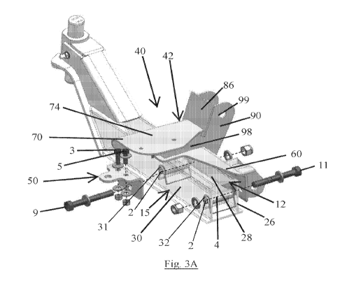
axle bodies and other alternative technologies. Fabricated axle bodies are
typically
manufactured from sheets of steel that are cut, bent and then secured together
by
welding, threaded fasteners or other suitable means. They may have a hollow,
box
like construction having arcuate or rounded corners or transitions between
adjacent
flat surfaces, which result from bending and forming of the sheets of steel
into the
shape desired. Examples of known fabricated axles are shown and described in
International Patent Application Publication No. W02016/196375, and U.S.
Patent
Nos. US8616566, U58544961, U57862058 and U56609764. Variances observed in
dimensional tolerances of these and other components that are manufactured in
this
manner, along with other aspects of their construction that includes their
exterior
shape and reduced weight, generally hollow construction, may present
challenges in
1
CA 03076425 2020-03-17
WO 2019/060836
PCT/US2018/052461
how these components interface with and may be securely attached to other
components in a removable and reversible manner while minimizing vibration and
undesired movement of the components in relation to one another.
[0004] The present disclosure addresses the needs and/or shortcomings of
prior art suspension systems and equipment.
SUMMARY OF THE INVENTION
[0005] There are several aspects of the present subject matter which may be
embodied separately or together in the devices and systems described and
claimed
herein. These aspects may be employed alone or in combination with other
aspects
of the subject matter, and the description of these aspects together is not
intended to
preclude the use of these aspects separately or the claiming of such aspects
separately as set forth in the claims appended hereto.
[0006] In one aspect of this disclosure, an axle seat assembly configured
for
attachment to a vehicle axle comprises a first piece and a second piece. The
first
piece of the axle seat assembly has a first wall and a second wall and a first
axle
seat piece engagement portion that provides a first engagement surface. The
second piece of the axle seat assembly has a third wall and a second axle seat
piece
engagement portion provides a second engagement surface. The first wall and
the
second wall of the first piece are oriented to engage a front surface and a
top surface
of an axle body and the third wall of the second piece is oriented to engage a
rear
surface of an axle body. The first engagement surface of the first piece of
the axle
seat assembly and the second engagement surface of the second piece of the
axle
seat assembly are positioned and configured to engage one another to removably
and reversibly secure with the use of a fastener the first piece to the second
piece
2
CA 03076425 2020-03-17
WO 2019/060836
PCT/US2018/052461
together to form the axle seat assembly
[0007] In a second aspect of this disclosure, an axle seat assembly
attached
to an axle body comprises a first axle seat piece and a second axle seat
piece. The
first axle seat piece has a first wall, a second wall and a first axle seat
piece
engagement portion that provides a first engagement surface. The second axle
seat
piece has a third wall and a second axle seat piece engagement portion that
provides a second engagement surface. An axle body has an exterior surface
that
includes a top surface, a bottom surface, a front surface and a rear surface.
The first
and second engagement surface of the respective first and second axle seat
piece
engagement portions are positioned to engage and be held together by a
fastener.
The first wall of the first axle seat piece is secured to the front surface of
the axle
body and the second wall of the first axle seat piece is secured to the rear
surface of
the axle body by a second fastener.
[0008] In a third aspect of this disclosure, a method of making an axle
seat
assembly having a first piece and a second piece includes providing a first
plate, a
second plate, and a third plate of the first piece of the axle seat assembly.
The first
plate is bent to create a bend line that separates a first section and a
second section
of the first plate and wherein the first section and the second section of the
first plate
are angled in relation to one another after the step of bending the first
plate of the
first piece of the axle seat assembly. The second plate is bent to create a
bend line
that separates a first section and a second section of the second plate. The
first
section and the second section of the second plate are angled in relation to
another
the step of bending the second plate of the first piece of the axle seat
assembly. The
third plate is bent to create a bend line that separates a first section and a
second
section of the third plate. The first section and the second section of the
third plate
3
CA 03076425 2020-03-17
WO 2019/060836
PCT/US2018/052461
are angled in relation to another after the step of bending the third plate of
the first
piece of the axle seat assembly. The first section of the second plate is
secured to
the first plate. The first section of the third plate is secured to the first
plate.
[0009] A first plate of the second piece of the axle seat assembly is also
provided. The first plate of the second piece is bent to create a bend line
that
separates a first and second section of the first plate of the second piece.
The first
and second sections of the first plate of the second piece are angled in
relation to
one another after bending.
[0010] The first axle seat piece is secured to the second axle seat piece
with
the use of a fastener. The first axle seat piece and the second axle seat
piece are
secure to an axle with the use of a second fastener.
BRIEF DESCRIPTION OF THE DRAWINGS
[0011] In describing the preferred examples, reference is made to the
accompanying drawing figures.
[0012] FIG. 1A is left side, upper rear perspective view of a portion of a
lift
axle suspension system incorporating an axle seat assembly according to a
first
embodiment of the present disclosure.
[0013] FIG. 1B is an enlarged right side, upper rear perspective view of a
portion of the subject matter shown in FIG. 1A.
[0014] FIG. 10 is a right side, lower front perspective view of the subject
matter shown in FIG. 1A.
[0015] FIG. 1D is a top view of a portion of the subject matter shown in
FIG.
1A.
[0016] FIG. lE is a bottom view of a portion of the subject matter shown in
FIG. 1A.
4
CA 03076425 2020-03-17
WO 2019/060836
PCT/US2018/052461
[0017] FIG. 2A is a right, rear perspective view of the axle seat assembly
for
the left side of the vehicle axle shown in Figs. 1A-1E, with fasteners that
secure the
axle seat assembly to the vehicle axle and without fasteners that secure a
first piece
of the axle seat assembly to a second piece of the axle seat assembly.
[0018] FIG. 2B is a rear elevational view of the subject matter of FIG.
2A.
[0019] FIG. 20 is a front elevation view of the subject matter of FIG. 2A.
[0020] FIG. 3A is a partially exploded, upper rear perspective, cross
sectional
view of the first embodiment, axle seat assembly configured for mounting to
the left
side of a vehicle axle similar to that shown in FIGS. 1A-1E and 2A-20 with the
cross
section taken perpendicular to the axle on the inboard side of the inboard
axle seat
fastener hole. FIG. 3A shows fasteners that secure the axle seat assembly to
the
vehicle axle and other fasteners that secure a first piece of the axle seat
assembly to
a second piece of the axle seat assembly.
[0021] FIG. 3B is a non-exploded, upper rear perspective, cross sectional
view of the subject matter of FIG. 3A.
[0022] FIG. 4A is right side, upper front perspective view of a first
piece of an
axle seat assembly configured for the left side of a vehicle axle, which is
also shown
in Figures 1A-1E, 2A-20, 3A and 3B.
[0023] FIG. 4B is a left side, upper rear perspective view of the subject
matter
of FIG. 4A.
[0024] FIG. 40 is a rear view of the subject matter of FIG. 4A.
[0025] FIG. 4D is a right side elevational view of the subject matter of
FIG. 4A.
[0026] FIG. 4E is a front elevational view of the subject matter of FIG.
4A.
[0027] FIG. 5A is a plan view of a first plate, in an unbent
configuration, of the
first piece of the axle seat assembly shown in Figure 4A.
CA 03076425 2020-03-17
WO 2019/060836
PCT/US2018/052461
[0028] FIG. 5B is a right side, upper rear perspective view of the first
plate of
FIG. 5A in a bent configuration.
[0029] FIG. 50 is a left side, front upper perspective view of the first
plate of
FIG. 5A in a bent configuration.
[0030] FIG. 5D is a side elevational view of the first plate of FIG. 5A in
a bent
configuration.
[0031] FIG. 6A is a plan view of a first plate, in an unbent
configuration, of a
first piece of an axle seat assembly configured for the left side of a vehicle
axle
according to a further aspect of the present disclosure.
[0032] FIG. 6B is a right side, upper rear perspective view of the first
plate of
FIG. 6A in a bent configuration.
[0033] FIG. 60 is a left side, front upper perspective view of the first
plate of
FIG. 6A in a bent configuration.
[0034] FIG. 6D is a side elevational view of the first plate of FIG. 6A in
a bent
configuration.
[0035] FIG. 7A is a plan view of a second plate, in an unbent
configuration, of
the first piece of the axle seat assembly shown in Figure 4A.
[0036] FIG. 7B is a right side, upper front perspective view of the second
plate
of FIG. 7A in a bent configuration.
[0037] FIG. 70 is right side elevational view of the second plate of FIG.
7A in
a bent configuration.
[0038] FIG. 7D is a bottom plan right side elevational view of the second
plate
of FIG. 7A in a bent configuration.
[0039] FIG. 7E is rear, slight upper perspective view of the second plate
of
FIG. 7A in a bent configuration.
6
CA 03076425 2020-03-17
WO 2019/060836
PCT/US2018/052461
[0040] FIG. 8A is a plan view of a third plate, in an unbent
configuration, of the
first piece of an axle seat assembly shown in FIGURE 4A.
[0041] FIG. 8B is a perspective view of the third plate of FIG. 8A in a
bent
configuration.
[0042] FIG. 9A is a plan view of a plate, in an unbent configuration, that
forms
a part of a bracket for pivotally mounting a lower lift arm to an axle seat
assembly of
the present disclosure.
[0043] FIG. 9B is an elevational view of the plate of FIG. 9A in an unbent
configuration.
[0044] FIG. 90 is a right side perspective view of the plate of FIG. 9A,
in a
bent configuration, to form the right side of a bracket for pivotally mounting
a lower
lift arm to an axle seat assembly of the present disclosure, and which if bent
in the
opposite direction would form the left side of the same bracket.
[0045] FIG. 10A is a plant view of a stabilizing plate of an axle seat
assembly
of the present disclosure.
[0046] FIG. 10B is a side elevational view of the stabilizing plate of
Fig. 10A.
[0047] FIG. 11A is a plan view of a second piece, in an unbent
configuration,
of the axle seat assembly shown in Figures 1A-1E, 2A-20, 3A and 3B.
[0048] FIG. 11B is a perspective view of the second piece shown in FIG.
11A
in a bent configuration.
[0049] FIG. 110 is a front elevational view of the second piece shown in
FIG.
11A in a bent configuration.
[0050] FIG. 11D is a top plan view of the second piece shown in FIG. 11A
in a
bent configuration.
7
CA 03076425 2020-03-17
WO 2019/060836
PCT/US2018/052461
[0051] FIG. 11E is a side elevational view of the second piece shown in
FIG.
11A in a bent configuration.
[0052] FIG. 12A is a plan view of a second piece, in an unbent
configuration,
of an axle seat assembly according to a further aspect of the present
disclosure as
shown in Figure 13E.
[0053] FIG. 12B is a perspective view of the second piece shown in FIG.
12A
in a bent configuration.
[0054] FIG. 120 is a front elevational view of the second piece shown in
FIG.
12A in a bent configuration.
[0055] FIG. 12D is a top plan view of the second piece shown in FIG. 12A
in a
bent configuration.
[0056] FIG. 12E is a side elevational view of the second piece shown in
FIG.
12A in a bent configuration.
[0057] FIGS. 13A-13D shows variations of an axle seat assembly of the
present disclosure mounted to the left side of a vehicle with the inboard end
of the
left side, steering damper arm attached to the second piece of the axle seat
assembly.
[0058] FIG. 14 is a lift axle suspension system incorporating an axle seat
assembly of the present disclosure to which an air spring and steering dampers
are
mounted.
DETAILED DESCRIPTION
[0059] The embodiments disclosed herein are for the purpose of providing a
description of the present subject matter, and it is understood that the
subject matter
may be embodied in various other forms and combinations not shown in detail.
8
CA 03076425 2020-03-17
WO 2019/060836
PCT/US2018/052461
Therefore, specific designs and features disclosed herein are not to be
interpreted as
limiting the subject matter as defined in the accompanying claims.
[0060] As used herein, terms of direction (e.g., front, rear, outboard,
inboard,
vertical, horizontal, lateral, and longitudinal) are to be understood with
reference to
the orientation of the axle (or individual components or portions thereof)
when
associated with a wheeled vehicle, including a trailer, per conventional
design.
[0061] A lift axle suspension system incorporating a first example axle
seat
assembly of the present disclosure is indicated in general at 1. An axle seat,
also
sometimes referred to as an axle chair, is a suspension component that sits on
or
contacts the outer surface of the axle body and provides a further surface or
means
of attaching one end or portion of an energy storing or damping component,
such as
an air spring or a leaf spring to the axle. Another end or portion of the
energy storing
or damping component is typically connected to the vehicle frame, often by way
of a
bracket.
[0062] The lift axle suspension system 1 includes an axle 10 having a
channel
12 and a bottom plate 14, which may be wider than channel 12 to facilitate
fastening
of the bottom plate 14 to the channel 12 by a suitable technique, which may
include
welding. Channel 12 and bottom plate 14 may be made from a variety of suitable
materials, such as for example, high strength steel or other suitable high-
strength
low alloy ("HSLA") steels which may be in sheet form. The left and right side
of Axle
also has respectively, first and second gooseneck sections, at the distal ends
of
which are first and second head sections, each of which includes a king pin to
which
a steering knuckle is mounted. Upper lift arms 18 and lower lift arms 17 are
pivotally
connected both to the axle via the axle seat bracket assembly and to the
vehicle
frame via a bracket assembly that includes a cross channel member.
9
CA 03076425 2020-03-17
WO 2019/060836
PCT/US2018/052461
[0063] The example axle body to which an example axle seat assembly of the
present disclosure is attached is shown in Figures 3A and 3B. The channel 12
of the
example axle body 15 may resemble an upside down, generally U-shaped cross
section that includes a front wall 26, a top wall 28 and a rear wall 30. The
exterior
surface of any one of the front, top, rear and bottom surfaces of the example
axle
body are generally perpendicular to the exterior surface of an adjacent side.
The
exterior surfaces between the front and top walls, and between the top and
rear
walls are round or arcuate as a result of the channel 12 being formed from a
single
sheet of steel and being bent or formed into shape. Front and rear walls 26,30
may
include axle seat fastener holes 31,32 to permit mounting of an axle seat for
suspension components. A torsion resistor and sleeve are inserted between the
front and rear walls in registration with each fastener hole 31,32, as
described and
illustrated in W02016/196375, to strengthen and render the axle body more
resistant
to torsional stresses.
[0064] As used herein, the term "U-shaped" is used broadly and is not
limited
to the illustrated configuration of channel 12 having a pair of downwardly
extending
front and rear walls 26, 30 that are generally perpendicular to a top wall 28.
Other
configurations within the scope of that term may include, for example,
downwardly
extending walls or legs that are inclined with respect to a top wall or curved
to
provide a generally C-shaped cross-section.
[0065] The axle seat assembly of the present disclosure may be used in
combination with a fabricated axle, such as for example, is shown in Figures
3A and
3B, or as described and illustrated in W02016/196375, US8616566, US8544961,
US7862058 and US6609764, each of which are incorporated herein in their
entireties. It will be appreciated, however, that the axle seat assembly of
the present
CA 03076425 2020-03-17
WO 2019/060836
PCT/US2018/052461
disclosure is not limited to use in combination with an axle having a shape or
construction as shown in any of the foregoing cited patent applications or
issued
patents, and may be used in combination with, for example, axles that are
solid or
forged or irregular in shape or that have a cylindrical or partially
cylindrical exterior
surface without departing from the scope of the present disclosure.
[0066] The axle seat assembly 40 of the present disclosure assembly may be
comprised of a first axle seat piece 42 and a second axle seat piece 50.
[0067] The first axle seat piece 42 of the axle seat assembly may include a
first plate 60 (Figs. 5A-5D), a second plate 70 (Figs. 7A-7E), and a third
plate 90
(Figs. 8A-86). The second axle seat piece may include plate 50 (Figs. 11A-
11E). A
portion 69 of the first axle seat piece 42 located at the distal end portion
of the first
plate 60, is positioned and configured to attach the first axle seat piece 42
to the
second axle seat piece 50. A portion 54 of the second axle seat piece 44 is
positioned and configured to attach the second axle seat piece 44 to the first
axle
seat piece 42. In the example axle seat assembly 40, the respective portions
69,54
of the first and second axle seat pieces are positioned and configured to
engage one
another to secure the first axle seat piece 42 and second axle seat piece 44
together. Each of the foregoing elements or features will now be discussed in
further
detail.
[0068] Turning to Figures 5A-5E, the first plate 60 of the first axle seat
piece
42 serves as a support for the first axle seat piece 42, as shown in Figs. 4A-
4E, and
includes a first section or first wall 62 and a second section or second wall
64 with
the two sections or walls separated by a bend line 63. The first section 62
and
second section 64 of the example first plate 60 are positioned flush with,
respectively, the rear surface or rear wall 30, and the top surface or top
wall 28 of the
11
CA 03076425 2020-03-17
WO 2019/060836
PCT/US2018/052461
axle body 15. In the first example axle seat assembly 40, the first plate 60
preferably
contacts only two of the four sides or surfaces of the axle body 15 with the
first
section 62 contacting the rear surface 30 and the second section 64 containing
the
top surface 28.
[0069] The first plate 60 is preferably removably and reversibly secured to
the
axle body 15 by a suitable fastener arrangement (Figures 3A-36). In this
example,
the first section 62 of the first plate 60 defines a first or outboard bore 65
and a
second or inboard bore 66 (Fig. 4E). When placed in position for attachment to
the
axle body, each of the first and second bores 65,66 of the first plate 60 are
aligned
with axle seat fastener holes 31,32 defined in each of the rear wall 30 and
the front
wall 26 of the axle body. Fastener 9,11 are received in the outboard bore and
the
inboard bore of the first section of the first plate to secure the axle body.
[0070] The portion 69 of the first axle seat piece 42 that is positioned
and
configured for engagement with the second axle seat piece 44 to provide a
means
for removably and reversibly attaching the first and second axle seat pieces
42,44
together is positioned at the distal end portion of the first plate 60 of the
first axle
seat piece 42 and forward of the front wall 26 of the axle body 15 (Figs.
3A,36).
This portion 69 of the first axle seat piece 42, which may also be referred to
as the
axle seat piece engagement portion 69 of the first axle seat piece 42,
includes an
engagement surface and first and second bores 67,68 and will be discussed
further
below.
[0071] The second axle seat piece 50 of the axle seat assembly 40 may
include a plate having a first section or first wall 52 and a second section
or second
wall 54 with the two sections separated by a bend line 53 (Figs. 11A-11 E).
The first
section 52 of the second axle seat piece 50 defines a wall that is positioned
for
12
CA 03076425 2020-03-17
WO 2019/060836
PCT/US2018/052461
engagement with the front wall or front surface 26 of the axle body 15 (Figs.
3A,36).
The first section 52 of the second axle seat piece 50 also defines a bore 51
that may
be aligned with the outboard bore 65 in the first section 62 of the first axle
seat piece
42. The same fastener 9 received in aligned bores 51 (second piece),31 (axle
body), 65 (first wall of first plate) removably and reversibly secures the
second axle
seat piece 50 to the front surface or front wall 26 of the axle body. When
fastener 11
received within the inboard bore 66 of the first section 62 of the first plate
60, and
fastener 9 are tightened, the first and second axle seat pieces 42,50 are
secured to
the axle body 15 and the axle body is placed in compression. The axle body
interfacing with two separate axle seat pieces rather than only an integrally
formed
single piece permits the axle seat assembly to be tightly fit to a number of
different
axle body types and to accommodate effectively and at a reduced cost, the
anticipated and unanticipated variations in the precise dimensions of an axle
body
depending on how it is designed and manufactured. While the first piece and/or
second piece of the axle seat assembly could be welded to the axle body if
desired,
when the first piece, the second piece or both are reversibly and removably
secured
to the axle body, this excludes that piece or pieces being welded to the axle
body.
[0072] The second section 54 of the second axle seat piece 50 (Figs. 11B)
defines a generally horizontally disposed wall that provides the portion of
the second
axle seat piece 50 that is positioned and configured for engagement with the
first
piece 42 of the axle seat assembly 40. This portion of the second axle seat
piece
50, which may also be referred to as the axle seat piece engagement portion of
the
second axle seat piece 50, includes an engagement surface and first and second
bores 55,56 that correspond with the engagement surface and first and second
bores 67,68 of the axle seat piece engagement portion 69 of the first axle
seat piece
13
CA 03076425 2020-03-17
WO 2019/060836
PCT/US2018/052461
42. When the respective engagement surfaces are bought into contact with one
another and fasteners 3,5 received within respective bores are tightened, the
first
axle seat piece 42 and the second axle seat piece 50 are reversibly and
removably
secured to one another. The first axle seat piece 42 and the second axle seat
piece
50 may be secured together before or after their attachment to the axle body.
While
the first piece and the second piece of the axle seat assembly could be welded
together if desired, when the first and second pieces are reversibly and
removably
secured together, this excludes their being welded to one another.
[0073] As shown in Fig.15, the second axle seat piece 50 may optionally
include a vertical bore 59 (FIG. 11B) in the second section or second wall 54
for
mounting the inboard end of a steering damper 99.
[0074] As shown in Figures 7A-7B, the second plate 70 of the first axle
seat
piece 42 may be considered to include a first section 72 and a second section
74,
with the two sections 72 and 74 separated by a bend line 73. The first section
72 of
the second plate 70 defines a vertically oriented ear 78 configured to be
positioned
on the first section 62 of the first plate 60 and a frame member or leg 77
configured
to extend away from the ear 78 and across the second section 64 of the first
plate
60. The lower interior edge 71 of the ear 78 may be configured to be supported
by
the first section 62 of the first plate 60, while the lower edge 75 of the
frame member
77 may be configured to be supported upon the upper surface or top surface of
the
second section 64 of the first plate 60. In the illustrated embodiment, the
ear 78 is
provided with a hole or opening 79 positioned above the top surface 28 and
forward
of the front surface 26 of the axle body 15 and is configured for connecting
the axle
seat assembly 40 to an upper pivoting arm 18 of an axle lift assembly.
14
CA 03076425 2020-03-17
WO 2019/060836
PCT/US2018/052461
[0075] The second section 74 of the second plate 70 provides, when bent
generally perpendicular to the first section 72, a platform or horizontally
disposed
wall to which the lower end of an air spring 19 or the like may be secured
(Fig. 7B).
The frame member 77 of the first section 72 elevates the second section 74
above
the second section 64 of the first plate 60, as shown in Figures. 2B and 40.
[0076] Turning to Figures 8A-8B, the third plate 90 may be considered to
include a first section 92 and a second section 94, with the two sections 92
and 94
separated by bend line 93. In a manner that is generally similar to first
section 72 of
the second plate 70, the first section 92 of the third plate 90 defines a
vertically
oriented ear 96 configured to be positioned on the first section 62 of the
first plate 60
and a frame member or leg 98 configured to extend away from the ear 96 and
across the top surface of the second section 64 of the first plate 60 (Fig.
4A). The
second section 94 of the third plate 90 is angled in relation to the first
section 92 and
provides an additional support for the platform defined by the second section
74 of
the second plate 70 (Fig. 40).
[0077] The lower pivoting arm 17 of the axle lift assembly can be secured
to
the axle seat assembly 40 by way of bracket 85 secured on the exterior surface
of
the first wall of the first plate 60 in board of the second and third plates
(Figs. 4A-46).
Bracket 80 is formed from a pair of spaced apart, ear shaped plates 80 having
a first
section 82 and a second section 84, the two sections separated by a bend line
83
(Figs. 9A-90). The first section 82 includes a bore for receiving one end
portion of
the pin of the pivot bushing of the lower lift arm. The second section 84 of
the left
side plate 80 is bent to the right. The second section of the right side plate
80 is bent
to the left. The two plates together form the bracket 85 which is secured to
the first
section 62 of the first plate 60 of the axle seat assembly 40. The lower lift
arm 17 is
CA 03076425 2020-03-17
WO 2019/060836
PCT/US2018/052461
pivotally mounted to the bracket 85 by receipt of the central pin of the lower
lift arm
pivot bushing in mounting holes 81. The upper lift arm 18 is pivotally mounted
to the
axle seat assembly 40 by receipt of the central pin of the upper lift arm in
mounting
holes 79,99 positioned above and in front of the axle body in the ears 78, 96
of the
second and third plates 70,90. As shown in Figures 1A, 10 and 1F, the lower
lift arm
pivotally attaches to the axle seat bracket assembly inboard of the location
of pivotal
attachment of the upper lift arm. The opposing ends of the lower lift and
upper lift
arm are laterally aligned and vertically offset at the locations of their
pivotal
attachment to a bracket assembly which in turn is connected to the vehicle
frame.
[0078] With the second and third plates 70 and 90 in their bent
configurations,
the second and third plates 70 and 90 may be arranged with the first sections
72 and
92 generally parallel to each other and spaced an appropriate distance apart
as
shown in FIG. 20. The second section 74 of the second plate 70 which forms a
platform or horizontally disposed wall may be arranged so as to extend toward
the
third plate 90, with the second section 94 of the third plate 90 extending
away from
the first section 72 of the second plate 70. The second section 94 of the
third plate
90 may be secured to the underside of the second section 74 of the second
plate 70.
A stabilizing plate 86 (Fig. 1) may be attached to the ears 79,99 to provide
additional
stability, strength, and rigidity to the axle seat assembly 40, if desired.
[0079] The first sections 72 and 92 of the second and third plates 70 and
90
may be secured to the top surface of the first plate 60 by any suitable,
permanent or
reversible, fastener arrangement (e.g., welding or mechanical fasters). For
example,
the axle seat assembly may be welded at the edges of the interface between the
first, second and third plates and the stabilizing plate 86 (e.g., between the
top
surface of the first plate 60 and the lower edge of the frame members 77, 98
and the
16
CA 03076425 2020-03-17
WO 2019/060836
PCT/US2018/052461
lower interior edge of the ears 71,91, between the top edge of the frame
member 98
of the third plate 90 and the bottom surface of the platform 74, and between
the
stabilizing plate 86 and the first, second and third plates 60, 70, 90. The
axle seat 15
may then be connected to other vehicle components, such as the ears 78 and 96
being connected to pivoting arms of an axle lift assembly and the second
section 74
of the second plate 70 being connected to an air spring 19 or the like.
It will be appreciated the axle seat assembly can be variously configured
without departing from the scope of the present disclosure.
For example, as shown in Figs 12B and 13B-13D, the first section or first wall
152 of the second piece 150 of the axle seat assembly may include more than
one
bore each of which is aligned with a corresponding bore in the first section
of the first
plate and intervening bores in the front wall and rear wall of the axle body.
The respective axle seat piece engagement portions 69, 54 of the first and
second axle seat pieces 60, 50 by which the first and second axle seat pieces
are
removably and reversibly secured to one another may also be varied,
independently
or in coordination with one another to achieve any one of a number of
objectives,
including but not limited to providing an inboad side, point of attachment of
the
steering damper to the second axle seat piece at a controlled distance from
end of
the axle (which may be held constant if desired) despite variations in the
size or the
length of the axle or the location of bores 30 or 31 (see Fig. 3B vs. 13A vs.
13B-
13D).
17