Note: Descriptions are shown in the official language in which they were submitted.
CA 03076531 2020-03-19
WO 2019/195200 PCMJS2019/025252
KINETIC SHEAR RAM FOR WELL PRESSURE CONTROL APPARATUS
Background
[0001] This disclosure relates to the field of well pressure control
apparatus, namely,
blowout preventers (BOPs). More specifically, the disclosure relates to
actuating rams
for so called "shear rams" which are used to close a BOP when there are tools,
pipe or
other devices in a subsurface well that prevent ordinary operation of other
devices used to
close a BOP
[0002] Blowout preventers (BOPs) used with, e.g., oil and gas wells, are
provided to
reduce risk of potentially catastrophic events known as a blowouts, where high
well
pressures and resulting uncontrolled flow from a subsurface formation into the
well can
expel tubular products (e.g., drill pipe and well casing), tools and fluid out
of a well.
Blowouts present a serious safety hazard to drilling crews, drilling rigs and
the
environment and can be extremely costly to control, repair and remediate
resulting
damage. Typically BOPs have "rams" that opened and closed by actuators. The
most
common type of actuator is operated hydraulically to push closure elements
across a
through bore in a BOP housing (itself sealingly coupled to the well) to close
the well. In
some types of BOPs the rams have hardened steel shears to cut through a drill
string or
other tool or device which may be in the well at the time it is necessary to
close the BOP.
[0003] A limitation of many hydraulically actuated rams is that they
require a large
amount of hydraulic force to move the rams against the pressure inside the
wellbore and
in the case of shear rams subsequently to cut through objects in the through
bore.
[0004] An additional limitation of hydraulically actuated rams is that the
hydraulic force
is usually generated at a location away from the BOP (necessitating a
hydraulic line from
the pressure source to the rams), making the BOP susceptible to failure to
close if the
hydraulic line conveying the hydraulic force is damaged. Further limitations
associated
with hydraulically actuated rams may include erosion of cutting and sealing
surfaces due
to the relatively slow closing action of the rams in a flowing wellbore.
Cutting through
1
CA 03076531 2020-03-19
tool joints, drill collars, large diameter tubulars and off center pipe
strings under heavy
compression may also present problems for hydraulically actuated rams.
[0005] A further limitation associated with hydraulically actuated shear
ram BOPs
is that the cutting blades are asymmetrical which leads to a splitting force
being
generated during the shearing action.
[0006] Pyrotechnically actuated BOPs have been proposed which address many
of the
limitations of hydraulic BOPs, such BOPs including those described in
International
Application Publication No. WO 2016/176725 to Kinetic Pressure Control
Limited. A
limitation of pyrotechnic based BOPs such as disclosed in the foregoing
publication is
that the shearing element must cut through an isolation ring before it is
possible to shear
devices located in the through bore. The isolation ring is made as a heavy,
thick element
to exclude entry of well fluid under pressure into the pyrotechnic charge and
shear
storage volume at wellbore pressure. Thus, the presence of an isolation ring
can
significantly increase required shearing energy to ensure proper function of
the shear
ram(s). Further, the isolation ring may generate additional debris upon
shearing which
may damage sealing arrangements within the BOP.
Summary
[0006.1] In accordance with an aspect of at least one embodiment, there is
provided
a blowout preventer comprising: a main body having a through bore; a passage
transverse
to the through bore; a ring cutter disposed in the passage and configured for
positioning
with an opening on the cutter coincident with the through bore; a gate
disposed separated
and spaced apart from the ring cutter and configured for motion along the
passage; and a
charge configured for activation to propel the gate along the passage into
contact with the
ring cutter to move the cutter across the through bore.
[0006.2] In accordance with an aspect of at least one embodiment, there is
provided
a blowout preventer comprising: a main body having a through bore; a passage
transverse
to the through bore; a ring cutter disposed in the passage and configured for
positioning
2
CA 03076531 2020-03-19
with an opening on the cutter coincident with the through bore; and a gate
configured for
motion along the passage in response to activation of a charge, wherein the
gate is
configured to move along the passage between a position separated and spaced
apart
from the ring cutter to a position where the gate contacts the ring cutter to
move the cutter
across the through bore.
[0006.3] In accordance with an aspect of at least one embodiment, there is
provided
a method of operating a blowout preventer having a body with a through bore,
comprising: actuating a charge to propel a gate along a passage in the body
transverse to
the through bore, wherein the gate is propelled from a position separated and
spaced apart
from a ring cutter disposed in the passage with an opening on the cutter
coincident with
the through bore, to a position where the gate contacts the ring cutter; and
allowing the
propelled gate to move the ring cutter across the through bore.
[0007] A blowout preventer according to one aspect of the present
disclosure has a main
body having a through bore. A housing is mounted to the main body and defines
a
passage connected to and transverse to the through bore. An isolation ring
cutter is
initially disposed around the through bore and closes the passage to fluid
flow. The
isolation ring cutter is movable along the passage and has an opening
coincident with the
through bore. A piston and gate are disposed in the passage spaced apart from
the
isolation ring cutter. A propellant charge is disposed between the piston and
an end.
100081 In some embodiments the blowout preventer further comprises an
energy
absorbing element disposed in the housing proximate the main body.
2a
CA 03076531 2020-03-19
WO 2019/195200 PCT/US2019/025252
[0009] In some embodiments the blowout preventer further comprises a
restraint in the
housing arranged to stop motion of the piston and the gate until gas pressure
from the
propellant charge reaches a selected threshold.
[0010] In some embodiments, the restraint comprises a shear pin.
[0011] In some embodiments, the isolation ring cutter comprises a cutting
edge formed
into a circumference of the opening.
[0012] In some embodiments, the blowout preventer further comprises a seal
disposed in
the main body and coaxial with the through bore, the seal arranged to close
the through
bore to fluid flow when the gate is moved to a position laterally adjacent to
the seal.
[0013] In some embodiments, the pre-initiation spacing between the gate and
isolation
ring cutter may be between 1/8 to lA of the diameter of the through bore, or
may be
greater than 1/2 the diameter of the through bore.
[0014] In some embodiments, a mass of the isolation ring cutter is less
than 20 percent of
the combined mass of the piston and the gate.
[0015] In some embodiments, a mass of the isolation ring cutter is less
than 10 percent of
the combined mass of the piston and the gate.
[0016] In some embodiments, the isolation ring cutter comprises at least
one of steel and
ceramic.
[0017] In some embodiments, the ceramic comprises metal carbide.
[0018] A method for closing a well according to another aspect of the
disclosure includes
actuating a propellant charge disposed in a blowout preventer having a main
body
coupled to the well and including a through bore, a housing mounted to the
main body,
the housing defining a passage connected to and transverse to the through
bore, an
isolation ring cutter initially disposed around the through bore and closing
the passage to
fluid flow, the isolation ring cutter movable along the passage and having an
opening
coincident with the through bore, a piston and gate disposed in a pressure
chamber
spaced apart from the isolation ring cutter wherein the propellant charge is
disposed
3
CA 03076531 2020-03-19
WO 2019/195200 PCT/US2019/025252
between the piston and an end. Gas pressure from the actuated propellant
charge moves
the piston, the gate and the isolating ring cutter into the through bore
cutting a device
disposed in the through bore. The passage is thus sealed against fluid
communication
from the through bore.
[0019] Some embodiments further comprise slowing the piston by contacting
an energy
absorbing element disposed in the housing proximate the main body.
[0020] Some embodiments further comprise restraining motion of the piston
and the gate
until gas pressure from the propellant charge reaches a selected threshold.
[0021] In some embodiments, the selected threshold is set by selecting
properties of a
shear pin.
[0022] In some embodiments the isolation ring cutter comprises a cutting
edge formed
into a circumference of the opening.
[0023] In some embodiments, a mass of the isolation ring cutter is less
than 20 percent of
the combined mass of the piston and the gate.
[0024] In some embodiments, a mass of the isolation ring cutter is less
than 10 percent of
the combined mass of the piston and the gate.
[0025] In some embodiments, the isolation ring cutter comprises at least
one of steel and
ceramic.
[0026] In some embodiments, the ceramic comprises metal carbide.
Brief Description of the Drawings
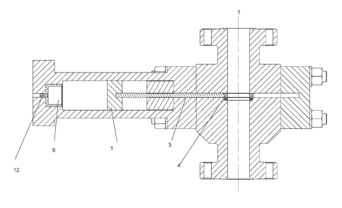
[0027] FIG. 1 shows a section view of an example embodiment of a BOP
according to
the present disclosure.
[0028] FIG. 2 shows a plan view of the BOP of FIG. 1.
[0029] FIG. 3 shows the section view of FIG. 1 prior to initiation of a
charge.
[0030] FIG. 4 shows initiation of operation of a shear element when gas
pressure from
the charge exceeds a selected threshold.
4
CA 03076531 2020-03-19
WO 2019/195200 PCT/US2019/025252
[0031] FIG. 5 shows a crush core at the beginning of crush to slow a
kinetic energy gate.
[0032] FIG. 6 shows position of the kinetic energy gate at the end of the
crush.
Detailed Description
[0033] With reference to FIG. 1, there is shown a sectioned elevational
view of an
example embodiment of a blowout preventer 100 (BOP) according the present
disclosure.
The blowout preventer 100 has a main body 5 having a through bore 7. The
blowout
preventer 100 also has a passage 8 that is oriented transversely to the
through bore 7. An
isolation ring cutter 4 fluidly seals the passage 8, which extends from the
through bore 7
into a pressure housing 10. The isolation ring cutter 4 is positioned inside
the main body
and has an opening (see FIG. 2, element 4A) centered about the through bore 7
prior to
actuation of the BOP 100. See FIG. 2 for a plan view. A cutting edge (see 4A
in FIG. 2)
may be formed on the circumference of the opening in the isolation ring cutter
4. A
piston 1 and a gate 3 are disposed in the pressure housing 10. The gate 3 may
be a flat
plate, e.g., as may be made from steel, shaped to enable longitudinal motion
along the
passage 8 and to act in the same manner as a gate in a gate valve to close the
through bore
7 as will be further explained. A charge 9, which may be in the form of a heat
and/or
percussively initiated chemical propellant, is located between the piston 1
and an end cap
11 at the longitudinal end of the pressure housing 10 opposite the main body
5. The
charge 9 may be initiated and combust or react to produce high pressure gases,
which in
turn propel the piston 1 and thus the gate 3 through the pressure housing 10
and into the
isolation ring cutter 4. Kinetic energy from the piston 1 and the gate 3 are
transferred to
the isolation ring cutter 4 to propel the isolation ring cutter 4 along the
passage 8 and
across the through bore 7. In addition, the gate 3 and isolation ring cutter 4
may remain
in intimate contact as they travel across the through bore 7 allowing the
force from the
expanding gases to continue to act through the piston 1 and gate 3 and onto
the isolation
ring cutter 4 during shearing to increase shearing effectiveness as will be
described in
greater detail below.
5
CA 03076531 2020-03-19
WO 2019/195200 PCT/US2019/025252
[0034] In some embodiments, the pre-initiation spacing between the gate 3
and isolation
ring cutter 4 may be between 1/8 to 1/2 of the diameter of the through bore 7,
or may be
greater than 1//2 the diameter of the through bore 7.
[0035] An arresting mechanism in the form of an energy absorbing element 2
is located
inside the pressure housing 10 between the piston 1 and a bonnet 6. The energy
absorbing
element 2, which may be made from a crushable material, is adapted to absorb
the kinetic
energy of the piston 1 and the gate 3, as will be described in greater detail
below.
[0036] The operation of the blowout preventer 100 will now be explained
with reference
to FIG 2, which a cross section view of the blowout preventer 100 prior to
being
activated. As can be observed in FIG. 2, the charge 9, piston 1 and gate 3 are
located on a
first side of the through bore 7; the center line of the through bore 7 may be
observed at
CL.
[0037] FIG. 2 also shows an initiator 12 which is adapted to activate the
charge 9. FIG. 2
also shows the isolation ring cutter 4 fluidly sealing the passage 8 from the
through bore
7. Around the through bore 7 a through bore seal 13 may be disposed below the
lower
plane of the gate 3, which will be explained in more detail below.
[0038] The energy absorbing element 2 may be located within the passage 8
on the same
side of the through bore 7 as the piston 1 and gate 3
[0039] FIG. 3 shows a cross section view of the blowout preventer 100 where
the charge
9 has not yet been activated by the initiator 12. The piston 1 and gate 3 are
held in place
against the forthcoming force of gas pressure from the charge 9 acting on the
piston 1 by
a restraint, for example a shear pin (not shown), until sufficient pressure
from gases from
the charge 9 has occurred after activation of the charge 9, that is, when
pressure reaches a
selected threshold. The restraint, if only a single shear pin or similar
device, may hold
either the piston 1 or the gate 3.
[0040] FIG. 4 shows a cross section view of the blowout preventer 100 where
a sufficient
expansion of hot gases has occurred after activation of the charge 9 to break
the shear pin
(not shown). At this stage, the piston 1 and gate3 are accelerating along the
passage 8
6
CA 03076531 2020-03-19
WO 2019/195200 PCT/US2019/025252
toward the isolation ring cutter 4 and the through bore 7. Once contact is
made between
the gate 3 and the isolation ring cutter 4, kinetic energy is transferred from
the piston 1
and gate 3 to the isolation ring cutter 4, thereby propelling the isolation
ring cutter 4 into
the through bore 7. The gate 3 may remain in intimate contact with the
isolation ring
cutter 4 as it traverses the through bore 7, thereby adding to the force the
isolation ring
cutter 4 is able to impart during shearing. Expanding gases behind the piston
1 may
continue to act on the piston 1 during shearing as the isolation ring cutter 4
traverses the
through bore 7. Thus additional force is provided beyond that produced by
kinetic energy
from the piston 1 and gate 3. The isolation ring cutter 4 will shear any
wellbore tubulars,
tools or other objects which are present in the through bore 7.
[0041] Materials for the isolation ring cutter 4 may include strong and
hard materials
such as high strength steel and certain ceramics, such as metal carbides, e.g.
tungsten
carbide. Ceramics may be used for the entire structure of the isolation ring
cutter 4 or
may be applied as a coating to a high strength material, e.g., steel,
substrate.
[0042] In some embodiments, the mating faces between the isolation ring
cutter 4 and the
gate 3 may be shaped to provide even loading. FIG. 4 shows that the geometry
of the
isolation ring cutter 4 (a flat face) and the corresponding geometry on the
gate 3 (also a
flat face) are complimentary, thus reducing point loading and allowing for
more even
stress distribution. It would also be possible to provide curved surfaces
having similar
radii on both the isolation ring cutter 4 and the gate 3 or a combination of
flat surfaces
and similar radius curved surfaces (not shown).
[0043] FIG. 4 shows that in the present embodiment the isolation ring
cutter 4 is much
smaller in size than the gate 4 and the piston 1. This may be advantageous in
reducing
shock loading when the travelling assembly (the gate 4 and the piston 1)
impacts the
isolation ring cutter 4. In some embodiments, the isolation ring cutter 4 has
mass less
than 20% of the mass of the (travelling assembly) piston 1 and gate 3 in
combination. In
some embodiments, the mass of the isolation ring cutter 4 it is less than 10%
of the
travelling assembly mass.
7
CA 03076531 2020-03-19
WO 2019/195200 PCT/US2019/025252
[0044] FIG. 5 shows a cross section view of the blowout preventer 100. At
this stage, the
isolation ring cutter 4 has sheared through anything that may have been
located in the
through bore 7. The front face of the piston 1 has now begun to contact the
energy
absorbing element 2, at such point in its minimum crush state. The isolation
ring cutter 4
has now begun to contact the energy absorbent material (not shown separately)
of the
energy absorbing element 2 located in the passage in front of the isolation
ring cutter 4.
[0045] FIG. 6 shows a cross section view of the blowout preventer 100 where
the body of
energy absorbing material of the energy absorbing element 2 has crumpled to a
predetermined amount, absorbing the kinetic energy of the piston 1 and the
gate 3. The
energy absorbent material (not shown separately) located in the passage 8 has
also
crumpled to a predetermined amount, absorbing the kinetic energy of the
isolation ring
cutter 4.
[0046] The energy absorbing element 2 will retain the gate 3 in such a
position that a
sealing face (not shown) on the gate 3 is substantially aligned with the seal
13. When
such alignment occurs, the seal 1 will laterally press against the sealing
face (not shown)
on the gate 3, to stop the flow of well fluids through the through bore 7,
thereby securely
closing the well.
[0047] Once the well is securely closed, well fluid pressure control
operations (for
example choke and kill operations) can commence. Once well fluid pressure
control has
been re-established, the blowout preventer 100 can be reopened, such as by
retracting the
gate 3 to open the through bore 7. For example, hydraulic fluid 15 may be
introduced
between the front face of the piston 1 and the bonnet 6 to cause the piston 1
to retract
away from the through bore 7.
[0048] The gate 3 may optionally have a sealing face (not shown separately)
which is
adapted to engage with the through bore seal 13 to prevent passage of wellbore
fluids
from the through bore 7 into the passage 8. A sealing face (not shown) may
optionally be
present on at least one of a lower or upper surface portion of the gate 3. In
an example
embodiment, the sealing face (not shown) may be provided on at least a lower
surface
portion of the gate 3.
8
CA 03076531 2020-03-19
WO 2019/195200 PCT/US2019/025252
[0049] A possible advantage of a BOP made according to the present
disclosure is that
the blow out preventer can be actuated without having to produce hydraulic
forces to
hydraulically push rams across the through bore to close off the through bore.
Instead, the
energy required to close the wellbore is contained in the charge in the
blowout preventer
where it is required.
[0050] A possible advantage of holding the piston 1 and gate 3 in place by
a shear pin is
that this assists in the rapid acceleration of the piston 1 and gate 3 along
the passage 8
once sufficient force has been generated by the expanding gases of the charge
9.
[0051] A possible advantage of having the isolation ring cutter 4 fluidly
sealing the
passage 8 from the through bore 7 is that the piston 1 and gate 3 can
accelerate along the
passage 8 unhindered by well fluids or other liquids until the piston 1 and
gate 3 contact
the isolation ring cutter 4.
[0052] A possible advantage of using an energy absorbing element 2 is that
excess
kinetic energy of the gate and piston is not directly transferred into a
structural portion of
the blowout preventer 100.
[0053] A possible advantage of using an isolation ring cutter 4 in
connection with the
piston 1 and the gate 3 is that a separate isolation ring does not need to be
sheared in
addition to items that may be located in the through bore. An additional
possible benefit
is that there is no debris from shearing a separate isolation ring that may
negatively
impact seal performance.
[0054] Although only a few examples have been described in detail above,
those skilled
in the art will readily appreciate that many modifications are possible in the
examples.
Accordingly, all such modifications are intended to be included within the
scope of this
disclosure as defined in the following claims.
9