Note: Descriptions are shown in the official language in which they were submitted.
1
APPARATUSES AND METHODS FOR DRYING HAY BALES
FIELD OF THE INVENTION
The present invention relates generally to agriculture, and more
particularly to equipment and techniques for drying baled hay.
BACKGROUND
In the field of agriculture, it has been previously proposed to construct
equipment capable of drying hay bales in the interest of overcoming problems
with the
more conventional approach leaving cut hay in the field to dry before baling.
Examples of such prior bale drying equipment can be seen in Published US
Patent
Applications US20180306503 and US20190024973.
The former reference discloses a hay bale dryer in which a rack of
spikes is movably carried atop a platform on which a hay bale is seated. The
rack is
lowered into a working position driving the spikes downwardly into the bale,
and
forced air is supplied through the hollow spikes, and permeates into the bale
through
slots or holes in the spikes. Hydraulic cylinders linearly displace the spike
rack
between its lowered working position penetrating the bale, and its raised non-
working
position withdrawn from the bale.
The latter reference similarly uses hollow needles to distribute drying air
into the bale, but employs two sets of such needles carried on respective air
manifolds disposed above and below a bale holding space in order to penetrate
a
group of bales from both the topside and underside thereof. Hydraulic
cylinders are
used to linearly displace the two manifolds toward and away from one another
between the bale-penetrating working position and the retracted non-working
position
withdrawn from the bale. In addition to the hydraulic the cylinders, a system
of tracks,
gears, chains and driveshafts is used to balance the air manifolds during the
cylinder-
CA 3076779 2020-03-24
2
powered displacement thereof.
Despite these prior innovations in the art, there remains room for
improvements and alternatives in hay drying equipment, and associated
equipment
for loading and unloading bales to and from such dryers.
SUMMARY OF THE INVENTION
According to a first aspect of the invention, there is provided a bale
drying apparatus comprising:
a support frame;
a bale space delimited within said support frame and sized to receive at
least one hay bale within said bale space;
an air manifold movably coupled to the support frame and connected or
connectable to an air source from which air is supplied to said manifold;
a plurality of spears each attached to the air manifold, each comprising
a hollow interior fluidly connected to an interior space of the air manifold
therewith to
receive the supplied air therefrom, and each comprising a plurality of
apertures
therein through which the supplied air can exit the hollow interior of the
spear;
wherein:
the air manifold is movable between a deployed position in which
the plurality of spears penetrate into the bale space, and a retracted
position in which
the plurality of spears are retracted out of said bale space; and
each spear, at locations within a longitudinal span of the hollow
interior of said spear, includes a plurality of locations possessing different
respective
cross-sectional sizes in respective cross-sectional planes lying normal to
said
longitudinal span, and said different respective cross-sectional sizes, in at
least a first
dimension measured transversely of said longitudinal span, grow sequentially
CA 3076779 2020-03-24
3
narrower toward a distal end of the spear situated furthest from the air
manifold.
According to a second aspect of the invention, there is provided an
aeration spear for a bale dryer, said aeration sphere comprising a hollow
elongated
body connected or connectable to an air manifold of the bale dryer in a
position fluidly
communicating a hollow interior of the hollow elongated body with the air
manifold to
receive supplied air therefrom, and a plurality of apertures in said hollow
elongated
body through which the supplied air can exit the hollow interior thereof,
wherein,
within a longitudinal span of the hollow interior, said hollow elongated body
includes a
plurality of locations possessing different respective cross-sectional sizes
in
respective cross-sectional planes lying normal to said longitudinal span, and
said
different respective cross-sectional sizes, in at least a first dimension
measured
transversely of said longitudinal span, grow sequentially narrower toward a
distal end
of the hollow elongated body.
According to a third aspect of the invention, there is provided a method
of manufacturing an aeration spear for a bale dryer, said method comprising:
(a) obtaining a pipe having a hollow interior; and
(b) at least at a terminal end of an originally cylindrical portion of said
pipe, deforming said originally cylindrical portion of said pipe into non-
cylindrical form
by forcibly squeezing together opposing sides of said originally cylindrical
portion to
reduce a cross-sectional size of said originally cylindrical portion in a
dimension in
which said opposing sides are opposed, thereby creating a narrowed piercing
end of
said aeration spear at said terminal end of the originally cylindrical portion
of said
pipe.
According to a fourth aspect of the invention, there is provided a bale
drying apparatus comprising:
CA 3076779 2020-03-24
4
a support frame;
a bale space delimited within said support frame and sized to receive at
least one hay bale within said bale space;
an air manifold movably coupled to the support frame and connected or
connectable to an air source from which air is supplied to said manifold;
a plurality of spears each attached to the air manifold, each comprising
a hollow interior fluidly connected to an interior space of the air manifold
therewith to
receive the supplied air therefrom, and each comprising a plurality of
apertures
therein through which the supplied air can exit the hollow interior of the
spear;
wherein
the air manifold is movable between a deployed position in which
the plurality of spears penetrate into the bale space, and a retracted
position in which
the plurality of spears are retracted out of said bale space;
the air manifold is movably carried on the support frame by at
.. least one crank arm pivotably coupled to the support frame; and
at least one actuator is connected between the support frame and
said at least one crank arm and operable to pivot said at least one crank arm
in both a
deployment direction moving the air manifold toward the deployed position and
a
retraction direction moving the air manifold toward the retracted position.
According to a fifth aspect of the invention, there is provided a bale
feeding apparatus for feeding bales into a bale dryer, said apparatus
comprising:
a structure defining an elongated lane having a proximal end for residing
adjacent the bale dryer and a distal end for residing opposite of the bale
dryer, said
lane having a sufficient length to support a plurality of bales thereon in
queued fashion
in a plurality of queuing spots residing between said proximal end distal
ends;
CA 3076779 2020-03-24
5
a bale mover in co-operably installed relation to said structure and
configured to advance the plurality of bales sequentially through the
plurality of
queuing spots toward the proximal end of the lane and into the bale dryer from
said
proximal end of the lane; and
at least one actuator connected to the bale mover and operable to
displace the bale mover longitudinally back and forth of the structure in an
advancing
direction toward the proximal end of the lane and a retreating direction back
toward
the distal end;
wherein the bale mover comprises one or more bale engagement units
movable between a working position protruding into the lane to displace the
plurality
of bales during movement in the advancing direction, and a reset position
withdrawn
from the lane bypass the plurality bales during movement in the retreating
direction.
BRIEF DESCRIPTION OF THE DRAWINGS
Preferred embodiments of the invention will now be described in
conjunction with the accompanying drawings in which:
Figure 1 is a rear perspective view of a bale dryer of a first embodiment
of the present invention, showing the bale dryer in a closed state operable to
dry hay
bales previously received in the dryer in an open state thereof.
Figure 2 is an overhead plan view of the bale dryer of Figure 1.
Figure 3 is a rear elevational view of the bale dryer of Figure 1.
Figure 4 is a side elevational view of the bale dryer of Figure 1.
Figure 5 is a cross-sectional view of the bale dryer of Figure 3, as
viewed along line C ¨ C thereof.
Figure 6 is a side elevational view of the bale dryer of Figure 1, but in
the open state ready to accept and release hay bales thereto and therefrom.
CA 3076779 2020-03-24
6
Figure 7 is a rear elevational view of the bale dryer of Figure 6.
Figure 8 is a cross-sectional view of the bale dryer of Figure 7, as
viewed along line D ¨ D thereof.
Figure 9 is a perspective view of an aeration spear from the bale dryer
of Figure 1, with associated mounting components shown in exploded relation to
the
spear.
Figure 10 is an end view of the aeration spear of Figure 9 from a distal
penetrating end thereof, with the mounting components installed thereon at an
opposite proximal mounting end thereof.
Figure 11 is an end view of the aeration spear and installed mounting
components of Figure 10 as viewed from the proximal mounting end.
Figure 12 is a cross-sectional view of the aeration spear and installed
mounting components as viewed alone line D ¨ D of Figure 10 and line C ¨ C of
Figure 13.
Figure 13 is a top plan view of the aeration spear and installed mounting
components of Figure 12.
Figure 14 is a side elevational view of the aeration spear and installed
mounting components of Figure 12.
Figures 15A through 151 illustrate numerous variants of the spear and
mounting components of Figures 9 through 14.
Figure 16 is a perspective view of a bale feeding table having a set of
bale movers operable to feed bales into the dryer of Figures 1 to 8, the bale
movers
being shown in a starting position and lowered state.
Figure 17 is an elevational end view of the bale feeding table of Figure
16 from a distal end thereof that resides opposite the bale dryer when
installed in
CA 3076779 2020-03-24
7
working relation thereto.
Figure 18 is an overhead plan view of the bale feeding table of Figure
16.
Figure 19 is a side elevational view of the bale feeding table of Figure
16.
Figure 20 is an overhead plan view of the bale feeding table of Figure
16, with the bale movers once again shown in their lowered state, but in a
fully
advanced position.
Figure 21 is a side elevational view of the bale feeding table of Figure
20.
Figure 22 is an end elevational view of the bale feeding table of Figure
from the distal end thereof.
Figure 23 is an overhead plan view of the bale feeding table of Figure
20, with the bale movers once again shown in their fully advanced position,
but in a
raised state.
15 Figure
24 is a side elevational view of the bale feeding table of Figure
23.
Figure 25 is a cross-sectional view of the bale feeding table of Figure 23
as viewed along line C ¨ C thereof.
Figure 26 is an isolated perspective view of select components of the
20 bale feeding table of Figures 23 to 25 to reveal constructional details of
a shared
subframe on which the bale movers are carried, and of a lifting mechanism on
the
subframe by which bale lifters are changeable between their raised and lowered
states.
Figure 27 is a perspective view of a dual-dryer setup featuring a pair of
bale dryers of the type shown in Figures 1 to 8 installed in series with one
another for
CA 3076779 2020-03-24
8
increased bale capacity, and accompanied by the bale feeding table of Figures
16 to
25 for feeding bales into the dual-dryer setup.
Figure 28A through 28S show sequential operational steps in feeding of
the bales into the two dryers of the dual-dryer setup of Figure 27, and drying
of the
bales therein.
Figure 29 is a rear perspective view of a bale dryer of a second
embodiment of the present invention, showing the bale dryer in the open state
for
acceptance and release of hay bales thereto and therefrom.
Figure 30 is a rear elevational view of the bale dryer of Figure 29.
Figure 31 is a side elevational view of the bale dryer of Figure 29.
Figure 32 is a top plan view of the bale dryer of Figure 29.
Figure 33 is a rear perspective view of the bale dryer of Figure 29, but in
the closed state in which the aeration spears penetrate the bales spaces of
the dryer
for drying of any bales received therein.
Figure 34 is a rear elevational view of the bale dryer of Figure 33.
Figure 35 is a side elevational view of the bale dryer of Figure 33.
Figure 36 is a top plan view of the bale dryer of Figure 33.
Figure 37 is a perspective view of a single-dryer setup featuring a
singular bale dryer of the type shown in Figures 29 to 36, and an accompanying
bale
.. feeding rack for feeding bales into the singular dryer.
Figure 38 is a side elevational view of the single dryer setup of Figure
37,
Figure 39 is a top plan view of the single dryer setup of Figure 37.
Figure 40 is another side elevational of the single dryer setup of Figure
38 from an opposing side thereof.
CA 3076779 2020-03-24
9
Figure 4118 a front elevational view of the single dryer setup of Figure
37.
Figure 42 is a rear elevational view of the single dryer setup of Figure
37.
Figures 43A through 43G show sequential operational steps in feeding
of the bales into the dryer of the single-dryer setup of Figure 37, and drying
of the
bales therein, each figure including both a top plan view and a side
elevational view,
as seen from an open outer side of the feeding rack.
Figures 44A through 441 schematically illustrate sequential operational
steps of an alternate dual dryer and feeding table setup, which is
reconfigured for
handling of round bales, rather than the rectangular bales of the earlier
embodiments.
DETAILED DESCRIPTION
Figure 1 shows a bale drying apparatus 10 (bale dryer, for short) of a
first embodiment of the invention, which in the illustrated example is a multi-
bale dryer
capable of drying multiple hay bales at once. More particularly, the
illustrated bale
dryer 10 has a three-bale capacity, though the bale capacity may be decreased
to
two-bale or one-bale capacity, or expanded to any quantity of bales beyond the
illustrated three-bale example. The bale dryer 10 features a support frame 12,
on
which there are carried multiple pairs of air manifolds, each pair comprising
an upper
manifold 14A and a corresponding lower manifold 14B. The quantity of manifold
pairs
is equal to the bale capacity of the dryer, and so there are three pairs of
air manifolds
in the illustrated case, and hence three upper manifolds 14A and three lower
manifolds 14B. Each upper manifold 14A resides in generally aligned relation
over
the respective lower manifold 14B. The three upper manifolds 14A are
collectively
carried by an upper linkage assembly 16 on an upper half of the support frame
12,
CA 3076779 2020-03-24
10
and the three lower manifolds 14B are likewise collectively carried by a lower
linkage
assembly 18 on a lower half of the support frame 12.
The support frame 12 of the illustrated example features four vertically
upright corner posts 20 delimiting a rectangular volume of the support frame.
A front
end of 12A of the support frame 12 denotes to an inlet end thereof at which
bales
enter the dryer 10, and an opposing rear end 12B of the support frame 12
denotes an
outlet end thereof at which bales exit the dryer 10. The two corner posts 20
at the
front end 12A of the support frame 12 are interconnected at their top ends by
a front
upper cross beam 22A, and at their bottom ends by a front lower cross beam
24A.
Likewise, the two corner posts 20 at the rear end 12B of the support frame 12
are
interconnected at their top ends by a rear upper cross beam 22B, and at their
bottom
ends by a rear lower cross beam 24B. At each of two opposing lateral sides of
the
support frame, the two respective corner posts are interconnected at their top
ends by
an upper header beam 26, and at their bottom ends by a lower footer beam 28.
Each
lateral side 12C, 12D of the support frame further features an upright mid
post 30
spanning between the header and footer beams 26, 28 at an intermediate
location
approximately midway between the two corners posts 20.
The support frame 12 not only supports the upper and lower linkage
assemblies 16, 18 on which the upper and lower manifolds 14A, 148 are movably
carried, but also supports a plurality of bale holders 32, the quantity of
which is equal
to the quantity of manifold pairs. The illustrated embodiment with three
manifold pairs
thus features three bale holders 32. Each bale holder 32 features a respective
pair of
elongated holder rails 34 running horizontally in a longitudinal direction
from the front
end 12A of the support frame 12 to the rear end 12B thereof in perpendicular
relation
to the vertical planes occupied by the corner posts 20 and upper and lower
cross-
CA 3076779 2020-03-24
11
beams at the front and rear ends 12A, 12B of the support frame. This
longitudinal
direction coincides with a travel direction in which the hay bales move
through the
bale dryer 10, and the holder rails 34 are referred to as such as they are the
components on which the bales are held by when received inside the dryer 10.
Each holder rail 34 is supported in space elevation above the two lower
cross-beams 24A, 24B by respective standoffs 36 affixed thereto and standing
vertically upright therefrom. The position of each holder rail 34 in the
lateral direction
of the support frame (measured horizontally, in perpendicularly transverse
relation to
the longitudinal direction, between the two lateral sides of the support
frame) may be
reinforced by shorter stub-like cross-members 38 each extending laterally
between a
corner post 20 and the nearest holder rail 34, or between two adjacent holder
rails 34
of two adjacent bale holders 32. The space between the two holder rails 34 of
each
bale holder 32 is left open to accommodate movement of a respective lower
manifold
14B and a respective set of aeration spears 40 installed thereon for the
purpose of
penetrating into a hay bale when seated atop the two holder rails 34 of the
bale holder
32.
Atop the stub-like cross-members 38 that each span between two
adjacent holder rails 34 are installed respective uprights 42, of which those
at the front
and rear ends 12A, 12B of the support frame 12 carry opposite ends of a set of
lower
buffer rails 44 that run parallel to the holder rails 34 at a short elevation
thereabove.
The lateral distance between the two lower buffer rails 44 is selected to
accommodate
the width of a rectangular hale bale therebetween. This way, as a bale is slid
onto
and along the two holder rails 34 of the bale holder 32 situated between the
two lower
buffer rails 44, the respective lower buffer rail 44 between that bale holder
and the
adjacent bale holder keeps the bale properly aligned on its respective bale
holder,
CA 3076779 2020-03-24
12
with the lengthwise dimension of the bale lying parallel to the longitudinal
holder rails
34. This prevents skewing of and impact between two bales being slid onto the
adjacent bale holders at the front end 12A of the support frame 12 or slid off
of the
bale holders 32 at the rear end 12B of the support frame. The two outer bale
holders
that reside adjacent the two opposing lateral sides 12C, 12D of the support
frame 12
each also feature a respective longitudinal guide rail 45 affixed to the two
corners
posts 20 at the respective lateral side 12C, 12D of the support frame 12. Like
the
lower buffer rails 44, these guide rails 45 each reside at an elevation spaced
above
the holder rails 34 to cooperate with the respective buffer rail 44 on the
opposing side
of the outer bale holder 32 to maintain the proper alignment of the bale in
this outer
bale holder.
When a bale is received on a respective bale holder 32, it is constrained
against any significant lifting of the bale from the holder rails 34 of the
bale holder by a
corresponding bale constrainer 32' that resides in aligned relation above the
bale
holder 32 at a spaced elevation thereabove. In the illustrated example, each
bale
constrainer 32' is of identical but vertically mirrored relation to the
corresponding bale
holder, and thus has a pair of longitudinal constrainer rails 34' that are of
parallel and
aligned relation to the longitudinal holder rails 34, and that are affixed to
the upper
cross-members 22A, 22B by standoffs 36' hanging vertically downward therefrom.
Adjacent constrainer rails 34' of adjacent bale constrainers 32' are
interconnected by
stub-like upper cross members 38', and a pair of upper buffer rails 44' lie in
parallel
and aligned relation over the lower buffer rails 44, and are held in such
position by
short hangers 42' depending downward from the stub-like upper cross members 38
.
Like the lower buffer rails 44, the upper buffer rails 44' are positioned to
accommodate
a singular bale width therebetween, and maintain the proper alignment of
received
CA 3076779 2020-03-24
13
bales on the respective bale holders 32.
Each bale holder 32 and the respective bale constrainer 32 co-operably
define a respective bale retainer for receiving a hay bale, and holding it in
place
during penetration of the bale by the aeration spears of the respective pair
of air
manifolds 14A, 14B. Each bale retainer thus defines a bale space that is
delimited
vertically between the holder rails 34 and the constrainer rails 34', and is
delimited
horizontally in the lateral direction either between pairs of upper and lower
buffer rails
44, 44', or between a pair of upper and lower buffer rails 44, 44' and a
respective
guide rail 45. Figures 1 to 5 show the air manifolds 14A, 14B in deployed
positions in
which the respective sets of aeration spears 40 thereof penetrate into the
bale spaces
in order to penetrate respective hay bales when received therein. On the other
hand,
Figures 6 to 8 show the air manifolds 14A, 14B in retracted positions in which
the
respective sets of aeration spears 40 are fully withdrawn from the bale spaces
to
permit loading and unloading of the hay bales into and out of the bale spaces.
The
deployed and retracted positions of the upper manifolds 14A correspond to
lowered
and raised positions thereof, respectively; while the deployed and retracted
positions
of the lower manifolds 14B conversely correspond to raised and lowered
positions
thereof, respectively.
Movement of the upper and lower manifolds 14A, 14B are controlled
and constrained by the upper linkage assembly 16 and lower linkage assembly
18,
respectively. Each linkage assembly comprises at least one parallelogram
linkage,
and in the illustrated example, two parallelogram linkages, each respectively
coupled
to the support frame 12 at a respective one of the two opposing lateral sides
12C,
12D thereof. The two cranks of each parallelogram linkage are defined by two
parallel crank arms 50A, 50B, of which a front crank arm 50A is pivotably
coupled to
CA 3076779 2020-03-24
14
the corner post 20 at the front end 12A of the support frame, and a rear crank
arm
50B is pivotably coupled to the mid-post 30 at the same lateral side 12C, 12D
of the
support frame as said front crank arm 50A. Each crank arm is pivotable
relative to the
support frame 12 about a laterally oriented pivot axis, and is thereby
pivotable in a
vertical working plane lying longitudinally of the support frame 12 just
inside the
respective lateral side 12C, 120 thereof. The two crank arms 50A, 50B are
pivotably
coupled to the corner post 20 and mid post 30 at equal elevation to one
another, and
both reach rearwardly from the respective posts 20, 30 on which they are
supported.
The ground link of each parallelogram linkage is defined by the stationary
support
frame 12 to which the crank arms 50 of the linkages are pivotably coupled.
In each linkage assembly 16, 18, the two front crank arms 50A are
rigidly interconnected by a front cross-member 52A spanning horizontally
therebetween in the lateral direction. Likewise, the two rear crank arms 50B
are
rigidly interconnected by a rear cross-member 528 spanning therebetween in
parallel
to the front cross-member 52k At each of the two outer bale retainers adjacent
the
two lateral sides 12C, 120 of the support frame 12, the respective upper or
lower
manifold 14A, 14B carried by each linkage assembly 16, 18 forms a floating
coupler of
the respective parallelogram linkage at this side of the support frame.
Accordingly,
the outer two of the upper manifolds 14A feature upright lugs 54A, 54B affixed
to the
topsides thereof near longitudinally opposing front and rear ends of the
manifold. By
way of these lugs 54A, 54B, these outer two of the upper manifolds 14A are
pivotably
pinned to the front and rear cross members 52A, 52B of the upper linkage
assembly
16 via corresponding lugs 56A, 56B affixed to these front and rear cross
members
52A, 52B. Likewise, the outer two of the lower manifolds 14B feature hanging
lugs
58A, 58B affixed to the undersides thereof near the longitudinally opposing
front and
CA 3076779 2020-03-24
15
rear ends of the manifolds. By way of these lugs 58A, 58B, the these outer two
of the
lower manifolds 14B are pivotably pinned to the front and rear cross members
52A,
52B of the lower linkage assembly 18 via corresponding lugs 60A, 60B affixed
to thee
cross members 52A, 52B. The pivot axes of these pinned connections are
parallel to
those by which crank arms 50A, 50B are pivotally coupled to the support frame
12.
The two outer manifolds of both the upper set of manifolds 14A and the lower
set of
manifolds 14B are thus each pivotally coupled between the two crank arms 50A,
50B
of a respective parallelogram linkage to form the floating coupler link
thereof.
In the illustrated embodiment, in which there are three upper manifolds
14A and three lower manifolds 14B, the middle manifold between the two outer
manifolds of each set, instead of being pivotally pinned to the front and rear
cross-
members 52A, 52B, is instead rigidly coupled to the two outer manifolds in a
position
suspended centrally therebetween by a pair of intermediate cross-members 62
that lie
parallel to and between the front and rear cross-members 52A, 52B. These
intermediate cross-members 62 are affixed, rather than pivotally coupled, to
the two
outer manifolds, and are also affixed to the third central manifold
therebetween. More
particularly, the two intermediate cross-members 62 of the upper linkage
assembly 16
are welded to the three upper manifolds 14A at the topsides thereof; while the
two
intermediate cross-members 62 of the lower linkage assembly 18 are welded to
the
three lower manifolds 14B at the undersides thereof. This rigid coupling
together of
all manifolds in each set imparts extra rigidity in the lateral direction to
maintain
consistent uniform spacing between the manifolds of each set, but it will be
appreciated that in other embodiments, the central manifold, or multiple inner
manifolds between the two outer manifolds in the case of more than three
manifolds
per set, may instead be pivotally coupled to the front and rear cross-members
52, 52B
CA 3076779 2020-03-24
16
in the same or similar manner as the two outer manifolds.
In the illustrated embodiment, each parallelogram linkage further
comprises a redundant coupler link 64 lying parallel to the respective outer
manifold.
This redundant coupler link 64 is pivotally pinned to the front and rear cross-
members
52A, 52B on the side thereof opposite the respective outer manifold. The
redundant
coupler links 64 of the upper linkage assembly 16 reside above the front and
rear
cross-members 52A, 52B, while the redundant coupler links 64 of the lower
linkage
assembly 18 reside below the front and rear cross-members 52A, 52B. The
redundant coupler links 64 impart additional longitudinal rigidity to the
parallelogram
linkages beyond that which is provide by the manifolds 14A, 14B themselves,
which
may simply be rectangular parallelepipeds of relatively thin sheet metal
construction
as show in the illustrated example. If the manifold construction itself is
more robust,
the added rigidity impart by the redundant links 64 may be unnecessary.
To control movement of each set of manifolds 14A, 14B via the
respective linkage assembly 16, 18, a respective actuator 66, preferably a
hydraulic
cylinder, is connected between at least one of the crank arms 50A, 50B and the
support frame 12 in order to drive movement of the linkage assembly 16, 18. In
the
illustrated example, all four crank arms 50A, 50B of each linkage assembly is
provided with a respective actuator 66 to ensure optimally smooth, balanced
movement and consistent alignment during via synchronous control of all the
actuators 66. For the front crank arms 50A, each actuator 66 has one end
pivotally
pinned to the front upper cross-beam 22A of the support frame 12, and the
other
pivotally pinned to the front crank arm 50A near the distal end thereof. For
the rear
crank arms 50B, one end of each actuator 66 is pivotally pinned to the rear
crank arm
50B near the distal end thereof, and the other end of the actuator is
pivotally pinned to
CA 3076779 2020-03-24
17
a mid cross-beam 22C of the support frame 12 that spans across the top end of
the
support frame 12 between the header beams 26 at the top ends of the mid posts
30.
The actuators 66 of each linkage assembly 16, 18 are operated synchronously,
with
extension of the actuators moving the respective set of manifolds 14A, 14B
into the
deployed position penetrating the bale spaces with the aerations spears, and
collapse
of the of the actuators moving the respective set of manifolds 14A, 146 into
the
retracted position withdrawing the aeration spears 40 from the bale spaces.
Each set of aeration spears 40 are arranged in a rectangular array
distributed uniformly over the rectangular underside of an upper manifold 14A,
or the
rectangular topside of a lower manifold 14B. As best shown in Figures 4 and 5,
it can
be seen that in the closed state of the dryer, where both sets of manifolds
are in the
deployed positions to penetrate the bale spaces with the spears, the laterally
oriented
rows of spears on the upper manifolds are offset in the longitudinal direction
of the
bale dryer from the laterally oriented rows of spears on the lower manifolds
by an
offset distance equal to half of the row-to-row distance in each array of
spears. Such
offsetting of the spears of the upper and lower manifolds ensures no impact
between
the tips of the upper and lower spears during closure of the dryer, while
allowing the
tips of both sets of spears to reach, and even penetrate slightly through, a
horizontal
midplane of the bale space for optimal depth penetration into the bale from
both the
topside and underside thereof for maximum aeration and drying effect. This is
best
seen in Figure 5, where the tips of the upper spears can be seen to reach a
slightly
lower elevation than the tips of the lower spears in the closed state of the
dryer. In
the illustrate example, the longitudinal offset between the two sets of spears
is
accomplished by using two identical manifolds of equal spear distribution, but
having
one of the manifolds of each pair longitudinally offset from the other. In the
illustrated
CA 3076779 2020-03-24
18
example, the lower manifold 14B can be seen to be rearwardly offset from the
upper
manifold 14A.
As best shown at the topside of the middle upper manifold in the top
plan view of Figure 2, each manifold upper manifold features an air inlet at
the topside
thereof, where a cylindrical mounting collar surrounds an opening in the top
wall of the
manifold to enable coupling of a flexible duct or bellows (not shown) to the
manifold to
feed thereinto from an external fan (not shown). Use of flexible ducts or
bellows
accommodates movement of the manifolds relative to a more rigid plenum or duct
through which the supplied air from the fan may be sourced. The lower
manifolds
14B feature the same type of air inlet at the undersides thereof to likewise
receive the
supplied air via flexible ducts or bellows, where from the same or a different
fan
source as the upper air manifolds 14A.
Figures 9 to 11 illustrate one of the aeration spears 40 in isolation from
the rest of the bale dryer 10. The description applied to the singular spear
40 shown
in isolation in these figures likewise applies to the other spears shown in
the installed
context in the bale dryer of Figures 1 to 8. The spear 40 comprises a hollow
elongated body 70 having a length dimension measured in an axial direction
denoted
by longitudinal axis L, a width dimension measured in a width direction
perpendicularly transverse of said axial direction, and a thickness dimension
measured in a thickness direction perpendicularly transverse to both said
axial
direction and said width direction. The width dimension and thickness
dimension can
thus be measured in cross-sectional planes lying normal to said longitudinal
axis L.
The hollow body has a proximal mounting end 70A and a longitudinally opposite
distal
end 70B, and a hollow interior that spans the entire length dimension between
said
proximal and distal ends 70A, 70B, and is open at said proximal end 70A.
CA 3076779 2020-03-24
19
The cross-sectional shape of the elongated body 70 varies over the
length thereof. A cylindrical portion 74 of the elongated body 70 spans a
partial length
thereof, preferably less than 50% of the overall length, starting from the
proximal end
70A. A tapered remainder 76 (the "tapered section") of the elongated body
spans
longitudinally from the cylindrical portion 74 to the distal end 706, and is
made of up
two distinct subsections: a tapered intermediate subsection 78 that joins with
the
cylindrical portion and grows narrower in the thickness dimension and wider in
the
width dimension toward the distal end 70B, and a tapered distal subsection 80
that
continues longitudinally from the intermediate section to the distal end 70B,
and grows
narrower in both the thickness and width dimensions. The tapered distal
subsection
80 tapers to a point at the distal end 70B of the elongated body, which
denotes a
penetrating end of the spear 40 that penetrates into the hay bale during use
of the
bale dryer.
In the illustrated example, the angle at which the thickness of the spear
is tapered (the "thickness taper) is uniform among the two subsections, while
at the
distal subsection 80, the angle at which the width of the spear is tapered
(the "width
angle) is more aggressive than the thickness taper. The two opposing sides of
the
elongated body in the thickness direction are in close adjacency or abutting
contact
with one another at the distal end 70B, and may be welded together to close
off the
hollow interior of the elongated body 70 at this distal end 70B. The widest
point of the
elongated body 70 resides at the meeting place of the intermediate and distal
subsections 78, 80, from which the distal subsection 80 then narrows in width
to a
terminal point at the distal end 70B. In the axial direction, the intermediate
subsection
78 spans a greater fraction of the tapered section 76 than the distal
subsection 80.
Unlike prior art bale dryers whose spikes or needles feature a solid
CA 3076779 2020-03-24
20
conical tip fitted onto a separate cylindrical pipe to form the penetrating
end, the
presently disclosed spear thus incorporates a relatively flattened, sword-like
pointed
tip for penetrating into the hay bale. In the installed position of each spear
40 in the
bale dryer 10, where the longitudinal axis of the spear lies generally
vertically, and the
cross-sectional planes in which the width and thickness dimensions are
measured
thus lie generally horizontally, the spear 40 is oriented so that the width
dimension of
the spear 40 lies in the lateral direction of the bale dryer 10, and the
thickness
dimension of the spear lies in the longitudinal travel direction of the bale
dryer 10.
The width dimension of the spear 40 thus lies parallel to the horizontal width
dimension of the rectangular bales fed into the bale dryer 10, while the
thickness
dimension of the spear lies parallel to the length dimension (i.e. the longest
dimension) of the rectangular bales. Since the width of the spear 40, i.e. the
dimension of the elongated body 70 embodying the larger of its two cross-
sectional
dimensions, lies parallel to the width of the bale, and the thickness of the
spear 40,
i.e. the dimension in which the body is substantially flattened at the distal
end 70B,
lies parallel to the length the bale, the thin distal end 70B of the spear can
effectively
penetrate the hay bale with less likelihood of bale breakup at the areas where
adjacent flakes of the bale meet one another.
The proximal end 70A of the hollow elongated body 70 is an open end,
which in the installed position of the spear 40 on one of the air manifolds
14A, 14B of
the dryer communicates with an interior space of the manifold 14A, 14B.
Accordingly,
a stream of forced air is induced into to the hollow interior of the elongated
body 70
when the air manifold is pressurized by the connected fan. The wall of the
hollow
elongated body 70 features a plurality of apertures therein at longitudinally
distributed
locations over the length thereof appropriately positioned so as to reside
within the
CA 3076779 2020-03-24
21
hay bale when the spear is fully penetrated thereinto in the fully deployed
position of
the air manifold. In the first illustrated example, the apertures 82 are slot-
like
apertures of elongated shape in the axial direction of the spear 40, include
apertures
at the cylindrical portion 74 and tapered intermediate subsection 78 of the
spear 40,
and are positioned particularly at the two sides of the elongated body 70 that
oppose
one another in the thickness dimension, though the shape, quantity,
distribution and
location of apertures may vary. As mentioned previously, the hollow elongated
body
70 may be welded or otherwise sealed shut at the distal end 70B thereof,
whereby all
forced air introduced into the body 70 is forced to escape through the
apertures 82 in
the sides of the elongated body 70.
The proximal end 70A of the elongated body 70 features a tapered
external thread, as shown at 84, thereby forming a coupling portion for
attaching the
spear 40 to one of the air manifolds of the finished bale dryer 10 via
cooperating
mounting components, one optional arrangement of which can be seen in Figure 9
to
11. The illustrated mounting components include an internally threaded nut 86
for
sliding receipt over the proximal end 70A of the elongated body 70 past the
external
threading 84 thereof to a neighbouring smooth-walled area of the cylindrical
portion
74, a tapered sleeve 88 for likewise sliding over the proximal end 70A of the
elongated body 70 past the external threading 84 thereof to the smooth-walled
area,
and a fitting 90 for welded attachment to either the bottom wall of an upper
manifold
14A, or the top wall of a lower manifold 14B. The fitting 90 has an externally
threaded
first end of compatible thread type for mating with the internal threading of
the nut 86.
This externally threaded end of the fitting 90 has a smooth-walled (i.e. non-
threaded)
internal taper that narrows toward an opposing second of the fitting. Beyond
this
smooth walled taper, closer to the second end of the fitting, the fitting has
a tapered
CA 3076779 2020-03-24
22
internal thread for mating with the externally threaded proximal end 70A of
the
elongated body 70. Tightening of the fitting's threaded connections to both
the
elongated body 70 and the nut 84 forms a first seal at the tapered threads,
and a
second seal where the tapered sleeve 88 is compressed between the smooth
walled
cylindrical area of the elongated body 70 and the smooth-walled internal taper
of the
fitting, thereby securing the spear 40 to the air manifold 14A, 14B in an air-
tight
manner. This is of course only one possible example of how the spear may be
suitably coupled to the air manifold to receive airflow therefrom for the
purpose of
injecting fan-supplied drying air into the bales.
To form the uniquely shaped hollow elongated body 70 of the aeration
spear 40, a pipe of initially cylindrical shape throughout its full length,
and having the
tapered external threading 84 at one end, has a partial span of its overall
length
deformed via one or more hydraulic press operations in which two opposing
sides of
the pipe's initially uniform cylindrical shape are squeezed together to create
the
tapered section 76 of the spear. Preferably this is performed using
cooperating dies
having working surfaces whose angular orientation to one another matches the
desired thickness taper of the finished spear 40, though a gradual tapering
process
may alternatively be employed through stepwise repetition of press operations
performed in a distally moving direction toward a terminal end of the
initially cylindrical
pipe, and increasing in the amount of press force applied at each step in
order to
displace the opposing sides of the pipe closer together toward said terminal
end, until
the opposing sides of the pipe are in abutting contact or closely adjacent
relationship
at the terminal end in order to form the flattened distal penetrating end of
the finished
spear 40.
In the same pressing operation flattening the terminal end of the pipe, or
CA 3076779 2020-03-24
23
in a separate punching or cutting process, the terminal portion of the pipe
immediately
adjacent this terminal end is trimmed in converging fashion toward the
terminal end,
thus creating the pointed tip of the tapered distal subsection 80 of the
finished spear
40, which may then be welded shut, as mentioned previously. Before or after
the
press-based deformation of the pipe, the elongated slots or other apertures 82
are cut
in the opposing side walls thereof. During the pressing operation(s), the
externally
threaded end of the pipe and a neighbouring smooth-walled portion of the pipe
is not
subjected to any press force, and thereby retains its original cylindrical
form to define
the non-deformed cylindrical portion 74 of the finished spear 40, from which
the
deformed remainder 76 of the originally cylindrical pipe tapers in thickness
toward the
flattened distal penetrating end 70B.
Figures 15A through 151 show numerous variants on the spear and/or its
mounting components. Referring to the cross-sectional views of Figures 15A
through
15C, variations of the mounting componentry include use of a threaded fitting
90'
alone without an accompanying nut 86 and sleeve 88 (Fig. 15A); use of a
threaded
fitting 90" again without an accompanying nut 86 and sleeve 88, but adding a
set
screw 92 that penetrates through a radial bore in the fitting 90" to prevent
loosening of
the threaded connection between the spear and fitting (Fig. 15B); or use of a
threaded
fitting 90" with an accompanying nut 86' and sleeve 88', but reversing the
taper
direction of the sleeve 88' and accordingly moving and reversing the smooth-
walled
internal taper responsible for the sleeve compression from the fitting to the
nut 86'
(Fig. 15C).
Figures 15D and 15E show that the relative lengths of the cylindrical
portion 74, tapered intermediate subsection 78 and tapered distal subsection
80 may
be varied. In the first example (Fig. 15D), the length of the cylindrical
portion 74 is
CA 3076779 2020-03-24
24
minimized and the length of the tapered section 76' is maximized by increasing
the
length of the tapered intermediate subsection 78'. In the second example (Fig.
15E),
the length of the tapered section 76" is minimized by reducing the length of
the
tapered intermediate subsection 78", for example to a length lesser than that
of the
cylindrical portion 74", and optionally lesser than that of the tapered distal
subsection
80. So, whereas in Figures 12 to 14, the tapered section 76 spans more than
50%
but less than 75% of the overall spear length (about 65% in the illustrated
example),
the longer tapered section 76' in Figure 15D spans more than 75% of the
overall
spear length (about 90% in the illustrated example), and the shorter tapered
section
76" in Figure 15E spans less than 25% of over the overall spear length (about
10-
15% in the illustrated example).
Figures 15F through 151 illustrate how the shape, size and locations of
the apertures 82 in the spear 40 may be varied, for example employing round
apertures 82' (Fig. 15F) rather than slot-shaped apertures, employing a larger
quantity
of shorter slot-shaped apertures 82" (Fig. 15G), positioning the apertures 82"
at
opposing sides of the elongated body 70 in the width direction instead of the
thickness
direction (Fig. 15H), or distributing the slots at different locations
circumferentially
around the elongated body so as to occupy opposing sides in both the width and
thickness directions (Fig. 151).
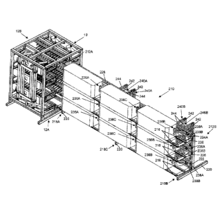
Figures 16 through 25 illustrated a bale feeding table 110 for feeding
bales into the above described bale dryer. The feeding table 110 features a
framework structure 112 defining a number of elongated feed lanes of equal
quantity
to the number of bale spaces in the bale dryer 10, hence their being three
feed lanes
114A, 114B, 114C in the illustrated example in order to respectively feed
bales into
the three bale spaces of the bale dryer 10. A bottom plane of each lane is
defined by
CA 3076779 2020-03-24
25
a respective track composed of a pair of parallel elongated track rails 116
running in a
longitudinal travel direction, which matches the longitudinal travel direction
of the
dryer. The track rails 116 span a full length of the framework structure 112
in said
longitudinal travel direction, thus spanning from a proximal end 112A of the
table 110
that resides adjacent the front end 12A of the bale dryer 10 when the feeding
table
110 is installed in working relation thereto, all the way to an opposing
distal end 112B
of the table 110 that resides distally opposite the bale dryer 10 in the
installed state of
the feeding table 110. The elevation of, and the spacing between, the track
rails 116
of the feeding table 110 matches those of the holder rails 34 of the bale
dryer's three
bale holders 32. The track rails 116 serve the same purpose as the holder
rails, thus
allowing seated support of the bales on the track rails 116, as well as
sliding
displacement of the bales thereatop.
The framework structure 112 features three ground leg assemblies
seated on the ground in order to support the track rails 116 in spaced
elevation
thereover at longitudinally spaced positions along said track rails 116. A
proximal leg
assembly 118A resides at the proximal end 112A of the framework structure 112,
a
distal leg assembly resides at the distal end 112B of the framework structure
112, and
a middle leg assembly 118C resides approximately midway between the proximal
and
distal leg assemblies. Each leg assembly features a pair of upright ground
legs 120
disposed at laterally opposite sides of the framework structure 112, and one
or more
lower cross-beams 122 spanning laterally between the two upright legs 120. The
outer two lanes 114A, 114C that reside adjacent the two laterally opposing
sides of
the feeding table 110 each have one their two track rails 166 mounted atop the
ground legs 120 that reside at the respective side of the framework structure
112.
The other track rails 116 are mounted atop respective rail support posts 124
that
CA 3076779 2020-03-24
26
stand upright from the cross-beams 122 of the leg assemblies.
Like the buffer rails 44 of the bale holders 32 in the bale dryer 10, the
feeding table 110 likewise feature buffer rails 126 running parallel to the
longitudinal
track rails 116 at a slightly greater elevation thereabove at positions
between adjacent
track rails 116 of adjacent lanes of the feeding table. These buffer rails 126
are
supported in the same manner as those of dryer, by small uprights 127 mounted
atop
short stub-like cross-members 128 connected between the adjacent track rails
116 of
adjacent lanes. Also like the bale dryer 10, the feeding table 110 features a
pair of
outer guide rails 130 running parallel to the buffer rails 126 at the opposing
lateral
sides of the feeding table. Accordingly, the bales placed on the track rails
116 in each
outer lane 114A, 114C are laterally constrained between the respective outer
guide
rail 130 and a respective one of the buffer rails 126, while the bales placed
on the
track rails 116 in the center lane 1140 are laterally constrained between the
two buffer
rails 126. The outer rails are shown schematically without mounting details,
but may
be attached to the nearest track rail 116, or to the set of ground legs at the
respective
side of the framework structure 112, by any suitable support means.
Each lane 114A, 114B, 114C is equipped with a respective bale mover
132 operable to move a respective group of bales queued in that lane in an
advancing
direction through said lane toward the proximal end 112A of the feeding table
110,
and into the bale dryer through the neighbouring front end 12A thereof. In
this
embodiment, each bale mover 132 has two distinct modes of bale engagement,
each
performed by a respective movable engagement unit of the bale mover, namely a
bale lifter 134 responsible for lifting of one or more queued bales upwardly
off of the
track rails 116 of the respective lane, and a bale pusher 136 responsible for
pushing
of a leading bale into the bale dryer from the proximal end 112A of the
feeding table
CA 3076779 2020-03-24
27
110.
The bale lifter 134 comprises a narrow and elongated lifting platform 138
spanning longitudinally of the respective lane within the laterally measured
horizontal
space between the two respective track rails 116 of the lane. The lifting
platform is
movable between a lowered position residing at an elevation below the lane's
bottommost plane, which is denoted by the coplanar topsides of the two track
rails,
and a raised position residing at an elevation slightly above this bottommost
plane of
the lane. Accordingly, the bale lifter's lowered position places it entirely
outside, and
more particularly below, the respective lane; while the bale lifter's raised
position
protrudes upwardly into the respective lane to engage with the underside of
one or
more queued bales of that lane to lift said bale(s) up off the track rails
116. The
raised position of the lifting platform 138 thus denotes a working position of
physical
engagement with one or more bales.
The bale movers 132 share a common movable subframe 140 that
carries both the bale lifter 134 and the bale pusher 136 of each bale mover
132. This
subframe 140 is longitudinally displaceable relative to the framework
structure 112
below the track rails 116 thereof. The subframe of the illustrated example has
a
skeletal box structure, of which a proximal end 140A resides between the
proximal
and middle leg assemblies 118A, 118C of the table's framework structure 12 in
a
proximal section thereof, while a distal end 140B of the subframe's skeletal
box
structure resides between the distal and middle leg assemblies 118B, 118C in a
distal
section of the table's framework structure 12. Bottom longitudinal rails 141
of the
subframe 140 are supported in longitudinally slidable fashion, for example
atop a set
of skid plates that are mounted atop a pair of longitudinal support rails 142
that span
between the proximal and distal leg assemblies 118A, 118B atop the lower cross-
CA 3076779 2020-03-24
28
beams 122 thereof at respective positions beneath the two outer lanes 114A,
114C.
The lifting platform 138 of each bale lifter 134 resides above the subframe
140 and
spans the full length thereof in the longitudinal direction. Each lifting
platform 138 is
supported near its proximal end by a respective upright arm 144A of an output
link of
a proximal lifting linkage 146A that is mounted to the subframe near the
proximal end
140A thereof. The opposing distal end of each lifting platform 138 is
supported by a
respective upright arm 144B of a matching distal lifting linkage 146B that is
mounted
to the subframe near the distal end 140B thereof. The three upright arms 144A,
144B
of the output link of each lifting linkage 146A, 146B are rigidly coupled
together by a
cross-bar 148 of the output link that lies in the lateral direction of the
feeding table 110
(i.e. horizontally perpendicular to the longitudinal travel direction
thereof), and is
pivotally pinned to the two bottom longitudinal rails 141 of the subframe.
With reference to Figure 26, at least one of the two lifting linkages 146A,
146B is driven by a respective actuator, for example a hydraulic cylinder 147
that has
one end pivotally coupled to a respective one of the bottom longitudinal rails
141 of
the subframe 140 via a mounting bracket on an inner side thereof, and the
other end
pivotally coupled to an input link 149 of the lifting linkage that is
pivotally coupled to
the bottom longitudinal rails 141 of the subframe. The input link in the
illustrated
example features a lever arm 149A that is situated just inside the respective
bottom
longitudinal rail 141 of the subframe, and to which the hydraulic cylinder 147
is
pivotally pinned. A cross-beam 149B of the input link has its opposing ends
pivotally
pinned to the two bottom longitudinal rails 141 of the subframe 140 via
mounting lugs
141A mounted thereatop, thereby forming the input link's pivotal connection to
the
subframe 140.
Extension of the hydraulic cylinder 147 pivots the input link 149 on one
CA 3076779 2020-03-24
29
direction forcing the upright arms 144A of the output link upward to lift the
respective
end of the lifting platforms 138, while collapse of the hydraulic cylinder 147
pivots the
input link 149 in the reverse direction lowering the upright arms 144A of the
output link
back down to lower the respective end of the lifting platforms 138. If both
lifting
linkages having respective hydraulic cylinders 147, these cylinders are
operated in
synchronous fashion so that both ends of the platforms 138 are likewise lifted
and
lowered in synchronous fashion to maintain a horizontal orientation of the
lifting
platform 138 throughout its movement between the lowered and raised positions.
In
the illustrated example however, only one of the two lifting linkages is
powered by a
respective hydraulic cylinder, and a connecting link 150 is pivotally pinned
between
the input links 149 of the two lifting linkages 146A, 146B to cause the
synchronous
movement thereof.
The cross-beam 148 of each lifting linkage's output link is pivotally
pinned to the lever arms 149A of the input link via a pair of coupling lugs
affixed to the
underside of the cross beam 148. The pivotally pinned connection between the
lever
arms 149A of the input link 149 and the coupling lugs of the output link
resides above
the pivotally pinned connection of the lever arms 149A to the mounting lugs
141A of
the subframe 140. The pivotally pinned connection between the hydraulic
cylinder
147 and the respective lever arm 149A is below the pivotally pinned connection
between the lever arms 149A and the mounting lugs 141A. Accordingly, extension
of
the hydraulic cylinder 147 raises the output link and attached lifting
platforms 138,
while collapse of the hydraulic cylinder 147 lowers the output link and
attached lifting
platforms 138.
The proximal lifting linkage 146A resides in the proximal section of the
framework structure 112 with the proximal end 140A of the subframe 140, and
the
CA 3076779 2020-03-24
30
distal lifting linkage 146B resides in the distal section of the framework
structure 112
with the distal end 140B of the subframe 140. In addition to the one or more
hydraulic
cylinders 147 actuating the lifting linkages (the "lifting cylinder(s)"), an
additional
hydraulic cylinder 152 of substantially greater length is operable to
longitudinally
displace the subframe 140 back and forth along the tracks of the three lanes,
and is
therefore referred to as the "displacement cylinder" 152. The displacement
cylinder
has one end coupled to the distal leg assembly 118B in the distal section of
the
framework structure 112, and the other end coupled to the subframe 140 near
the
proximal end 140A thereof in the proximal section of the framework structure
112.
The reach of the displacement cylinder 152 from one section of the framework
structure to the other is accommodated through a suitably placed opening in
the
middle leg assembly 118C.
Figures 16 to 19 show the subframe 140 and the three bale movers 132
carried thereby in a starting position with the distal end 140B of the
subframe 140
residing closely adjacent the distal end 112B of the framework structure 112,
and with
the proximal end 140A of the subframe 140 residing closely adjacent the middle
leg
assembly 118C at the approximate longitudinal midpoint of the framework
structure.
Extension of the displacement cylinder 152 moves the subframe and attached
bale
movers 132 in the advancing direction toward the proximal end 112A of the
framework structure 112. Figures 20 to 25 show the subframe 140 and the three
bale
movers 132 carried thereby in a fully advanced position achieved by full
extension of
the displacement cylinder 152, with the proximal end 140A of the subframe 140
residing closely adjacent the proximal end 112A of the framework structure
112, and
with the distal end 140B of the subframe 140 residing closely adjacent the
middle leg
assembly 118C. Figures 23 to 25 also show the bale litters 134 in the raised
position
CA 3076779 2020-03-24
31
with the lifting platforms 138 situated. above the track rails 116 in order to
lift queued
bales upwardly therefrom, whereas Figures 16 to 22 show the bale lifters 134
in the
lowered position which leaves the queued bales seated on the track rails 116.
The bale pusher 136 of each bale mover 132 comprises a spring-loaded
pusher arm 160 pivotally pinned to a respective proximal extension 162 of the
subframe 140. Each extension 162 protrudes longitudinally from the proximal
end
140A of the subframe, and thereby protrudes beyond the proximal end 112A of
the
feeding table 110 through an open proximal end of the respective lane when the
subframe 140 is in the fully advanced position. In this position, the subframe
extension 162 thus also reaches through the front end 12A of the bale dryer 10
into
an open space left between the holder rails 34 of the respective bale holder
32 and in
front of the respective lower manifold 14B. The pusher arm 160 is rotatably
journaled
on a small stub shaft that spans in the lateral direction between two sides of
the
respective subframe extension 162. The pusher arm 160 is spring biased into a
default working position angling obliquely upward from the subframe extension
162 in
a direction sloping upwardly away from the subframe 140, and reaching an
elevation
greater than that shared by the topsides of the feeding table's track rails
116 and the
bale dryer's holder rails 34.
In this default working position, the pusher arm 160 is operable during
advancement of the bale movers 132 to push on the distal/trailing end of any
bale that
leads the pusher arm 160 in the advancing direction, thereby pushing such bale
initially toward the proximal end 112A of the feeding table, and eventually
off this end
of the feeding table 110 and into the bale dryer 10. As shown, the pusher arm
160
may carry a smaller pusher bar 164 lying cross-wise thereto at the working end
thereof that resides in the lane and bale space in the working position of the
bale
CA 3076779 2020-03-24
32
pusher in order to increase the contact area with the bale to ensure the bale
pusher
pushes, rather than penetrates, the distal/trailing end of the bale during
advancement
of the bale mover 132. The illustrated bale pushers thus have a T-shaped
configuration created by the combination of the pusher arm and cross-wise
pusher
bar.
Having described the feeding table 110, attention is now turned to its
use, as illustrated in Figures 28A to 28S. These figures also illustrated how
multiple
dryers may be placed in longitudinal series with one another, with the rear
end of a
first dryer 10A fed by the feeding table 110 being placed in adjacent and
communicating relation with the front end of a second dryer 10B in order to
form a
multi-dryer setup of greater capacity than the single dryer 10 of the earlier
figures, but
while using only a singular shared feeding table 110. A third dryer may be
subsequently added in series with the second dryer at the rear end thereof,
and so
on.
Firstly, it is pointed out that the feeding table 110 in the illustrated
example has an overall length exceeding the collective length of three
rectangular hay
bales, but optionally less than the collective length of four rectangular hay
bales, to
enable three hay bales to be seated on the track rails of each lane with the
bale
lengths oriented longitudinally of the feeding table 110 so as to lie in end-
to-end
relation to one another, but with some clearance space left between them. In
this
example of a three-bale lane capacity, the length of the lifting platform 138
in each
lane exceeds the collective length of two bales, but is less than three hay
bales, to
enable lifting of two adjacent bales in the respective lane by the lifting
platform. The
length of the lifting platform 138 is therefore approximately two-thirds of
the overall
length of the feeding table, as measured between the proximal and distal ends
112A,
CA 3076779 2020-03-24
33
112B of its framework structure 112.
Referring to Figure 28A, three bales Bi, B2, B3 are queued in each lane
atop the track rails 116 thereof, of which the bale nearest to the dryers is
referred to
as the first bale, followed by the second bale, which in turn is followed by
the final
third bale of the queued group. With the three bale movers 132 in the starting
position, the lifting platform of each bale mover thus underlies the second
and third
bales 82, B3 nearest to the distal end 112B of the feeding table 110. The
second and
third bales may also be referred to as "trailing" bales, distinguished the
first leading"
bale Bi that is nearest to the proximal end 112A of the feeding table 110, and
will thus
will lead the remaining "trailing" bales in the advancing direction into the
dryers.
Figure 28A represents a "ready" state of the feeder/dryer setup, where a
current
group of three bales Bi, B2, 83 are queued in each lane of the feeding table
110 and
the dryers 10A, 10B are both in their open state with all manifolds thereof in
their
retracted positions ready to accommodate entry of bales into the bale spaces.
The
three locations along each lane at which the three bales reside at this ready
state are
referred to as sequential queuing "spots" through which the bales will be
indexed
forwardly in sequential fashion toward and into the dryers.
At the first step shown in Figure 288, the lifting platforms 138 of the bale
mover 132 are lifted into their raised working positions by extension of the
lifting
cylinder(s) 147, whereby the lifting platforms 138 engage the undersides of
the
second and third bales B2, B3 in each lane, and lift these trailing bales B2,
B3 up off
the track rails 116 of the feeding table. Next, with reference to Figure 28C,
the three
bale movers 132 are displaced in the advancing direction by extension of the
displacement cylinder 152, during which the bale pushers 136 push the leading
first
bale B1 of each lane toward and subsequently past the proximal end 112A of the
CA 3076779 2020-03-24
34
feeding table into the respective bale space of the first dryer 10A through
the front end
12A thereof. Meanwhile, the two trailing bales B2, B3 on the raised lifting
platform 138
of each bale lifter are likewise advanced toward the dryer by this
displacement of the
bale movers 132, thus moving each of these bales one spot closer to the dryers
10A,
10B.
Having fed the leading first bales Bi into the first dryer 10A, the bale
movers 132 then need to be reset back to the starting position. First, with
reference
to Figure 28D, the lifting platforms 138 of the three bale movers are lowered
back
down by collapse of the lifting cylinder(s) 147 to withdraw the lifting
platforms 138
from their respective lanes, thus reseating the two trailing bales B2, B3 of
each lane
back onto the track rails 116 thereof. The lowered position of the bale
lifters 134 is
thus also referred to as a reset position thereof, as it enables to the bale
movers 132
to be reset back to the starting position without moving or otherwise
disrupting the
trailing bales B2, B3 that were just seated back on the track rails 116 after
their initial
advancement atop the lifting platform 138. Turning to Figure 28E, the
displacement
cylinder 152 is collapsed, thus pulling the subframe 140 and three bale movers
132
back toward the starting position adjacent the distal end 112B of the feeding
table
110, during which the bale pushers 136 are pulled back against the leading
ends of
the second bales B2 of the three lanes. This causes pivoting of each bale
pusher 136
downwardly against its biasing spring force, until the bale pusher 136 clears
the
bottom perimeter edge of the leading end of the second bale B2 of the
respective
lane- As a result, the bale pusher 136 can subsequently ride along the
underside of
the second bale B2 during continued retraction of the bale movers 132, as
shown in
Figure 28F.
As shown in Figure 28G, as retraction of the bale movers 132 back
CA 3076779 2020-03-24
35
toward the starting position continues, the bale pushers 136 pop back up into
their
respective lanes as they clear the trailing ends of the second bales B2.
Meanwhile, at
anytime during the steps shown in Figures 28C through 28G, a new fourth bale
B4
(i.e. the leading bale of a next group of three bales, which in the drawings
distinguished from the first group of bales by way of broken line
illustration) has been
loaded into each lane at the distalmost spot thereof that was opened up during
the
first advancement of the bale movers 132 in Figure 28C. Turning to Figure 28H,
once
the bale movers 132 have been fully returned to the starting position, the
bale lifters
134 are actuated again by extension of the lifting cylinder(s) 147 to lift the
third bale
B3 (i.e. the final bale of the original group of three) of each lane again,
this time
together with the newly added fourth bale B4.
As shown in Figure 281, the bale movers 132 are advanced once again
by extension of the displacement cylinder 152, which causes the bale pushers
136 to
push the three second bales B2 into the first dryer 10A, which in turn push
the three
leading first bales Bi onward through the first dryer 10A and into the three
bale
spaces of the second dryer 10B. Meanwhile, this second advancement of the bale
movers 132 also carries the third and fourth bales B3, B4 of each lane one
spot
forward on the feeding table 110, thus moving the third bale B3 of each lane
into the
proximal spot thereof nearest to the dryers 10A, 10B, and also moving the
fourth bale
84 of each lane into the intermediate spot next closest to the dryer. At this
point, all
bale spaces in the two dryers 10A, 10B are now occupied by respective bales
Bi, B2,
and so the spear-equipped air manifolds 14A, 14B of the two dryers are moved
to
their deployed positions by extension of the linkage actuators 66, thereby
driving the
aeration spears 40 into penetrating relation to the received bales B1 , 82, as
shown in
Figure 28J. At this point, the one or more fans feeding the forced air to the
manifolds
CA 3076779 2020-03-24
36
14A, 14B of the two dryers 10, 10B are activated, and left running for a
drying cycle of
selected or predetermined duration.
As the drying cycle runs, the bale lifting platforms 138 are once again
lowered by collapse of the lifting cylinder(s) 147, as shown in Figure 28K,
thus
lowering the third and fourth bales B3, B4 of each lane back onto the track
rails 116 of
the feeding table 110. The bale movers are then again reset back .to the
starting
position by collapsing the displacement cylinder 152, as shown in Figure 28L.
During
this retraction, the bale pushers 136 are once again deflected down into their
lowered
reset positions by contact with the leading ends of the third B3, and then
allowed to
run along the undersides thereof. As shown in Figure 28M, once the bale movers
132
have fully returned to their starting position, completion of the drying cycle
is awaited.
Meanwhile, at anytime during the steps shown in Figures 281 through 28M, a new
fifth
bale B5 (i.e. the second bale of the second group of three) is loaded into
each lane at
the distalmost spot thereof that was opened up during the second advancement
of the
bale movers 132 in Figure 281.
Turning to Figure 28N, once the first drying cycle is complete, the fan(s)
is/are turned off to discontinue the forced air supply to the manifolds 14A,
14B and
aeration spears 40 of the dryers 10, 10B, and the manifolds are moved back to
their
retracted positions by collapse of the linkage assembly actuators 66, thereby
withdrawing the aeration spears 40 from the dried bales 131, B2 and reopening
the
dryers. Also at this stage, the lifting platforms 138 of the bale movers 132
are once
again lifted into their raised working positions by extension of the lifting
cylinder(s)
147, whereby the lifting platforms 138 engage the undersides of the fourth and
fifth
bales B4, B5 in each lane, and lift these bales B4, B5 up off the track rails
116. Next,
turning to Figure 280, the bale movers 132 are once again advanced by
extension of
CA 3076779 2020-03-24
37
the displacement cylinder 152, during which the bale pushers 136 push the
third and
final bales B3 of the first group off the proximal end 112A of the feeding
table 110 and
into the bales spaces of the first dryer 10A. This in turn pushes the leading
first bale
B1 of each lane out of the second dryer 10B at the rear end 12B thereof, where
a
receiving table of matching lane quantity to the feeding table (but lacking
the bale
movers thereof) may be positioned to accept discharged bales from the dryers.
This
same displacement of the bale movers 132 advances the fourth and fifth bales
B4, B5
of each lane to the proximal and intermediate spots thereof, whereupon the
lifting
platforms 138 of the three bale movers 132 are lowered back down to reseat the
fourth and fifth bales B4, B5 at these newfound spots.
Though at this time all bale spaces of the two dryers 10A, 10B are
occupied by respective bales B2, B3, the spear-equipped air manifolds 14A, 14B
are
yet not deployed for a second drying cycle, as the second bales B2 now
residing in the
second dryer 10B were already dried in the first dryer 10A during the first
drying cycle.
So instead, with reference to Figure 28P, the bale movers 132 are retracted
back to
the starting position, and a new sixth bale B6 (i.e. final bale of the second
group of the
three bales) is loaded into each lane of the feeding table 110 at the
distalmost spot
thereof. The lifting platforms 138 are again raised to lift the fifth and
sixth bales 85, B6
of each lane up off the track rails 116, and the bale movers are advanced
again to
push the fourth bale B4 of each lane into the first dryer 10A, thereby pushing
the third
bale B3 of each lane out the rear end 12B of the second dryer 10B, while also
shifting
the fifth and sixth bales B5, B6 forward one spot in the advancing direction,
as shown
in Figure 28Q. Now the second dryer 10B is occupied by the undried third bales
B3
and the first dryer 10A is occupied by the undried fourth bales B4.
Accordingly, the air
manifolds 14A, 14B are deployed again by extension of the linkage actuators 66
in
CA 3076779 2020-03-24
38
order to penetrate the aeration spears 40 into the third and fourth bales
83,84, as
shown in Figure 28R. The one or more fans are now activated again for the
selected
or predetermined drying cycle duration. Completion of this second drying cycle
denotes completion of a full drying process on the first group of bales Bi,
B2, B3, and
in the illustrated dual-dryer setup where two bales of each lane are dried
simultaneously, also serves to dry the leading bales 84 of the second group,
the
remaining bales B5, B6, of which will be dried in the next drying cycle. As
shown in
Figure 28S, during execution of the second drying cycle, the bale movers 132
are
once again retracted to the starting position so that the forgoing drying
process
collectively illustrated by Figures 28A through 28S can be repeated to finish
the drying
of the second group of bales
In the instance of a single-dryer setup lacking the second dryer 10B
behind the first dryer 10A that's directly loaded from the feeding table 110,
the
forgoing process follows the same general sequence of repeatedly lifting,
advancing
and retracting the bale movers 132, but differs only in terms of the quantity
and
frequency of drying cycles. In the single-dryer instance, the air manifolds
14A, 146 of
the table-fed dryer 10A are first deployed upon completion of the bale movers'
first
advancement pushing the first bales Bi into the dryer, i.e. at the step shown
in Figure
28D. In such case, the first drying cycle operates on the first bales Bi
during the first
retraction of the bale movers 132 back to the starting position in accordance
with
Figures 28E and 28F. With the bale movers fully reset at the starting position
in
Figure 28G, completion of the first drying cycle and retraction of the air
manifolds 14A,
14B is awaited, before initiating the next bale lifting and advancement steps
of Figures
28H and 281, during which the already dried first bale 61 is pushed out the
rear end of
the sole dryer 10A instead of into a second dryer.
CA 3076779 2020-03-24
39
The steps shown in Figures 28J through 280 are then performed in the
same manner as described above, except that the drying cycle executed therein
is the
second such drying cycle in a single-dryer setup and dries only the second
bales B2.
and the pushing of third bales B3 into the table-fed dryer 10A in accordance
with
Figure 280 pushes the second bale B2 out the rear of the sole dryer 10A
instead of
into a second dryer. A third deployment of the air manifolds and execution of
a third
dryer cycle is performed upon completion of the bale movers' third advancement
pushing the third bales B3 into the dryer, i.e. at the step shown in Figure
280,
whereby this third drying cycle operates on the third bales B3 during the
third
retraction of the bale movers 132 back to the starting position in Figure 28P.
In the
single-dryer instance, steps 28Q through 28S would denote initial steps of a
subsequent drying operation on a second group of three bales.
While the feeding table 110 in the illustrated embodiment is designed to
queue three bales in each lane and carry two bales atop the lifting platform
138, a
shorter feeding table may be used to queue only two bales in each lane and
accordingly carry only one bale on a shorter lifting platform. Alternatively,
a longer
feeding table may be designed to queue four bales in each lane, and carry
three bales
atop a longer lifting platform. The table may be made even longer to even
further
increase the bale queuing capacity, with the bale capacity of the lifting
platform of
each lane being one less that the overall lane capacity. So if the lane
capacity is CL
and the platform capacity is CP, then the platform capacity is calculated as
Cp= CL -1
for feed tables of the forgoing type where the first leading bale Bi in each
lane is
pushed in the advancing direction by the bale pusher 136 of the respective
bale
mover, and any subsequent trailing bales B2...BN (where N = Cp) in that lane
are
indexed forward by one spot by the raised lifting platform of the respective
bale
CA 3076779 2020-03-24
40
mover. While the illustrated embodiment features three queuing lanes for
feeding a
dryer with three bale spaces, a single lane or dual lane feed table may be
used with a
single or dual space bale dryer, or the number of table lanes and
corresponding dryer
bale spaces may be increased from the illustrated three-lane, three-space
embodiment. It will also be appreciated that a feeding table of the present
invention
may be used in combination with a bale dryer other than the novel bale dryer
disclosed herein.
Figures 29 through 36 illustrate a second embodiment dryer 10', which
is nearly identical in construction to the first embodiment dryer 10 of
Figures 1 through
8, but having been turned onto one of its sides and then propped up at a
slightly tilted
angle of inclination in the lateral direction by an angled base stand 212
installed
beneath the reoriented support frame. As a result, instead of the manifolds
14A, 14B
being arranged in top and bottom sets situated respectively above and below
the
three horizontally adjacent bales spaces of the dryer, the manifolds 14A, 14B
are
disposed in left and right sets situated on different respective sides of
three vertically
adjacent bale spaces of the dryer. The former buffers rails 44, 44' now serve
as the
holder rails at the bottom of the upper two bale spaces and as the constrainer
rails at
the top of the lower two bale spaces. The singular guide rail 45 at each of
the two
lateral sides of the earlier embodiment is now replaced with a pair of
longitudinal rails,
of which the pair 45 now residing at the bottom of the support frame define
the two
holder rails of the lowermost bale space, and the pair residing at the top of
the support
frame define the two constrainer rails at the top of the uppermost bale space.
Other
than this doubling of these rails 45, and the optional addition of the angled
base frame
212 for reasons explained below, the construction of the dryer 10' is the
same, just
reoriented in space. The former holder rails 34 and constrainer rails 34' now
serve as
CA 3076779 2020-03-24
41
guide rails at opposing sides of each bale space to maintain alignment of the
bale
received therein, and are supported by the same standoffs 36 as before, the
latter of
which now jut laterally inwardly from the sides of the support frame rather
than
hanging downward and standing upward from the top and bottom of the support
frame.
The linkage assemblies 16, 18 and associated actuators 66 are the
same as before, but now referred to as left and right linkage assemblies 16,
18 rather
than upper and lower linkages assemblies, and now pivot about upright axes
rather
than horizontal lateral axes in order to move the manifolds 14A, 14B laterally
side-to-
side into and out of the deployed positions to drive the aerations spears into
and out
of the bale spaces laterally rather than vertically. The second embodiment is
thus
substantially the same in construction and operation, but the bale spaces
reside one
over the other in vertically spaced relation to one another rather than side-
by-side in
horizontally spaced relation to one another, and the manifolds and attached
aeration
spears move laterally side to side rather than vertically and up and down so
as to
penetrate the bales from opposing sides thereof rather than from above and
below the
bales.
Figure 37 through 42 illustrated the second embodiment bale dryer 10'
being used in combination with an upright bale feeding rack 210 that replaces
the
horizontal bale feeding table 110 of the earlier embodiment. Like the earlier
feeding
table 110, the feeding rack 210 features a framework structure 212 defining a
number
of elongated lanes of equal quantity to the number of bale spaces in the bale
dryer
10', hence their being three lanes 214A, 214B, 214C in the illustrated example
in
order to respectively feed bales into the three bale spaces of the bale dryer
10'.
However, the three lanes 214A, 214B, 214C of the feeding rack 210 are
organized in
CA 3076779 2020-03-24
42
an upright stack situated in vertically spaced relation one over another, as
opposed to
the side-by-side horizontal layout of the feeding table 110. Once again, a
bottom
plane of each lane is defined by a respective track composed of a pair of
parallel
elongated track rails 216 running in a longitudinal travel direction matching
that of the
dryer 10'. The track rails 216 span a full length of the framework structure
212 in said
longitudinal direction between a proximal end 212A thereof that resides
adjacent the
front end 12A of the bale dryer 10' when the feeding rack 210 is installed in
working
relation thereto, and an opposing distal end 212B that therefore resides
distally
opposite the bale dryer 10' in the installed state of the feeding rack 210.
The
elevation of, and the spacing between, the track rails 216 of each lane of the
feeding
rack 210 matches those of the holder rails 45, 44, 44' of a corresponding one
of the
bale dryer's three bale spaces, and serve the same purpose of allowing seated
support of the bales on the rails 216, as well as sliding displacement of the
bales
therealong.
The framework structure 212 once again features three ground leg
assemblies seated on the ground to support the track rails 216 in spaced
elevation
thereover at longitudinally spaced positions along said track rails 216,
namely a
proximal leg assembly 218A residing at the proximal end 218A of the framework
structure 212, a distal leg assembly residing 218B at the distal end 212B of
the
framework structure 212, and a middle leg assembly 218C residing approximately
midway between the proximal and distal leg assemblies. Each leg assembly
features
a horizontal ground member 220 seated atop the ground and spanning in the
lateral
direction perpendicular to the longitudinal travel direction. At or near a
midpoint of the
ground member 220, each leg assembly features an upright stanchion 222
standing
upward from the ground member 220. These upright stanchions 222 are parallel
to
CA 3076779 2020-03-24
43
the corner posts of the support frame of the bale dryer 10', and therefore in
the
illustrated example of the slightly tilted dryer orientation, instead of lying
truly vertical,
lie at a small oblique angle to vertical.
Over the full length of the feeding rack 210, from one leg assembly to
the next, spans a pair of upper and lower beams 224A, 224B that horizontally
and
longitudinally interconnect all three leg assemblies and are affixed to the
respective
stanchions 222 thereof. The upper beam 224A is mounted at the top ends the
stanchions 222, and the lower beam 224B is mounted near the bottom end of the
stanchions 222, though at a spaced elevation above the ground members 220 in
order to leave some ground clearance below the lower beam 224B. In the
illustrated
example, the upper beam 224A is a singular beam of continuous length that lies
atop
the stanchion 222 of the middle leg assembly 218C, while the lower beam 224B
is a
split beam having two discrete halves each spanning between the middle leg
218C
assembly and a respective one of the proximal and distal leg assemblies 218A,
218B.
The two halves of the lower beam 224B are thus interrupted by the stanchion
222 of
the middle leg assembly 218C, while the upper beam instead caps off the top
end of
that stanchion 222. The upper and lower beams 224A, 224B and the upright
stanchions 222 collectively define an open-framed skeletal wall running
longitudinally
of the framework structure in a slightly tilted plane matching the slight
angular tilt of
the bale dryer 10'. It is this skeletal wall, supported in such orientation by
the ground-
seated positions of the ground members 220, that supports the other working
components of the feeding rack 210, as outlined in more detail below.
The two track rails 216 of each lane are supported in cantilevered
fashion from the skeletal wall by a set of three cantilever arms 226 whose
mounted
ends are respectively affixed to the upright stanchions 222 of the three leg
assemblies
CA 3076779 2020-03-24
44
at right angles thereto. The cantilever arms 226 are thus oriented
perpendicularly to
the slightly oblique plane of the skeletal wall, whereby the cantilever arms
226 have a
slight upward incline in an outward direction from that plane. The two track
rails 216
of each lane are mounted in coplanar and parallel relation to another atop the
respective set of cantilever arms 226, and are thus situated at slightly
different
elevations. The outer track rail that is situated furthest from the skeletal
wall is thus
situated at slightly higher elevation than the inner track rail that is
situated nearer to
the skeletal wall. As a result, when a hay bale is placed on the two track
rails 216 of
any lane 214A, 214B, 214C of the feeding rack 210, the bale is gravitationally
biased
toward the skeletal wall.
In the proximal section of the feeding rack 210 residing between the
proximal and middle leg assemblies 218A, 218C, a set of three horizontally and
longitudinally extending resting rails 228 each run along a respective one of
the three
lanes 21A, 214B, 2140 at the lateral side thereof nearest the skeletal wall.
Each such
resting rail 228 is supported near its longitudinally opposing ends by a
respective pair
of cantilever stubs 230 of matching directionality to, but shorter length
than, the
cantilever arms 226 that support the two track rails 216 of the respective
lane. The
resting rails 228 of the lower two lanes have their respective cantilever
stubs 230
affixed to the stanchions 222 of the proximal and middle leg assemblies 218A,
218C.
The uppermost lane has its respective resting rail 228 supported by a pair of
right
angle brackets 231 that stand upright from the upper beam 224A of the skeletal
wall
in coplanar relation therewith, and then turn perpendicularly outward
therefrom to
carry the respective resting rail 228 above and outward from the skeletal
wall. These
resting rails 228 reside in a shared common plane that lies parallel to the
obliquely
angled plane of the skeletal wall, and denotes a lateral side of each lane
nearest to
CA 3076779 2020-03-24
45
said skeletal wall, which is referred to as an "inner side" of the lane. At an
opposing
outer side of the lanes, each lane is left open to allow placement of bales
into the
lanes from this open outer side. The gravitational bias of the hay bales
toward the
skeletal wall will thus bias them into resting contact with the resting rails
228, against
which the hay bales can rest when seated on, or sliding along, the track rails
216 at
the proximal section of the rack 210. The slightly oblique tilt of the feeding
rack 210,
and corresponding tilt of the dryer 10' so that the lanes of the tilted
feeding rack
properly align with the bale spaces of the tilted dryer, thus prevents hay
bales from
potentially falling from the open outer side of the rack.
The feeding rack 210 features three bale movers 232, one for each lane.
Each bale mover 232 is configured to displace a respective group of three
bales
forwardly along the feeding rack into the dryer one at a time, much like the
feeding
table 110 of the earlier embodiment. However, whereas the bale movers of the
feeding table employed a two-bale bale lifter to displace the two trailing
bales through
a lift and carry action, and a separate singular bale pusher to simply slide
the leading
bale into the dryer without lifting, each bale mover 232 of the feeding rack
210 uses a
set of three bale pushers 236A, 236B, 236C to respective displace the three
bales
purely through sliding motion on the track rails 216 without any lifting
action, and
accordingly lacks any separate bale lifter. The bale pushers 236A, 236B, 236C
are of
similar structure and operative function to those of the earlier table
embodiment, but
reoriented and repositioned relative to the track rails 216 to accommodate the
different between the upright rack context of the present embodiment and the
horizontal table context of the earlier embodiment.
Each bale mover 232 features a pair of longitudinally and horizontally
oriented resting bars 238A, 238B lying parallel to and coplanar with the
resting rails
CA 3076779 2020-03-24
46
228 of the framework structure 212. The length of these resting bars 238A,
238B is
equal or similar to that of the lifting platform 138 of the earlier
embodiment, thus
exceeding the length of two rectangular hay bales. For brevity, each pair of
resting
bars 238A, 238B is referred to as a "bale rester' 238 of the respective bale
mover, as
two out of three bales being moved by the bale mover at any time will rest
against
these bars 238A, 2386 during such movement, much like the two trailing bales
in the
feeding table embodiment rested on the raised lifting platform 138 during such
movement. The three bale resters 238 are rigidly interconnected so as to cause
synchronous movement of the all three bale movers 132 back and forth along the
framework structure in the longitudinal travel direction.
Such rigid interconnection in the illustrate embodiment is accomplished
by a proximal subframe 240A attached to the bale resters 238 at or near the
proximal
ends thereof nearest the bale dryer 10', and a distal subframe 240B attached
to the
bale resters 238 at or near the distal ends thereof furthest from the bale
dryer 10'.
Each subframe 240A, 240B features two ladder-like units spaced a short
horizontal
distance apart in the longitudinal travel direction, each having an upright
stile 242
residing on the side of the skeletal wall opposite the track rails 216, and a
set of six
support rungs 244 jutting laterally from the stile 242 through open spaces of
the
skeletal wall to respectively connect to the six resting rails 238A, 238B of
the three
bale movers 232. Regardless of the position of the bale movers at any point in
time,
the proximal subframe 240A resides in a proximal section of the framework
structure
212 between the proximal leg assembly 218A and the middle leg assembly 218C,
and
the distal subframe 240B resides in a distal section of the framework
structure 212
between the distal leg assembly 218B and the middle leg assembly 218C.
The bale movers 232 are movably supported on the framework structure
CA 3076779 2020-03-24
47
212 for rolling longitudinal displacement therealong by a proximal wheel set
246A
rotatably carried on the proximal subframe 240A, and a matching distal wheel
set
246B rotatably carried on the distal subframe 240B. Each wheel set operates in
rolling contact with the upper beam 224A of the skeletal wall, and features an
upright
top wheel 248 and a pair of side wheels 250A, 250B. The top wheel 248 is
rotatably
supported about a laterally oriented rotation axis lying perpendicular to the
plane of
the skeletal wall and positioned for rolling contact with the topside of the
skeletal
wall's upper beam 224k The side wheels 250A, 250B are supported about
respective upright rotational axes of parallel relation to the skeletal wall
on opposite
sides thereof for rolling contact with opposing sides of the skeletal wail's
upper beam
224A. The top wheels 248 thus carry the subframes 240A, 240B and attached bale
movers 232 on the skeletal wall in hanging fashion from the top beam thereof
in
rolling relation therealong, while the side wheels stabilize the subframes and
attached
bale movers in the lateral direction. In the interest of clarity, so as not to
overcrowd
the drawings and obscure other details, the wheels axles and mounting details
thereof
are omitted, but options for rotatable mounting of the wheels of each set to
the
respective subframe will be apparent to those of skill in the art.
Longitudinal displacement of the bale movers 232 back and forth along
the rack is controlled by extension and collapse of a hydraulic cylinder 252
coupled
between the stanchion 222 of the distal leg assembly 218B and the proximal
subframe 240A that carries the proximal ends of the bale movers 232 on the
skeletal
wall of the framework structure 212. This hydraulic cylinder may once again be
referred to as the "displacement cylinder" due to its functional purpose,
despite the
lack of need to different over any "lifting cylinders", none of which are
employed in the
rack embodiment.
CA 3076779 2020-03-24
48
Each bale pusher 236A, 2366, 236C once again features a spring
loaded pusher arm 260 and a pusher bar 264 fixed to the working end thereof in
cross-wise relation thereto to impart a T-shaped configuration to the bale
pusher.
Each bale mover 232 features three bale pushers 236A, 236B, 236C, each
rotatably
journaled on a small stub shaft supported perpendicularly between the two
resting
rails 238A, 238B of the bale mover. The three bale pushers of each bale mover
include a proximal bale pusher 236A supported near the proximal end of the
bale
rester, a distal bale pusher 236B supported near the distal end of the bale
rester, and
a middle bale pusher 236C supported intermediately between the other two bale
pushers at or near a midpoint of the bale rester.
The space between each pair of bale pushers in each lane
accommodates the length of a singular hay bale therein. Each bale pusher is
spring
biased into a default working position angling obliquely through the shared
plane of
the resting rails 228 and resting bars 238A, 238B, and reaching longitudinally
toward
the dryer. The working position of each bale pusher 236A, 236B, 236C thus
reaches
laterally into the corresponding lane of the feeding rack from the inner side
thereof. In
this default working position, the pusher arm is operable during advancement
of the
bale movers 232 to push on the distal/trailing end of any bale that leads the
pusher
arm 260 in the advancing direction, thereby pushing such bale initially toward
the
proximal end 212A of the feeding rack, and eventually off the feeding rack 210
and
into the bale dryer 10'.
Using the displacement cylinder 252, the sequence of advancement and
retraction of the bale movers 232 to feed bales into the dryer 10' with the
feeding rack
210 are substantially the same as those described earlier for the feeding
table 110,
just without the lifting and lowering steps associated with the bale lifters
of the table
CA 3076779 2020-03-24
49
embodiment that are omitted in the rack embodiment. Figures 37 to 42 show the
ready state of the feeder/dryer setup, where a current group of three bales
are
queued in each lane of the feeding rack 210 and the manifolds of all bale
spaces in
the dryer are in their retracted positions ready to accommodate entry of bales
into the
bale spaces. As before, this state of the dryer with the manifolds and
attached spears
retracted may also be referred to as an "open" state of the dryer. The three
locations
along each lane at which the three bales reside at this ready state are again
referred
to as sequential queuing "spots", since bales will be indexed forwardly in the
advancing direction one spot at time in sequential fashion toward and into the
dryer
10'.
In the ready state, the three bale movers 232 reside in a starting position
with the distal subframe 240B residing closely adjacent the distal end 212B of
the
framework structure 212, and with the proximal subframe 240A residing closely
adjacent the middle leg assembly 118C at the approximate longitudinal midpoint
of
the framework structure 212. Extension of the displacement cylinder 252 is
operable
to move the subframes 240A, 240B and attached bale movers 232 in the advancing
direction toward the proximal end 212A of the framework structure 212. In a
fully
advanced position of the subframes 240A, 240B and attached bale movers 232,
shown in subsequent figures and achieved by full extension of the displacement
cylinder 252, the proximal subframe 240A instead resides closely adjacent the
proximal end 212A of the framework structure 212, and the distal subframe 240B
resides closely adjacent the middle leg assembly 118C.
At the first operational step shown in Figure 43A, the three bale movers
232 are displaced in the advancing direction by extension of the displacement
cylinder
252, during which the proximal bale pushers 136 push the first bale B1 of each
lane
CA 3076779 2020-03-24
50
toward and subsequently past the proximal end 212A of the feeding rack 210,
and
thus into the respective bale space of the dryer 10' through the front end 12A
thereof.
During their approach to the proximal end 212A of the feeding rack 210, these
first
bales B1 slide along both the track rails 216, and the resting rails 228 of
the rack's
proximal section, against which the first bales are gravitationally biased.
Simultaneously, the second and third bales B2, B3 of each lane are likewise
advanced
toward the dryer by this displacement of the bale movers 232, being
respectively
pushed in sliding fashion along the track rails 216 by the distal and middle
sets of bale
pushers 236B, 236C, but remaining in static relation to the moving resting
bars 238A,
238B of the bale movers, against which the second and third bales B2, B3 are
likewise
rested through gravitational bias.
Having fed the first bales Bi into the dryer 10', the bale movers 232 then
need to be reset back to the starting position. Turning to Figure 43B, the
displacement cylinder 252 is collapsed, thus pulling the bale movers 232 back
toward
the starting position, thereby returning the distal subframe 240B and adjacent
distal
ends of the bale movers back to the distal end 212B of the feeding rack 210.
During
this retraction, the proximal and middle bale pushers 236A, 236C are pulled
back
against the leading ends of the second and third bales B2,B3, respectively,
which
causes pivoting of these proximal and middle bale pushers 236A, 236C in
counteracting relation to their spring bias, until these proximal and middle
bale
pushers 136 each clear the inside perimeter edge (i.e. the upright perimeter
edge
nearest the skeletal wall of the rack) of the leading end of the respective
second or
third bale B2,B3. As a result, each proximal or middle bale pusher 236A, 236C
can
subsequently ride along the inner side of the respective second or third bale
B2,B3
during continued retraction of the bale movers 232, as shown in the top plan
view of
CA 3076779 2020-03-24
51
Figure 43B.
Meanwhile, since all bale spaces in the dryer 10' are occupied by the
first bales 131, the spear-equipped air manifolds 14A, 14B are moved to their
deployed
positions by extension of the linkage assembly actuators 66, thereby driving
the
aeration spears 40 into penetrating relation to the received first bales Bi,
as shown in
Figure 43C. At this point, the one or more fans feeding the forced air to the
manifolds
14A, 14B of the dryer 10' are activated, and left running for an appropriate
drying
cycle of selected or predetermined duration.
As shown in Figure 43D, as retraction of the bale movers toward the
starting position continues during the first drying cycle, the proximal and
middle bale
pushers 136 pop back out into their respective lanes as they clear the
trailing ends of
the second and third bales B2, B3. Turning to Figure 43E, once the bale movers
have
been fully returned to the starting position, a new fourth bale B4 (i.e. the
first bale of a
next group of three bales, which in the drawings distinguished from the first
group of
bales by way of broken line illustration) is loaded into each lane at the
distalmost spot
thereof that was opened up during the first advancement of the bale movers 232
in
Figure 43A. Turning to Figure 43F, once first drying cycle is completed, the
manifolds
14A, 14B and attached spears 40 are returned to their retracted positions,
thus
reopening the dryer 10'. Turning to Figure 43G, the bale movers 232 are then
advanced again by extension of the displacement cylinder 252, which causes the
proximal bale pushers 236A to push the second bales B2 into the dryer 10',
which in
turn pushes the first bales Bi out of the rear end 12B of the dryer 10'. The
steps of
Figures 43B to 430 are then repeated as many times necessary to dry the
quantity of
bales concerned.
While the forgoing example of the feeding rack operation is in a single-
CA 3076779 2020-03-24
52
dryer context, it will be appreciated it may be used in a dual-dryer context
like the
earlier illustrated feeding table example, in which case the dryer is only
closed for a
drying cycle with every second advancement of the bale movers. In other words,
the
frequency of the dryer closer and activation (measured in quantity of bale
mover
advancements) is equal to the number of dryers installed in series: in a
single-dryer
setup, the dryer is closed and activated with every individual advancement of
the bale
movers; in a dual-dryer setup, the dryer is closed and activated only every
second
advancement of the bale movers; in a triple-dryer setup, the dryer is closed
and
activated only every third advancement of the bale movers; etc.
Like with the feeding table 110, while the illustrated feeding rack 210 is
designed to queue three bales in each lane and accommodate two bales in
abutted
relation against the bale rester 238, a shorter bale rester may be used to
queue only
two bales in each lane and accordingly accommodate only one bale against the
bale
rester. Alternatively, a longer feeding rack 210 may be designed to queue four
bales
in each lane, and receive three bales against the bale rester 238. The feeding
rack
210 may be made even longer to even further increase the bale queuing
capacity,
with the bale capacity of the bale rester 238 of each lane being one less that
the
overall lane capacity. So if the lane capacity is CL and the rester capacity
is CR, then
the rester capacity is calculated as CR = CL -1 for feeding racks 210 of the
forgoing
type where the first leading bale Bi in each lane is pushed in the advancing
direction
by the proximal bale pusher 236A of the respective bale mover, and any
subsequent
trailing bales B2...BN (where N = CR) in that lane are indexed forward by one
spot by
the remaining bale pushers 236B, 236C of trailing relation to the proximal
bale
pusher. Like with the feeding table 110, while the illustrated feeding rack
210 features
three queuing lanes for feeding a dryer with three bale spaces, a single lane
or dual
CA 3076779 2020-03-24
53
lane feed rack may be used with a single or dual space bale dryer, or the
number of
rack lanes and corresponding dryer bale spaces may be increased from the
illustrated
three-lane, three-space embodiment. It will also be appreciated that a feeding
rack
210 of the present invention may be used in combination with a bale dryer
other than
the novel bale dryer disclosed herein. Furthermore, while the preferred
embodiment
has the dryer and rack lanes at a slightly tilted orientation to
gravitationally discourage
the falling of bales from the open side of the rack, while still allowing
initial loading of
bales into at any and all open spots due to the open-sided design of the rack,
for
example using a fork-equipped front end loader, other embodiments may omit the
tilted orientation, and employ a truly vertical configuration in which the
bale spaces of
the dryer, and the stacked queuing lanes of the rack, are in direct vertical
alignment
over one another.
Turning now to Figures 44A through 441, an alternate reconfiguration of
the dual dryer setup of earlier Figures 27 and 28 is shown for the purpose of
handling
round bales, instead of the rectangular bales of the earlier embodiments. In
the round
bale setup, a horizontal feeding table is once again situated in front of the
first dryer
10A' to load the bales into the front end 12A thereof, but is a single-lane
feeding table
310A that feeds a singular bale space of the first dryer, and is accompanied
by a
corresponding single-lane receiving table 310B situated behind the second
dryer 10B'
to receive bales existing the rear end 12B thereof. Though the manifolds and
aerations spears and operating linkages thereof are omitted in the schematic
illustration of the round bale embodiment, each single space bale dryer 10A',
10B',
instead of having top and bottom air manifolds above the bale space like first
embodiment dryer 10, has left and right air manifolds on opposite sides of the
bale
space like the second embodiment dryer 10'. Instead of a rectangular manifold
with a
CA 3076779 2020-03-24
54
rectangular array of aeration spears, the manifolds are circular and carry a
circular
array of aeration spears thereon to generally match the circular sides of the
round
bales in size and shape. Since round bales seated on straight rails would tend
to roll,
rather than slide, when pushed, the flat-topped holder rails 34 of the dryers
and flat-
topped track rails 116 of the rectangular bale feeding table are omitted in
the round
bale embodiment.
Instead of flat-topped track rails 116, each table 310A, 310B has a
respective pair of stationary bale holders 316A, 316B supported on its
framework
structure (riot shown), of which the bale holder closest to the dryers is
referred to as
the proximal bale holder 316A, and the bale holder furthest from the dryers is
referred
to as the distal bale holder 316B. Each bale holder 316A, 316B has a pair of
concave
seats 318A in the topside thereof, each having a suitable radius of curvature
to cradle
the convex underside of a respective round bale, thereby preventing rolling
motion of
the bale once seated on the bale holder. To move the round bales among the
bale
holders 316A, 316B and into and out of the bale spaces of the dryers 10A',
10B',
there is a bale mover 332 having a multi-section lifting platform 338, but
lacking any
bale pusher of the type described in the earlier table and rack embodiments.
Like the lifting 138 platform of the rectangular bale feeding table 110 of
the earlier embodiment, the lifting platform 338 is linearly displaceable in
the
longitudinal direction, whether by way one or more a hydraulic cylinders
(displacement cylinder(s)) or other options mentioned below, and is also
raiseable
and lowerable between a raised working position situated inside the lanes and
bale
spaces of the tables 310A, 310B and dryers 10A', 10B' to engage with the bales
situated thereon and therein, and a lowered reset position withdrawn from the
lanes
and bale spaces and disengaged from the bales to enable return of the lifting
platform
CA 3076779 2020-03-24
55
338 back an initial starting position. In this embodiment, the raised working
position of
the lifting platform 338 is one of elevated relation to the stationary bale
holders 316A,
316B of the tables 310A, 310B, as these bale holders 316A, 316B denote the
bottom
plane of the lane that was previously denoted by the track rails 116 in the
earlier table
embodiment for rectangular bales. The lowered reset position of the bale
platform
338 accordingly resides below the stationary bale holders 316A, 316B. Each
bale
holder 316A, 316B may be composed of a pair of parallel bars spaced laterally
apart
in a shared horizontal plane (like the track rails 116 of the earlier table
embodiment).
Each bar has two concave cutouts in the topside thereof that align with
matching
cutouts in the topside of the other bar to form the two concave seats 318A of
the bale
holder 316A, 316B. The bale lifting platform 338 can thus be raised and
lowered
between its two positions via the open space left between the two bars of each
bale
holder 316A, 3166, in the same way the spaced apart track rails 116 in the
earlier
table embodiment accommodated raising and lowering of the lifting platform 138
into
and out of the lane via the space between the track rails 116.
The lifting platform 338 is composed of four distinct sections 338A,
338B, 338C, 338D in the longitudinal direction, each section having a
respective pair
of cradle-shaped seats 318B therein of the same concave character as the
concave
seats 318A of the bale holders, thereby being suitable to cradle the convex
undersides of the round bales, unlike the flat-topped planar platform 138 of
the earlier
table embodiment that instead conformed to the planar undersides of the flat-
bottomed rectangular bales. The overall quantity of platform seats 318B is
equal to
the overall quantity of bale holder seats 318A. The longitudinal space between
the
two paired seats of each bale holder or platform section is identical, and the
longitudinal space from one pair of seats to the next pair of seats from bale
holder to
CA 3076779 2020-03-24
56
bale holder of either table, and from section to section of the lifting
platform, is
likewise uniform.
While the illustrated schematic shows the bale holders 316A, 316B of
each table 310A, 310B being distinctly separate of one another, it will be
appreciated
that they are nonetheless interconnected by a shared framework structure (not
shown), and optionally may also be directly connected to another, for example
as
integral parts of a pair of elongated bars that span a substantial entirety of
the table
length. Likewise, while the lifting platform 338 is shown in three distinctly
separate
parts, of which only the two middle sections 338B, 338C are directly
interconnected
as integral parts of an elongated platform structure, the level of direct
interconnection
between the different sections may be varied, provided that the different
platform
sections are sufficiently linked by physical structure or operational control
function to
move synchronously with one another during the operational sequence described
below. In the illustrated example, multiple sets of support wheels 340
rollably support
a travelling subframe (not shown) of the bale mover at longitudinally spaced
positions
therealong, with each bale section being movably mounted on this travelling
subframe
between two neighbouring sets of the ground wheels, and being raiseable and
lovverable relative to the subframe by one or more lifting actuators, for
example via
lifting linkages similar to those described in the earlier table embodiment.
In the ready state of the round bale feeder/dryer setup, a set of four
bales are seated in the four seats 318A of the two bale holders 316A, 316B of
the
feeding table 310A, for example having been placed in such positions from
beside the
table using a fork-equipped front end loader. The four bales Bi, B2, B3, B4
are
therefore queued in the singular lane of the feeding table 310A. Meanwhile,
the
dryers are in their open state, with the air manifolds of the bale spaces in
their
CA 3076779 2020-03-24
57
retracted positions ready to accommodate entry of bales into the bale spaces.
The
four seats 318A of the feeding table's bale holders 316A, 316B therefore
denote the
queuing spots of the feeding table in this embodiment. However, in the present
embodiment, instead of the bales being indexed forwardly in the advancing
direction
one spot at time in sequential fashion toward and into the dryers, each bale
is
advanced by two spots for each advancement of the bale mover 332, as will be
appreciated from the following description.
In the starting position of the bale mover 332, a distal loading section
338A of the lifting platform 338 resides at the distal bale holder 316B of the
feeding
table 310A, a proximal loading section 338B of the lifting platform 338
resides at the
proximal bale holder 316A of the feeding table 310A, a proximal unloading
section
338C of the lifting platform 338 resides inside the dryers 10A', 10B' below
the bale
spaces thereof, and a final distal unloading section 338D of the lifting
platform 338
resides at the proximal bale holder 316A of the receiving table 310B. The
distal bale
holder 316B of the receiving table is unoccupied by any section of the lifting
platform
338 in the starting position thereof. The starting position is thus that in
which the
lifting platform is at its closest to the distal end of the feeding table
310A, and at its
furthest from the distal end of the receiving table. The distal end of each
table 310A,
310B refers to the end thereof furthest from the dryers 10A', 108'.
The first step of the dryer loading process is shown in Figure 44A, where
all four sections of the lifting platform 338 of the bale mover 332 are lifted
into their
raised working position, for example by extension of one or more lifting
cylinders,
whereby the proximal and distal loading sections 338A, 3388 of the lifting
platform
engage the undersides of all four queued bales Si, B2, B3, B4 in the lane of
the
feeding table 310A, and lift all four queued bales Bl, B2 B3,134 up off the
bale holders
CA 3076779 2020-03-24
58
316A, 3168 of the feeding table 310A. Next, with reference to Figure 44B, the
bale
mover 332 is displaced in the advancing direction by one or more actuators,
for
example by extension of one or more displacement cylinders or by advancing
rotational drive of one or more wheel motors operating on one or more sets of
the
ground wheels 340. During such advancement, the proximal loading section 338B
of
the lifting platform 338 carries the first and second bales Bi, B2 past the
proximal end
of the feeding table 310A and into the dryers 10A', 10131, specifically
carrying the first
bale B1 fully through bale space of the first dryer 10A' into the bale space
of the
second dryer 10B', and carrying the second bale B2 into the bale space of the
first
dryer 10A'. This represents the fully advanced position of the lifting
platform 338, in
which the distal unloading section 338D thereof now occupies the distal bale
holder
316B of the receiving table 310B, while the proximal unloading section 338C
occupies
the proximal bale holder 316A of the receiving table 310B, the proximal
loading
section 338B now occupies the dryers 10A', 10B' and the distal loading section
338A
now occupies the proximal bale holder 316A of the feeding table 310k At this
point,
both dryers 10A', 10B' are then closed, thereby moving their air manifolds
into their
deployed positions spearing the first and second bales B1, B2 currently seated
atop
the proximal loading section 338B of the lifting platform 338, and the fan(s)
is/are
activated to initiate the first drying cycle on these two bales Bl, 62.
Next, with reference to Figure 44C, having been pierced with the
aeration spears from both sides, the first and second bales B1, B2 are now
suspended
inside the bale spaces of the two dryers by this pierced engagement between
the
manifolds, . According, the lifting platform can now be moved back into its
lowered
reset position below the plane of the bale holders 316A, 316B of the two
tables 310A,
310B, which thereby deposits the third and fourth bales B3, B4 from the distal
loading
CA 3076779 2020-03-24
59
section 338A of the lifting platform 338 into the two seats 318A of the
proximal bale
holder 316A of the feeding table 310A. Next, with reference to Figure 44D, the
lifting
platform 338 is retracted back to its starting position, for example by
collapse of the
aforementioned displacement cylinder(s) or retreating rotational drive of the
aforementioned wheel motor(s). On full return of the lifting platform 338 to
the starting
position, completion of the first drying cycle is awaited. Once the first
drying cycle is
completed, but before the air manifolds are retracted to reopen the dryers,
the lifting
platform 338 is raised back up to its working position, as shown in Figure
44E, to
engage the undersides of the now dried first and second bales Bi, B2 inside
the first
dryer. With the platform fully raised 338, thus seating these dried first and
second
bales B1, B2 onto the proximal unloading section 338C, the air manifolds of
the dryers
10A', 10B' are retracted, thereby reopening the dryers and withdrawing the
aeration
spears from the dried first and second bales B1, B2.
Next, with reference to Figure 44F, the raised lifting platform 338 is
advanced again, thereby carrying the first and second bales B-1, B2 on the
proximal
unloading section 338C rearwardly out from the dryers 10A', 10B', and onward
to the
proximal bale holder 316A of the receiving table 310B, while simultaneously
carrying
the third and fourth bales B3, B4 on the proximal loading section 338B into
the bale
spaces of the dryers 10A', 10B'. The dryer is once again closed, before
lowering the
lifting platform 338 back down, in order to pierce the third and fourth bales
B3, B4 with
the aeration spikes and thereby suspend these bales in the respective bale
spaces of
the dryers, whereupon the one or more fans are again activated to start the
second
drying cycle. At this point, the lifting platform 338 is lowered back down, as
shown in
Figure 44G, thereby seating the first and second bales Bi, B2 onto the
proximal bale
holder 316A of the receiving table 310B just outside the rear end of the
second dryer.
CA 3076779 2020-03-24
60
Turning to Figure 44H, next the lifting platform 338 is retracted back to
its starting position, and while completion of the first drying cycle is
awaited, a next set
of bales are loaded onto the feeding table 310A, for example as shown in
Figure 441
by placement of fifth and sixth bales B5, Bs onto the proximal bale holder
316A of the
feeding table 310A. These fifth and sixth bales B5, Bs denote the first two of
the next
group of four bales, the remaining two of which will also be loaded onto the
feeding
table 310A, but at the distal bale holder 316B thereof, while still awaiting
completion of
the second drying cycle, which will mark the completed drying process for the
first
group of four bales.
The forgoing steps shown in Figures 44A through 441 will then be
repeated to carry out the drying process on the second group of four bales.
The initial
steps of this second drying process carried out in accordance with Figures 44A
and
448 will simultaneously serve to advance the first and second bales Bl, B2 of
the first
group from the proximal bale holder 316A of the receiving table 310B to the
distal bale
holder 316B thereof, provided that the first and second bales Bi, B2 have not
already
unloaded from the proximal bale holder 316A of the receiving table 310B, for
example
by a fork equipped front end loader. Simultaneously, the first advancement in
the
drying process of the second group will also serve to advance the dried third
and
fourth bales B3, B4 of the first group from the dryers 10A', 10B' to the
proximal bale
holder 316A of the receiving table 310B.
While the forgoing description of the round bale embodiment makes
reference to two dryers 10A', 10B', it will be appreciated that the two
support frames
thereof may be combined into a singular structure, thus denoting a single
dryer having
two bale spaces situated in series with one another in the longitudinal
direction
between the front and rear ends of the shared support frame. Also, while the
forging
CA 3076779 2020-03-24
61
example refers to single lane feeding and receiving tables 310A, 310B for
feeding
bales into and receiving discharged bales from dryers that are only one bale
space
wide (i.e. a "single width" dryer), multiple single-width dryers may be placed
side by
side and used with a multi-lane feeding and receiving table layout, whether
using
separate side-by-side tables or a larger multi-lane table among which the
respective
bale movers of the different lanes may optionally have integrated or
interconnected
subframes moveable in the longitudinal direction by one or more shared
actuators
(e.g. hydraulic cylinders or wheel motors). In a dual-lane setup, the two
lanes could
be loaded and unloaded from opposite sides thereof. Multi-lane configurations
of
more than two side-by-side lanes may be possible, but may require additional
loading
equipment for loading bales into central lanes that are not accessible from
the side.
Multiple tables and dryers may optionally be stacked atop one another to
create a
multi-level lane and bale space configuration, similar to that shown in the
rack-based
embodiment.
Since various modifications can be made in my invention as herein
above described, and many apparently widely different embodiments of same
made,
it is intended that all matter contained in the accompanying specification
shall be
interpreted as illustrative only and not in a limiting sense.
CA 3076779 2020-03-24