Note: Descriptions are shown in the official language in which they were submitted.
CA 03076886 2020-03-24
AEROSOL GENERATING DEVICE HAVING HEATER
TECHNICAL FIELD
[0001] The present disclosure relates to an aerosol generating apparatus
having a heater.
BACKGROUND ART
[0002] Recently, the demand for alternative methods of overcoming the
shortcomings of
general cigarettes has increased. For example, there is increasing demand for
a method of
generating aerosol by heating an aerosol generating material in cigarettes,
rather than by burning
cigarettes. Accordingly, studies on a heating-type cigarette or a heating-type
aerosol generating
= device have been actively conducted.
= DESCRIPTION OF EXEMPLARY EMBODIMENTS
TECHNICAL PROBLEM
[0003] Provided is an aerosol generating apparatus having a heater
according to various
exemplary embodiments. Additional aspects will be set forth in part in the
description which
follows and, in part, will be apparent from the description, or may be learned
by practice of the
present disclosure.
SOLUTION TO PROBLEM
[0004] According to an aspect of the present disclosure, an aerosol
generating apparatus
includes: a heater configured to generate aerosol by heating a cigarette, the
heater including a first
electrically conductive heating element formed along a first path on an
electrically insulating
substrate, a second electrically conductive heating element formed along a
second path on the
electrically insulating substrate, and a temperature sensor track formed along
a third path in a
region between the first path and the second path; a battery configured to
supply power to the
-1-
CA 03076886 2020-03-24
heater; and a controller configured to control the power supplied from the
battery to the heater and "
monitor a temperature sensed using the temperature sensor track.
[0005] Also, the first path may be formed at the outer side of the third
path on the
electrically insulating substrate, and the second path may be formed at the
inner side of the third
path on the electrically insulating substrate.
[0006] Also, the first electrically conductive heating element and the
second electrically
conductive heating element may be heated by supply of the power, and the
temperature sensor
track may sense a temperature of the heater according to the heating of the
first electrically
conductive heating element and the second electrically conductive heating
element.
[0007] Also, the heater may include: a heating area in which the first
electrically
conductive heating element, the second electrically conductive heating
element, and the
=
temperature sensor track are formed; and a non-heating area which is an area
in which ends of the
first electrically conductive heating element, the second electrically
conductive heating element,
and the temperature sensor track are to be electrically connected to the
battery.
[0008] Also, the first electrically conductive heating element may include
a first end and a
second end which are on the first path in the heating area, and the second
electrically conductive
heating element may include a third end and a fourth end which are on the
second path in the
heating area, and the temperature sensor track may include a fifth end and a
sixth end which are
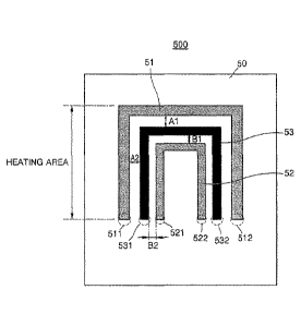
on the third path in the heating area, and the fifth end may be located
between the first end and the
third end in the heating area, and the sixth end may be located between the
second end and the
fourth end in the heating area.
[0009] Also, the non-heating area may include: a first connection portion
connecting the
_)-
CA 03076886 2020-03-24
first end and the third end to the battery; a second connection portion
connecting the second end
and the fourth end to the battery; and a pair of via holes respectively formed
in the fifth end and
the sixth end.
[0010] Also, the first connection portion and the second connection portion
may be
manufactured as an electrically conductive element identical to the first
electrically conductive
heating element and the second electrically conductive heating element, and
may be manufactured
to have a greater width or thickness than the first electrically conductive
heating element and the
second electrically conductive heating element.
[0011] Also, the temperature sensor track may include an electrically
conductive element
having a different thermal coefficient resistance (TCR) or a different
resistance value from the first
electrically conductive heating element and the second electrically conductive
heating element.
[0012] Also, the first electrically conductive heating element and the
second electrically
conductive heating element may have a TCR value between 1200 ppm/ C and 1800
ppin/ C, and
the temperature sensor track may have a TCR value between 3500 ppm/ C and 4100
ppm/ C.
[0013] Also, the first electrically conductive heating element and the
second electrically
conductive heating element may have a resistance value between 0.7 and 0.85 CI
at a room
temperature of 25 C, and the temperature sensor track may have a resistance
value between 12 SI
and 14 C2, at a room temperature of 25 C.
[0014] Also, a distance between the temperature sensor track and the first
electrically .
conductive heating element and a distance between the temperature sensor track
and the second
electrically conductive heating element may be each at least 0.5 mm.
[0015] The heater may be implemented in the form of an internal heater to
be inserted into
-3-
CA 03076886 2020-03-24
the cigarette to heat the cigarette or in the form of an external heater to
heat an outer portion of the
cigarette.
[0016] According to an aspect of the present disclosure, a heater for an
aerosol generating
apparatus for generating aerosol by heating a cigarette, includes: a first
electrically conductive
heating element formed along a first path on an electrically insulating
substrate; a second
electrically conductive heating element formed along a second path on the
electrically insulating
substrate; and a temperature sensor track fowled along a third path in a
region between the first
path and the second path.
ADVANTAGEOUS EFFECTS OF DISCLOSURE
[0017] According to the above description, by arranging a temperature
sensor track in a
region between different electrically conductive heating elements on an
electrically insulating
substrate, the temperature sensor track may sense a temperature in a heating
portion of a heater
uniformly and accurately.
BRIEF DESCRIPTION OF DRAWINGS
[0018] FIGS. 1 through 3 are diagrams showing examples in which a
cigarette is inserted
into an aerosol generating device.
[0019] FIG. 4 illustrates an example of the cigarette.
[0020] FIG. 5 illustrates a planar structure of a heating sheet according
to an exemplary
embodiment.
[0021] FIG. 6 illustrates a detailed view of a planar structure of a
heating sheet according
to an exemplary embodiment.
[0022] FIG. 7 is a cross-sectional view of the planar structure of the
heating sheet of FIG.
-4-
CA 03076886 2020-03-24
6, taken along line X-X and viewed from a side.
[0023] FIGS. 8 and 9 are diagrams illustrating heaters manufactured using
the heating
sheet of FIG. 6.
[0024] FIG. 10 is a diagram for describing simulation results of
temperature sensing
according to different implementation methods of a temperature sensor track.
BEST MODE
[0025] According to an aspect of the present disclosure, an aerosol
generating apparatus
includes: a heater for heating a cigarette accommodated in the aerosol
generating apparatus to
generate aerosol, the heater including a first electrically conductive heating
element formed along
a first path on an electrically insulating substrate, a second electrically
conductive heating element
formed along a second path on the electrically insulating substrate, and a
temperature sensor track
formed along a third path in a region between the first path and the second
path; a battery
configured to supply power to the heater; and a controller configured to
control the power supplied
from the battery to the heater and monitor a temperature sensed using the
temperature sensor track.
[0026] According to another aspect of the present disclosure, a heater for
an aerosol
generating apparatus for generating aerosol by heating a cigarette, includes:
a first electrically
conductive heating element formed along a first path on an electrically
insulating substrate; a
second electrically conductive heating element formed along a second path on
the electrically
insulating substrate; and a temperature sensor track formed along a third path
in a region between
the first path and the second path.
-5-
=
CA 03076886 2020-03-24
MODE OF DISCLOSURE
[0027] With respect to the terms in the various exemplary embodiments, the
general terms
which are currently and widely used are selected in consideration of functions
of structural
elements in the various exemplary embodiments of the present disclosure.
However, meanings of
the terms can be changed according to intention, a judicial precedence, the
appearance of a new
technology, and the like. In addition, in certain cases, a term which is not
commonly used can be
selected. In such a case, the meaning of the term will be described in detail
at the corresponding
portion in the description of the present disclosure. Therefore, the terms
used in the various
exemplary embodiments of the present disclosure should be defined based on the
meanings of the
terms and the descriptions provided herein.
[0028] In addition, unless explicitly described to the contrary, the word
"comprise" and
variations such as "comprises" or -comprising" will be understood to imply the
inclusion of stated
elements but not the exclusion of any other elements. In addition, the terms "-
er", "-or", and
"module" described in the specification mean units for processing at least one
function and
operation and can be implemented by hardware components or software components
and
combinations thereof.
[0029] Hereinafter, example exemplary embodiments of the present disclosure
will be
described in detail with reference to the accompanying drawings. The present
disclosure can,
however, be embodied in many different forms and should not be construed as
limited to the
exemplary embodiments set forth herein.
[0030] Hereinafter, exemplary embodiments of the present disclosure will be
described in
detail with reference to the drawings.
-6-
CA 03076886 2020-03-24
=
[0031] FIGS. 1 through 3 are diagrams showing examples in which a cigarette
is inserted
into an aerosol generating device.
[0032] Referring to FIG. 1, the aerosol generating device 10000 may include
a battery
11000, a controller 12000, and a heater 13000. Referring to FIGS. 2 and 3, the
aerosol generating
device 10000 may further include a vaporizer 14000. Also, the cigarette 20000
may be inserted
into an inner space of the aerosol generating device 10000.
[0033] FIGS. 1 through 3 illustrate components of the aerosol generating
device 10000,
which are related to the present exemplary embodiment. Therefore, it will be
understood by one
of ordinary skill in the art related to the present exemplary embodiment that
other general-purpose
components may be further included in the aerosol generating device 10000, in
addition to the
components illustrated in FIGS. 1 through 3.
[0034] Also, FIGS. 2 and 3 illustrate that the aerosol generating device
10000 includes the
heater 13000. However, according to necessity, the heater 13000 may be
omitted.
[0035] FIG. I illustrates that the battery 11000, the controller 12000, and
the heater 13000
are arranged in series. Also, FIG. 2 illustrates that the battery 11000, the
controller 12000, the
vaporizer 14000, and the heater 13000 are arranged in series. Also, FIG. 3
illustrates that the
vaporizer 14000 and the heater 13000 are arranged in parallel. However, the
internal structure of
the aerosol generating device 10000 is not limited to the structures
illustrated in FIGS. 1 through
3. In other words, according to the design of the aerosol generating device
10000, the battery
11000, the controller 12000, the heater 13000, and the vaporizer 14000 may be
differently
arranged.
[0036] When the cigarette 20000 is inserted into the aerosol generating
device 10000, the
-7-
CA 03076886 2020-03-24
aerosol generating device 10000 may operate the heater 13000 and/or the
vaporizer 14000 to
generate aerosol from the cigarette 20000 and/or the vaporizer 14000. The
aerosol generated by
the heater 13000 and/or the vaporizer 14000 is delivered to a user by passing
through the cigarette
20000.
[0037] According to necessity, even when the cigarette 20000 is not
inserted into the
aerosol generating device 10000, the aerosol generating device 10000 may heat
the heater 13000.
[0038] The battery 11000 may supply power to be used for the aerosol
generating device
10000 to operate. For example, the battery 11000 may supply power to heat the
heater 13000 or
the vaporizer 14000, and may supply power for operating the controller 12000.
Also, the battery
11000 may supply power for operations of a display, a sensor, a motor, etc.
mounted in the aerosol
generating device 10000.
[0039] The controller 12000 may generally control operations of the
aerosol generating
device 10000. In detail, the controller 12000 may control not only operations
of the battery 11000,
the heater 13000, and the vaporizer 14000, but also operations of other
components included in
the aerosol generating device 10000. Also, the controller 12000 may check a
state of each of the
components of the aerosol generating device 10000 to determine whether or not
the aerosol
generating device 10000 is able to operate.
[0040] The controller 12000 may include at least one processor. A
processor can be
implemented as an array of a plurality of logic gates or can be implemented as
a combination of a
general-purpose microprocessor and a memory in which a program executable in
the
microprocessor is stored. It will be understood by One of ordinary skill in
the art that the processor
can be implemented in other forms of hardware.
-8-
CA 03076886 2020-03-24
[0041] The heater 13000 may be heated by the power supplied from
the battery 11000. For
example, when the cigarette 20000 is inserted into the aerosol generating
device 10000, the heater
13000 may be located outside the cigarette 20000. Thus, the heated heater
13000 may increase a
temperature of an aerosol generating material in the cigarette 20000.
[0042] The heater 13000 may include an electro-resistive heater.
For example, the heater
13000 may include an electrically conductive track, and the heater 13000 may
be heated when
currents flow through the electrically conductive track. However, the heater
13000 is not limited
= to the example described above and may include all heaters which may be
heated to a desired
temperature. Here, the desired temperature may be pre-set in the aerosol
generating device 10000
= or may be set as a temperature desired by a user.
[0043] As another example, the heater 13000 may include an
induction heater. In detail,
the heater 13000 may include an electrically conductive coil for heating a
cigarette in an induction
heating method, and the cigarette may include a susceptor which may be heated
by the induction
heater.
[0044] For example, the heater 13000 may include a tube-type
heating element, a plate-
type heating element, a needle-type heating element, or a rod-type heating
element, and may heat
the inside or the outside of the cigarette 20000, according to the shape of
the heating element.
[0045] Also, the aerosol generating device 10000 may include a
plurality of heaters 13000.
Here, the plurality of heaters 13000 may be inserted into the cigarette 20000
or may be arranged
outside the cigarette 20000. Also, some of the plurality of heaters 13000 may
be inserted into the
cigarette 20000 and the others may be arranged outside the cigarette 20000. In
addition, the shape
of the heater 13000 is not limited to the shapes illustrated in FIGS. 1
through 3 and may include
various shapes.
-9-
CA 03076886 2020-03-24
[0046] The vaporizer 14000 may generate aerosol by heating a liquid
composition and the
generated aerosol may pass through the cigarette 20000 to be delivered to a
user. In other words,
the aerosol generated via the vaporizer 14000 may move along an air flow
passage of the aerosol
generating device 10000 and the air flow passage may be configured such that
the aerosol
generated via the vaporizer 14000 passes through the cigarette 20000 to be
delivered to the user.
[0047] For example, the vaporizer 14000 may include a liquid storage, a
liquid delivery
element, and a heating element, but it is not limited thereto. For example,
the liquid storage, the
liquid delivery element, and the heating element may be included in the
aerosol generating device
10000 as independent modules.
[0048] The liquid storage may store a liquid composition. For example, the
liquid
composition may be a liquid including a tobacco-containing material having a
volatile tobacco
flavor component, or a liquid including a non-tobacco material. The liquid
storage may be formed
to be detachable from the vaporizer 14000 or may be formed integrally with the
vaporizer 14000.
[0049] For example, the liquid composition may include water, a solvent,
ethanol, plant
extract, spices, flavorings, or a vitamin mixture. The spices may include
menthol, peppermint,
spearmint oil, and various fruit-flavored ingredients, but are not limited
thereto. The flavorings
may include ingredients capable of providing various flavors or tastes to a
user. Vitamin mixtures
may be a mixture of at least one of vitamin A, vitamin B, vitamin C, and
vitamin E, but are not
limited thereto. Also, the liquid composition may include an aerosol forming
substance, such as
glycerin and propylene glycol.
[0050] The liquid delivery element may deliver the liquid composition of
the liquid storage
to the heating element. For example, the liquid delivery element may be a wick
such as cotton
fiber, ceramic fiber, glass fiber, or porous ceramic, but is not limited
thereto.
-10-
=
CA 03076886 2020-03-24
[0051] The heating element is an element for heating the liquid composition
delivered by
the liquid delivery element. For example, the heating element may be a metal
heating wire, a metal
hot plate, a ceramic heater, or the like, but is not limited thereto. In
addition, the heating element
may include a conductive filament such as nichrome wire and may be positioned
as being wound
around the liquid delivery element. The heating element may be heated by a
current supply and
may transfer heat to the liquid composition in contact with the heating
element, thereby heating
the liquid composition. As a result, aerosol may be generated.
[0052] For example, the vaporizer 14000 may be referred to as a cartomizer
or an atomizer,
but it is not limited thereto.
[0053] The aerosol generating device 10000 may further include general-
purpose
components in addition to the battery 11000, the controller 12000, the heater
13000, and the
vaporizer 14000. For example, the aerosol generating device 10000 may include
a display capable
of outputting visual information and/or a motor for outputting haptie
information. Also, the aerosol
generating device 10000 may include at least one sensor (a puff detecting
sensor, a temperature
detecting sensor, a cigarette insertion detecting sensor, etc.). Also, the
aerosol generating device
10000 may be formed as a structure where, even when the cigarette 20000 is
inserted into the
aerosol generating device 10000, external air may be introduced or internal
air may be discharged.
[0054] Although not illustrated in FIGS. 1 through 3, the aerosol
generating device 10000
and an additional cradle may form together a system. For example, the cradle
may be used to
charge the battery 11000 of the aerosol generating device 10000.
Alternatively, the heater 13000
may be heated when the cradle and the aerosol generating device 10000 are
coupled to each other.
[0055] The cigarette 20000 may be similar to a general combustive
cigarette. For example,
the cigarette 20000 may be divided into a first portion including an aerosol
generating material
-11-
CA 03076886 2020-03-24
=
and a second portion including a filter, etc. Alternatively, the second
portion of the cigarette 20000
may also include an aerosol generating material. For example, an aerosol
generating material made
in the form of granules or capsules may be inserted into the second portion.
[0056] The entire first portion may be inserted into the aerosol
generating device 10000,
and the second portion may be exposed to the outside. Alternatively, a portion
of the first portion
may be inserted into the aerosol generating device 10000. Otherwise, the
entire first portion and a
portion of the second portion may be inserted into the aerosol generating
device 10000. The user
may puff aerosol while holding the second portion by the mouth of the user. In
this case, the aerosol
is generated by the external air passing through the first portion, and the
generated aerosol passes
through the second portion and is delivered to the user's mouth.
[0057] For example, the external air may flow into at least one air
passage formed in the
aerosol generating device 10000. For example, opening and closing of the air
passage and/or a size
of the air passage may be adjusted by the user. Accordingly, the amount of
smoke and smoking
satisfaction may be adjusted by the user. As another example, the external air
may flow into the
cigarette 20000 through at least one hole formed in a surface of the cigarette
20000.
[0058] Hereinafter, an example of the cigarette 20000 will be described
with reference to
FIG. 4.
[0059] FIG. 4 illustrates an example of a cigarette.
=
[0060] Referring to FIG. 4, the cigarette 20000 may include a tobacco rod
21000 and a -
filter rod 22000. The first portion described above with reference to FIGS. 1
through 3 may include
the tobacco rod, and the second portion may include the filter rod 22000.
[0061] FIG. 4 illustrates that the filter rod 22000 includes a single
segment. However, the
-12-
CA 03076886 2020-03-24
filter rod 22000 is not limited thereto. In other words, the filter rod 22000
may include a plurality
of segments. For example, the filter rod 22000 may include a first segment
configured to cool
aerosol and a second segment configured to filter a certain component included
in the aerosol.
Also, as necessary, the filter rod 22000 may further include at least one
segment configured to
perform other functions.
[0062] The cigarette 2000 may be packaged using at least one wrapper
24000. The wrapper =
24000 may have at least one hole through which external air may be introduced
or internal air may
be discharged. For example, the cigarette 20000 may be packaged using one
wrapper 24000. As
another example, the cigarette 20000 may be doubly packaged using at least two
wrappers 24000.
For example, the tobacco rod 21000 may be packaged using a first wrapper, and
the filter rod
22000 may be packaged using a second wrapper. Also, the tobacco rod 21000 and
the filter rod
22000, which are respectively packaged using separate wrappers, may be coupled
to each other,
and the entire cigarette 20000 may be packaged using a third wrapper. When
each of the tobacco
rod 21000 and the filter rod 22000 includes a plurality of segments, each
segment may be packaged
using a separate wrapper. Also, the entire cigarette 20000 including the
plurality of segments,
= which are respectively packaged using the separate wrappers may be
combined and re-packaged
together using another wrapper.
[0063] The tobacco rod 21000 may include an aerosol generating material.
For example,
the aerosol generating material may include at least one of glycerin,
propylene glycol, ethylene
glycol, dipropylene glycol, diethylene glycol, triethylene glycol,
tetraethylene glycol, and oley1
alcohol, but it is not limited thereto. Also, the tobacco rod 21000 may
include other additives, such
as flavors, a wetting agent, and/or organic acid. Also, the tobacco rod 21000
may include a flavored
liquid, such as menthol or a moisturizer, which is injected to the tobacco rod
21000.
-13-
CA 03076886 2020-03-24
[0064] The tobacco rod 21000 may be manufactured in various forms. For
example, the
tobacco rod 21000 may be formed as a sheet or a strand. Also, the tobacco rod
21000 may be
formed as a pipe tobacco, which is formed of tiny bits cut from a tobacco
sheet. Also, the tobacco
rod 21000 may be surrounded by a heat conductive material. For example, the
heat-conducting
material may be, but is not limited to, a metal foil such as aluminum foil.
For example, the heat
conductive material surrounding the tobacco rod 21000 may uniformly distribute
heat transmitted
to the tobacco rod 21000, and thus, the heat conductivity applied to the
tobacco rod may be
increased and taste of the tobacco may be improved. Also, the heat conductive
material
surrounding the tobacco rod 21000 may function as a susceptor heated by the
induction heater.
Here, although not illustrated in the drawings, the tobacco rod 21000 may
further include an
additional susceptor, in addition to the heat conductive material surrounding
the tobacco rod
21000.
[0065] The filter rod 22000 may include a cellulose acetate filter. Shapes
of the filter rod =
22000 are not limited. For example, the filter rod 22000 may include a
cylinder-type rod or a tube-
type rod having a hollow inside. Also, the filter rod 22000 may include a
recess-type rod. When
the filter rod 22000 includes a plurality of segments, at least one of the
plurality of segments may
have a different shape.
[0066] The filter rod 22000 may be formed to generate flavors. For example,
a flavoring
liquid may be injected onto the filter rod 22000, or an additional fiber
coated with a flavoring
liquid may be inserted into the filter rod 22000.
[0067] Also, the filter rod 22000 may include at least one capsule 23000.
Here, the capsule
23000 may generate a flavor or aerosol. For example, the capsule 23000 may
have a configuration
in which a liquid containing a flavoring material is wrapped with a film. For
example, the capsule
-14-
CA 03076886 2020-03-24
23000 may have a spherical or cylindrical shape, but is not limited thereto.
[0068] When the filter rod 22000 includes a segment configured to cool the
aerosol, the
cooling segment may include a polymer material or a biodegradable polymer
material. For
example, the cooling segment may include pure polylactic acid alone, but the
material for forming
the cooling segment is not limited thereto. In some exemplary embodiments, the
cooling segment -
may include a cellulose acetate filter having a plurality of holes. However,
the cooling segment is
not limited to the above-described example and any other cooling segment that
is capable of
cooling the aerosol may be used.
[0069] Although not illustrated in FIG. 4, the cigarette 20000 according
to an exemplary
embodiment may further include a front-end filter. The front-end filter may be
located on a side
of the tobacco rod 21000, which is the side not facing the filter rod 22000.
The front-end filter may
prevent the tobacco rod 21000 from being detached outwards and prevent
liquefied aerosol from
flowing into the aerosol generating device 10000 (FIGS. 1 through 3) from the
tobacco rod 21000,
during smoking.
[0070] Hereinafter, a structure of a heating sheet for manufacturing the
heater 13000 of the
aerosol generating apparatus 10000 of FIGS. 1 through 3 will be described in
detail. Thus,
reference numerals used in FIGS. 1 through 3 may also be used in the
description of the drawings
below.
[0071] FIG. 5 illustrates a planar structure of a heating sheet according
to an exemplary
embodiment.
[0072] As illustrated in FIG. 1, the heater 13000 may be an internal
heater that is
manufactured in a shape of a combination of a cylinder and a cone to be
inserted into the cigarette
-15-
CA 03076886 2020-03-24
20000. Alternatively, the heater 13000 may be an external heater that is
manufactured in a cylinder
form (or a tubular form) as illustrated in FIGS. 2 and 3 to heat an outside of
the cigarette 20000.
FIG. 5 illustrates a planar structure of a heating sheet 500 for manufacturing
the heater 13000
(internal heater or external heater).
[0073] The heater 13000 may be a heater implemented using an electric
resistive element.
=
For example, the heater 13000 may include the heating sheet 500 including an
electric resistive
heating element such as an electrically conductive track. An electric
resistive heating element may
be heated as power is supplied from the battery 11000 and thus a current flows
through the electric
resistive heating element.
[0074] For stable use, the heating sheet 500 of the heater 13000 may be
supplied with
power according to the specifications of 3.2 V, 2.4 A, and 8 W, but the power
is not limited thereto.
When power is supplied to the heating sheet 500 of the heater 13000, the
surface temperature of
the heater 13000 may rise to 400 C or higher. The surface temperature of the
heater 13000 may
rise to about 350 C before 15 seconds after the power supply to the heater
13000 starts. However,
a range of a temperature increase may vary.
[0075] Referring to the planar structure of the heating sheet 500 of the
heater 13000, a first
electrically conductive heating element 51 and a second electrically
conductive heating element
52 which are electrically conductive tracks for heating the cigarette 20000
accommodated in the
aerosol generating apparatus 10000 are formed on an electrically insulating
substrate 50 of the
heating sheet 500. Also, a temperature sensor track 53 for sensing a
temperature of the heater
13000 during heating of the electrically conductive heating elements 51 and 52
is formed thereon.
[0076] The electrically insulating substrate 50 may correspond to a green
sheet formed of
a ceramic synthetic material. Alternatively, the electrically insulating
substrate 50 may be
=
-16-
CA 03076886 2020-03-24
manufactured using paper, glass, ceramic, anodized metal, coated metal or
polyimide. That is, the
electrically insulating substrate 50 may be a substrate manufactured using
various appropriate
= materials.
[0077] The first electrically conductive heating element 51 and
the second electrically
conductive heating element 52 may be manufactured as an electric resistive
heating element and a
heating temperature thereof may be determined according to power consumption
due to resistance
thereof. Resistance values of the first electrically conductive heating
element 51 and the second
electrically conductive heating element 52 may be set based on the power
consumption.
[0078] For example, resistance values of the first electrically
conductive heating element
51 and the second electrically conductive heating element 52 may be in a range
between 0.7 S2 and
0.85 SI at a room temperature of 25 degrees Celsius, but are not limited
thereto. The resistance
values of the first electrically conductive heating element 51 and the second
electrically conductive
heating element 52 may be set variously according to a constituent material,
length, width,
thickness, or pattern or the like of an electric resistive element.
[0079] According to resistance temperature coefficient
characteristics, internal resistance
of the first electrically conductive heating element 51 and the second
electrically conductive
heating element 52 may increase as a temperature increases. For example, in a
certain temperature
range, the resistance of the first electrically conductive heating element 51
and the= second
electrically conductive heating element 52 may be proportional to the
temperature.
[0080] The first electrically conductive heating element 51 and
the second electrically
conductive heating element 52 may be manufactured using tungsten, gold,
platinum, silver, copper,
nickel, palladium, or a combination thereof. In addition, the first
electrically conductive heating
element 51 and the second electrically conductive heating element 52 may be
doped with an
-17-
=
CA 03076886 2020-03-24
appropriate doping material and may include an alloy.
[0081] Referring to FIG. 5, on the electrically insulating substrate 50,
the first electrically
conductive heating element 51 may be formed along a first path at the outer
side of the second
electrically conductive heating element 52. In addition, on the electrically
insulating substrate 50,
the second electrically conductive heating element 52 may be formed along a
second path at the
=
inner side of the first electrically conductive heating element 51. That is,
the planar structure of
the heating sheet 500 according to the present embodiment includes a pair of
electrically
conductive heating elements 51 and 52 formed on the electrically insulating
substrate 50.
[0082] The first electrically conductive heating element 51 and the second
electrically
conductive heating element 52 may be respectively formed on the electrically
insulating substrate
50 on angled paths having an identical pattern and different ratio sizes.
However, the pattern or
shape of the first path and the second path of the first electrically
conductive heating element 51
and the second electrically conductive heating element 52 may be implemented
in various
manners, for example, in a curved form or an irregular shape, instead of an
angled shape.
Furthermore, the pattern or shape of the first path and the second path of the
first electrically
conductive heating element 51 and the second electrically conductive heating
element 52 may be
different from each other. However, even so, the first electrically conductive
heating element 51
on the electrically insulating substrate 50 may preferably have a bigger
pattern or shape than the
second electrically conductive heating element 52 and may preferably be formed
at the outer side
of the second electrically conductive heating element 52.
[0083] On the electrically insulating substrate 50, the temperature sensor
track 53 is formed
along a third path in a region between the first path of the first
electrically conductive heating
element 51 and the second path of the second electrically conductive heating
element 52.
-18-
CA 03076886 2020-03-24
[0084] The temperature sensor track 53 senses a temperature of the heater
13000 heated
by the first electrically conductive heating element 51 and the second
electrically conductive
heating element 52. A structure of a ceramic heater according to the
conventional art includes only
a heating element, and a temperature of the ceramic heater is predicted using,-
a change in a
resistance of the heating element. However, according to the conventional
method described
above, it is difficult to accurately predict an actual temperature of the
heating element. Unlike the
conventional art, the heating sheet 500 of the heater 13000 according to the
present embodiment
includes the temperature sensor track 53 located between the electrically
conductive heating
elements 51 and 52 in a planar structure to uniformly sense a temperature of
the electrically
conductive heating elements 51 and 52, thereby accurately measuring a
temperature of the heater
13000.
[0085] The temperature sensor track 53 may also be manufactured using an
electric
resistive element or an electrically conductive element like the first
electrically conductive heating
element 51 and the second electrically conductive heating element 52. For
example, the
temperature sensor track 53 may be manufactured using "tungsten, gold,
platinum, silver, copper,
nickel, palladium, or a combination thereof, and may be doped with an
appropriate doping material
or may include an alloy.
[0086] Referring to the planar structure of the heating sheet 500, the
first path of the first
electrically conductive heating element 51 is formed at the outer side of the
third path of the
temperature sensor track 53 on the electrically insulating substrate 50, and
the second path of the '
second electrically conductive heating element 52 is formed at the inner side
of the third path of
the temperature sensor track 53 at the electrically insulating substrate 50,
[0087] The temperature sensor track 53 may be an electrically conductive
element having
-19-
CA 03076886 2020-03-24
a different thermal coefficient resistance (TCR) or a different resistance
value from those of the
first electrically conductive heating element 51 and the second electrically
conductive heating
element 52.
[0088] In detail, the first electrically conductive heating element 51 and
the second
electrically conductive heating element 52 may be electrically conductive
elements (or electric
resistive elements) having a TCR value between 1200 ppm/ C and 1800 ppm/ C,
and the
temperature sensor track 53 may be an electrically conductive element (or
electric resistive
element) having a TCR value between 3500 ppm/ C and 4100 ppm/ C. Meanwhile,
the first
electrically conductive heating element 51 and the second electrically
conductive heating element
52 may he electrically conductive elements (or electric resistive elements)
having a resistance
value between 0.7 and 0.85 Q at a room temperature of 25 C, and the
temperature sensor track
53 may be an electrically conductive element (or an electric resistive
element) having a resistance
value between 12 f2 and 14C2 at a room temperature of 25 C.
[0089] The distance Al or A2 between the first electrically conductive
heating element 51
and the temperature sensor track 53 formed on the electrically insulating
substrate 50 may be at
least 0.5 mm. In addition, the distance B1 or B2 between the second
electrically conductive heating
element 52 and the temperature sensor track 53 formed on the electrically
insulating substrate 50
may be at least 0.5 mm. However, the above values are exemplary, and the above-
described
distances may vary according to changes in parameters such as widths,
thicknesses or the like of
the electrically conductive heating elements 51 and 52 and the temperature
sensor track 53.
[0090] Meanwhile, referring to the planar structure of the heating sheet
500, the heating
sheet 500 may be divided into a heating area where the first electrically
conductive heating element
51, the second electrically conductive heating element 52, and the temperature
sensor track 53 are
-20-
CA 03076886 2020-03-24
formed and a non-heating area where ends of the first electrically conductive
heating element 51,
the second electrically conductive heating element 52, and the temperature
sensor track 53 are to
be electrically connected to the battery 11000. However, in FIG. 5, only the
heating area is
illustrated for convenience of description.
[0091] In the heating area, the first electrically conductive heating
element 51 includes a
first end 511 and a second end 512 on the first path. In the heating area, the
second electrically
conductive heating element 52 includes a third end 521 and a fourth end 522 on
the second path.
In the heating area, the temperature sensor track 53 includes a fifth end 531
and a sixth end 532 on
the third path.
[0092] Here, the fifth end 531 of the temperature sensor track 53 is
located between the
first end 511 of the first electrically conductive heating element 51 and the
third end 521 of the
second electrically conductive heating element 52 in the heating area, and the
sixth end 532 of the
temperature sensor track 53 is located between the second end 512 of the first
electrically
conductive heating element 51 and the fourth end 522 of the second
electrically conductive heating
element 52 in the heating area.
[0093] The non-heating area will be described in detail with reference to
FIG. 6.
[0094] FIG. 6 illustrates a detailed view of a planar structure of a
heating sheet according
to an exemplary embodiment.
[0095] Referring to a planar structure of a heating sheet 600 of the
heater 13000 illustrated
in FIG. 6, a heating area and a non-heating area are distinguished. In the
heating area of the heating
sheet 600, as described above with reference to FIG. 5, the first electrically
conductive heating
element 51, the temperature sensor track 53 at the inner side of the first
electrically conductive
-21-
CA 03076886 2020-03-24
heating element 51, and the second electrically conductive heating element 52
at the inner side of
the temperature sensor track 53 are formed.
[0096] The non-heating area of the heating sheet 600 includes a first
connection portion
61 connecting the first end 511 and the third end 521 described with reference
to FIG. 5 to the
battery 11000 and a second connection portion 62 connecting the second end 512
and the fourth
end 522 described with reference to FIG. 5 to the battery 11000. That is, the
first connection portion
61 and the second connection portion 62 correspond to electric coupling
terminals providing
power, which is supplied from the battery 11000, to the first electrically
conductive heating =
element 51 and the second electrically conductive heating element 52.
[0097] Meanwhile, the non-heating area includes a pair of via holes 63 and
64 respectively
formed in the fifth end 531 and the sixth end 532 described with reference to
FIG. 5. The pair of
via holes 63 and 64 are electrically connected to the controller 12000. That
is, as temperature
information sensed by the temperature sensor track 53 is delivered to the
controller 12000 via the
via holes 63 and 64, the controller 12000 may monitor a temperature of the
heater 13000.
[0098] The first connection portion 61 and the second connection portion
62 may be
manufactured using an electrically conductive element (or electric resistive
element) that is
identical to the first electrically conductive heating element 51 and the
second electrically
conductive heating element 52, However, since the first connection portion 61
and the second
connection portion 62 are located in the non-heating area, the first
connection portion 61 and the
second connection portion 62 may preferably be manufactured to have a greater
width or thickness
than the first electrically conductive heating element 51 and the second
electrically conductive
heating element 52 so as to have a lower temperature than the heating area.
[0099] FIG. 7 is a cross-sectional view of the planar structure of the
heating sheet of FIG.
-22-
CA 03076886 2020-03-24
6, taken along line X-X'.
[0100] Referring to FIG. 7, the first electrically conductive heating
element 51, the second
electrically conductive heating element 52, and the temperature sensor track
53 are all formed on
an upper surface of the electrically insulating substrate 50. However, the via
holes 63 and 64 which
electrically connect the temperature sensor track 53 and the controller 12000
may penetrate the
electrically insulating substrate 50.
[0101] FIGS. 8 and 9 are diagrams illustrating heaters manufactured using
the heating
sheet of FIG. 6.
[0102] FIG. 8 illustrates the heater 13000 to implement an internal heater
shape 800 to be
inserted into the cigarette 20000 that is manufactured in the shape of a
combination of a cylinder
and a cone as described with reference to FIG. 1. In detail, the heater 13000
of FIG. 1
corresponding to the internal heater shape 800 may be formed using the heating
sheet 600 of FIG.
6 that is integrally formed with and surrounds a structure 80 having a shape
of a combination of a
cylinder and a cone. Here, the upper surface of the electrically insulating
substrate 50 described
with reference to FIG. 7, that is, a layer on which the electrically
conductive heating elements 51
and 52 and the temperature sensor track 53 are formed, may surround an outer
portion of the
structure 80 to face the outside.
[0103] FIG. 9 illustrates the heater 13000 implemented in an external
heater shape 900 that .. .
heats an outer portion of the cigarette 20000 described with reference to FIG.
2 or FIG. 3. In detail,
the heater 13000 of FIG. 2 or FIG. 3, which correspond to the external heater
shape 900, may be
manufactured by rolling the heating sheet 600 of FIG. 6 into a hollow cylinder
shape or a tubular
shape such that the cigarette 20000 is accommodated in its internal space and
heated. Here, the
upper surface of the electrically insulating substrate 50 described with
reference to FIG. 7, that is,
-23-
CA 03076886 2020-03-24
= a layer on which the electrically conductive heating elements 51 and 52
and the temperature sensor
track 53 are formed, may face the internal space.
[0104] FIG. 10 is a diagram for describing simulation results of
temperature sensing
according to different implementation methods of a temperature sensor track.
[0105] Referring to FIG. 10, in an implementation example 1001, an
electrically
conductive heating element is arranged in an outermost portion, and a
temperature sensor track is
arranged at the inner side of the electrically conductive heating element.
[0106] On the other hand, in an implementation example 1002, as described
above with
reference to FIG. 6 according to the an exemplary embodiment, a first
electrically conductive
heating element is arranged in an outeiinost portion while a temperature
sensor track is arranged .
at the inner side of the first electrically conductive heating element, and a
second electrically
conductive heating element is additionally arranged in an innermost portion of
the temperature
sensor track (M pattern).
[0107] Referring to a temperature sensing result 1000 at a distance
between 4 mm and 7
mm in the heating area, it can be seen that a temperature sensed using the
temperature sensor track
of the implementation example 1001 gradually decreases as the distance
increases. In other words,
a temperature sensed using the temperature sensor track of the implementation
example 1001 is
not uniform at the distance between 4 nun and 7 mm, and thus, it is difficult
to measure an accurate
heater temperature.
[0108] However, it is shown that the temperature sensor track of the
implementation
example 1002 according to the present exemplary embodiment senses a
temperature almost
uniformly at the distance between 4 mm and 7 mm under various temperature
settings such as 325
-24-
CA 03076886 2020-03-24
=
=
C, 320 C, and 315 C. That is, by arranging electrically conductive heating
elements and a
temperature sensor track of the implementation example 1002 according to an
exemplary
embodiment, a temperature in a heating portion of a heater may be sensed
uniformly and
accurately.
[0109] Those of ordinary skill in the art related to the present exemplary
embodiments can
understand that various changes in form and details can be made therein
without departing from
the scope of the characteristics described above. The disclosed methods should
be considered in
descriptive sense only and not for purposes of limitation. Therefore, the
scope of the present
disclosure is defined not by the detailed description of the disclosure but by
the appended claims,
and all differences within the scope will be construed as being included in
the present disclosure.
-25-