Note: Descriptions are shown in the official language in which they were submitted.
1
POINT CLOUD RAIL ASSET DATA EXTRACTION
PRIORITY CLAIM
[0001] The present application claims the priority benefit of U.S. Provisional
Patent Application No. 62/587,760 filed November 17, 2017.
BACKGROUND
[0002] LIDAR (Light Detection and Ranging) surveys are sometimes used to
gather data usable for identifying and mapping objects in a three dimensional
space. Data gathered by way of a LIDAR scan is often referred to as point
cloud
data. LIDAR scanning has significantly reduced the time it takes to gather
data
regarding a three dimensional space. Nonetheless, identifying and mapping
objects such as a guideway, railway or objects associated with the guideway or
railway is a time consuming manual effort that involves extracting the
guideway
or railway, and/or associated objects, locations of the objects, and
attributes
thereof from the point cloud data.
BRIEF DESCRIPTION OF THE DRAWINGS
[0003] Aspects of the present disclosure are best understood from the
following
detailed description when read with the accompanying figures. It is noted
that, in
accordance with the standard practice in the industry, various features are
not
drawn to scale. In fact, the dimensions of the various features may be
arbitrarily
increased or reduced for clarity of discussion.
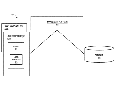
[0004] Figure 1 is a diagram of a system for extracting guideway assets from
point cloud data and generating a map of the guideway and various objects
associated with the guideway, in accordance with one or more embodiments.
[0005] Figure 2 is a diagram of a management platform, in accordance with one
or more embodiments.
[0006] Figure 3 is a flow chart of a method of extracting guideway assets from
point cloud data and generating a map of the guideway and various objects
associated with the guideway, in accordance with one or more embodiments.
[0007] Figure 4 is a flow chart of a method of extracting guideway assets from
point cloud data and generating a map of the guideway and various objects
associated with the guideway, in accordance with one or more embodiments.
Date Recue/Date Received 2021-09-01
CA 03077324 2020-03-26
WO 2019/097486 PCT/IB2018/059071
2
[0008] Figure 5 is a diagram of a user interface, in accordance with one or
more
embodiments.
[0009] Figure 6A is a diagram of a user interface, in accordance with one or
more
embodiments.
[00010] Figure 6B is a diagram of a user interface, in accordance with one or
more
embodiments.
[00011] Figure 7 is a functional block diagram of a computer or processor-
based
system upon which or by which some embodiments are implemented.
DETAILED DESCRIPTION
[00012] The following disclosure provides many different embodiments, or
examples, for implementing different features of the provided subject matter.
Specific examples of components and arrangements are described below to
simplify
the present disclosure. These are, of course, merely examples and are not
intended
to be limiting. For example, the formation or position of a first feature over
or on a
second feature in the description that follows may include embodiments in
which the
first and second features are formed or positioned in direct contact, and may
also
include embodiments in which additional features may be formed or positioned
between the first and second features, such that the first and second features
may not
be in direct contact. In addition, the present disclosure may repeat reference
numerals and/or letters in the various examples. This repetition is for the
purpose of
simplicity and clarity and does not in itself dictate a relationship between
the various
embodiments and/or configurations discussed.
[00013] Further, spatially relative terms, such as "beneath," "below,"
"lower,"
"above," "upper" and the like, may be used herein for ease of description to
describe
one element or feature's relationship to another element(s) or feature(s) as
illustrated
in the figures. The spatially relative terms are intended to encompass
different
orientations of an apparatus, object in use or operation, or objects scanned
in a three
dimensional space, in addition to the orientation thereof depicted in the
figures. The
apparatus may be otherwise oriented (rotated 90 degrees or at other
orientations) and
the spatially relative descriptors used herein may likewise be interpreted
accordingly.
[00014] According to various embodiments, the terms guideway and railway are
used interchangeably for simplicity and ease of discussion. In some
embodiments, a
CA 03077324 2020-03-26
WO 2019/097486 PCT/IB2018/059071
3
guideway is a track, rail, roadway, cable, series of reflectors, series of
signs, a
visible or invisible path, a projected path, a laser-guided path, a global
positioning
system (GPS)-directed path, an object-studded path or other suitable format of
guide, path, track, road or the like on which, over which, below which, beside
which, or along which a vehicle is caused to travel.
[00015] While LIDAR surveys have significantly reduced the time spent on
railways
to gather data usable for mapping the railways, it still takes considerable
time and
manual effort to extract railway assets, locations, and attributes thereof in
a point
cloud generated by a LIDAR scanning of a three dimensional space. It currently
takes days for each hour of scanning to have a user identify railway assets,
identify
and extract railway center lines, identify objects, and then markup and layer
each
railway asset using CAD (Computer Aided Drafting) and/or other software tools
to
gather all of the guideway assets that are often included in a survey.
Although some
software tools are usable for recognizing railway tracks and drawing a center
line
down the tracks so that other railway assets can be measured, these tools are
dependent on significant human-computer interaction to modify CAD lines when
the
software "loses" the rail (for example, is unable to accurately identify the
location of
a rail from the data), are not fully automated, do not process switch areas,
and/or fail
to continue to process new track sections upon a switch area being identified
by a
user.
[00016] Figure 1 is a diagram of a system 100, in accordance with one or more
embodiments In some embodiments, the system 100 makes it possible to
automatically recognize railway assets such as rail tracks, guideway, or
physical
objects associated with the guideway, or other suitable objects by processing
LIDAR
survey point cloud files. In some embodiments, system 100 is configured to
generate an engineering-grade survey from the LIDAR survey point cloud files
that
includes one or more of a map of a guideway, one or more objects associated
with
the guideway, and position data usable to identify a geographical location of
the
guideway or the one or more objects, a location of the guideway or the one or
more
objects with respect to one another, a location of the guideway or the one or
more
objects with respect to a reference position, a location with respect to the
guideway,
or a location of the guideway or the one or more objects with respect to a
reference
plane. In some embodiments, an engineering-grade survey is a survey of a three
CA 03077324 2020-03-26
WO 2019/097486 PCT/IB2018/059071
4
dimensional space that includes locations of landmarks, objects and/or assets
with an
accuracy that is in accordance with a predefined limit associated with a
purpose of
the intended application of the generated survey data. In some embodiments,
the
generated engineer-grade survey yields locations of landmarks/objects/assets
with an
accuracy of +/- 10 cm In some embodiments, the generated engineer-grade survey
yields locations of landmarks/objects/assets with an accuracy of +/- 5 cm. In
some
embodiments, the generated engineer-grade survey yields locations of
landmarks/objects/assets with an accuracy of +/- 15 cm. In some embodiments,
the
generated engineer-grade survey yields locations of landmarks/objects/assets
with an
accuracy of +/- some other suitable allowable deviation.
[00017] As shown in Figure 1, the system 100 comprises user equipment (UE)
101a-
101n (collectively referred to herein as "UE 101") having connectivity to a
management platform 103 and a database 105.
[00018] The UE 101, the management platform 103 and the database 105 are
modular components of a special purpose computer system. In some embodiments,
one or more of the UE 101, the management platform 103, and the database 105
are
unitarily embodied in the UE 101. The UE 101, accordingly, comprises a
processor
by which the management platform 103 is executed. In some embodiments, one or
more of the UE 101, the management platform 103 and/or the database 105 are
configured to be located remotely from each other. By way of example, the UE
101,
the management platform 103 and/or the database 105 communicate by wired or
wireless communication connection and/or one or more networks, or combination
thereof.
[00019] The UE 101 is a type of mobile terminal, fixed terminal, or portable
terminal including a desktop computer, laptop computer, notebook computer,
tablet
computer, wearable circuitry, mobile handset, server, gaming console, or
combination thereof. The UE 101 comprises a display 111 by which a user
interface
113 is displayed. In some embodiments, the user interface 113 additionally or
alternatively comprises an audio interface or an interface that interacts with
a user
via a haptic response.
[00020] Management platform 103 is a set of computer readable instructions
that,
when executed by a processor such as a processor 703 (Figure 7), facilitates
the
connectivity between the UE 101 and database 105. In some embodiments, the
CA 03077324 2020-03-26
WO 2019/097486 PCT/IB2018/059071
management platform 103 causes information that describes one or more of the
UE
101, interactions with user interface 113, or other suitable information to be
stored
in the database 105. In some
embodiments, management platform 103 is
implemented by a computer remote from UE 101. In some
embodiments,
management platform 103 is implemented by one or more UE 101's. In some
embodiments, a portion of management platform 103 is implemented by at least
one
UE 101 and by one or more other UE 101's and/or one or more other computers
remote from UE 101.
[00021] In some embodiments, one or more of management platform 103 or user
interface 113 is associated with a plugin that is installed locally on UE 101.
In some
embodiments, user interface 113 is generated, or at least is caused to output
information associated with generating a guideway map, guideway topology
report,
or other suitable output based on a processing by management platform 103 that
is
one or more of performed locally on UE 101 or remotely from UE 101.
[00022] Database 105 is stored in a memory such as a memory 705 (Figure 7)
capable of being queried or caused to store data associated with the UE 101,
management platform 103, and/or a user interaction with the user interface
113.
[00023] Management platform 103 is configured to cause point cloud data
generated
based on a scanning of a three dimensional space to be displayed by way of
graphical user interface 113. In some
embodiments, the point cloud data is
generated by a LIDAR scanning of the three dimensional space In some
embodiments, management platform 103 is configured to perform a real-time
analysis of point cloud files. In some embodiments, the point cloud data is
included
in files that are .las files, .pts files, or files having some other suitable
format or file
extension.
[00024] In some embodiments, management platform 103 is configured to prompt a
user to set an initialization position within the displayed point cloud data
to start
recognizing a guideway within the point cloud data. In some embodiments,
management platform 103 is configured to place a processing zone having
boundaries at or near the initialization position set by the user. In some
embodiments, management platform 103 prompts a user to place a processing zone
having boundaries within the displayed point cloud data and the placement of
the
processing zone designates the initialization position. In some embodiments,
the
CA 03077324 2020-03-26
WO 2019/097486 PCT/IB2018/059071
6
initialization position is on a boundary of a placed processing zone. In some
embodiments, the initialization position is within the boundaries of the
processing
zone. in some embodiments, the initialization position is a point selected by
way of
a user input and the point selected by way of the user input prompts one or
more of a
beginning of the processing of the point cloud data or the placement of a
processing
zone within the displayed point cloud data In some embodiments, management
platform 103 is configured to automatically establish an initialization
position based
on the displaying of the point cloud data and set a processing zone at or
encompassing the initialization position. In some
embodiments, automatically
establishing the initialization position is based on a pre-established default
position
in a display of point cloud data and a calculation to determine the likelihood
that a
plurality of point cloud data points included in the processing zone as
associated
with a guideway based on a comparison with at least one guideway template
stored
in memory 105. If the comparison results in a likelihood over a predefined
threshold, the management platform 103 defines the points within the
processing
zone as track points. If the comparison results in a likelihood below the
predefined
threshold, the management platform 103 establishes a different initialization
position
in the display of point cloud data that is other than the pre-established
default
position, sets new processing zone based on the different initialization
position,
calculates the likelihood that the plurality of point cloud data points
included in the
processing zone as associated with a guideway based on a comparison with at
least
one guideway template stored in memory 105, and continues to do so until the
comparison results in a likelihood over a predefined threshold, and defines
the points
within the processing zone as track points.
[00025] Management platform 103 detects the initialization position of a
processing
zone within the displayed point cloud data and identifies a plurality of
points within
the processing zone as track points. In some embodiments, the processing zone
has
a predefined direction extending away from the initialization position. In
some
embodiments, the predefined direction of the processing zone is a basis upon
which
an orientation of the processing zone within the displayed point cloud data is
established with respect to the initialization position or some other
reference
position or reference plane. In some
embodiments, the processing zone is
rectangular, cuboid, square, cubic, circular, spherical, elliptical,
trapezoidal,
CA 03077324 2020-03-26
WO 2019/097486 PCT/IB2018/059071
7
triangular, pyramidal, or some other suitable shape. In some embodiments, the
predefined direction of the processing zone is associated with, along,
parallel to,
tangential to, or perpendicular to, a length direction, diametrical direction,
radial
direction, width direction, or other suitable direction correspond to the
shape of the
processing zone. In some embodiments, the size and shape of the processing
zone is
selectable based on a user input. In some embodiments, the size and shape of
the
processing zone is pre-established based on a default setting in management
platform 103.
[00026] In some embodiments, management platform 103 is configured to generate
a
rough model of a guideway in the three dimensional space based on the track
points
and apply a Kalman filter to the rough model of the guideway to identify a
trajectory
of consecutive guideway portions included in the guideway. Management platform
103 is configured to detect a turnout region in the model of the guideway
based on
one or more of the track points, the rough model of the guideway or the
trajectory of
the consecutive guideway portions with one or more turn out templates stored
in
database 105.
[00027] In some embodiments, management platform 103 is configured to generate
an updated model of the guideway by revising the rough model of the guideway
based on the trajectory of the consecutive guideway portions and the turnout
region.
In some embodiments, management platform 103 is configured to detect an object
associated with the guideway based on a comparison of the point cloud data
with one
or more object templates stored in database 105. The one or more object
templates
stored in database 105 are each representative of one or more shapes
associated with
one or more known objects. In some embodiments, the object templates are
representative of one or more of platform bounds, signals, switch areas,
signs,
tunnels, trees, toes, rail types, tongues, or other suitable railway assets or
objects. In
some embodiments, a determination that the point cloud data is associated with
a
known object or a guideway is based on a matching between the point cloud data
and
the templates stored in the database 105 as being within a predefined
percentage
indicative of a likelihood that the point cloud data is associated with one or
more
known objects or a guideway in the three dimensional space. In some
embodiments,
if the comparison results in a percentage match that is greater than 50%, then
management platform 103 determines the point cloud data is associated with a
CA 03077324 2020-03-26
WO 2019/097486 PCT/IB2018/059071
8
matching object or guideway. In some embodiments, management platform 103 is
configured to determine whether the point cloud data is associated with an
object or
a guideway based on some other suitable percentage match. In some embodiments,
if the comparison results in a percentage match that is greater than 90%, then
management platform 103 determines the point cloud data is associated with a
matching object or guideway. In some embodiments, management platform 103 is
configured to determine whether the point cloud data is associated with an
object or
a guideway based on some other suitable percentage match that is specific to a
template, a known object-type, or guideway. In some embodiments, for one type
of
object, if the comparison results in a percentage match that is greater than
50%, then
management platform 103 determines the point cloud data is associated with a
matching object or guideway and for another type of object, if the comparison
results in a percentage match that is greater than 90%, then management
platform
103 determines the point cloud data is associated with a matching object or
guideway.
[00028] Management platform 103 is configured to generate a map comprising the
updated model of the guideway and one or more of the turnout region or the
object,
and at least one label identifying the turnout region or the object included
in the
map.
[00029] In some embodiments, after management platform 103 recognizes a
guideway in the point cloud data, management platform 103 processes the
identified
guideway and "draws" (i.e., establishes or determines and subsequently
displays) a
center line down the guideway. In some embodiments, the guideway is a
monorail, a
dual rail track, a three rail track, or some other suitable quantity of rails
or guides
along which, on which, over which, below which or beside which a vehicle is
capable of traveling. While processing the identified guideway, the management
platform 103 continues along the guideway in a direction away from the
initialization position. In some embodiments, a plurality of processing zones
are
positioned along an estimated guideway. In some embodiments, management
platform 103 generates a plurality of processing zones that are positioned
along an
estimated path of the recognized guideway. In some embodiments, management
platform 103 automatically generates a new processing zone at an end of an
initial
processing zone based on a determination that a guideway exists within the
initial
CA 03077324 2020-03-26
WO 2019/097486 PCT/IB2018/059071
9
processing zone such that the guideway is recognized based on a serial
processing of
a plurality of processing zones, and each processing zone becomes an initial
processing zone upon recognition of a guideway portion therein.
[00030] When the management platform 103 determines that a switch exists in
the
guideway, management platform 103 continues to process the guideway by
proceeding along the right branch of the switch and a new initialization
position is
set on the left branch to be automatically processed later. In some
embodiments,
management platform 103 continues to process the guideway by proceeding along
the left branch of the switch and a new initialization position is set on the
right
branch to be automatically processed later. In some embodiments, management
platform 103 is configured to process each branch of the switch
simultaneously. In
some embodiments, when the management platform 103 determines that a switch
exists in the guideway, management platform 103 continues to process the
guideway
by proceeding along one of the right branch of the switch or the left branch
of the
switch, and sets a new initialization position on the other of the left branch
or the
right branch to be automatically processed in parallel with the processing of
the right
branch of the switch or the left branch of the switch.
[00031] In some embodiments, management platform 103 is configured to initiate
a
user approval process to validate the recognized guideway. In some
embodiments,
upon receiving a user validation of the guideway, management platform 103
processes the point cloud data to identify additional railway assets or
objects
associated with the guideway. In some embodiments, management platform 103
processes the point cloud data to identify one or more of a type of railway
asset or
object or a location of the railway asset or object. In some embodiments, the
location of the railway asset or object is a geographical position, an
identification of
with which track the railway asset or object is associated, an indication of
how far
along the track the railway asset or object is located with respect to a
reference
position, an indication of how far the railway asset or object is located from
the
centerline, or some other suitable positional information. In some
embodiments,
management platform 103 is configured to cause information describing the
railway
asset or object type, position, or other information associated with the
railway asset
or object to be stored in database 105.
CA 03077324 2020-03-26
WO 2019/097486 PCT/1B2018/059071
[00032] In some embodiments, management platform 103 is configured to generate
a
guideway topology report comprising edges and nodes with measurements and
connections. In some embodiments, management platform 103 is configured to
generate computer aided design (CAD) files with rails, centerline(s), and
railway
assets or objects all on separate layers for easy viewing by way of user
interface
113. In some embodiments, management platform 103 is configured to generate a
text export file that lists all railway assets, objects, centerlines, rails,
or other
suitable information for each track, in order as per the measurements along
the track.
In some embodiments, one or more outputs generated by management platform 103
are usable for urban or mainline railway surveys.
[00033] In some embodiments, management platform 103 is configured to build
the
map of the guideway and/or generate the guideway topology to facilitate
extraction
of additional railway assets and identify corresponding unique track and
chainage
(measurement along a track) along with additional parameters such as side of
track,
facing direction, height, or other suitable descriptors in a manner that is
automated
and integrated into the railway survey process to collect attributes for
recognizing
the railway design.
[00034] In some embodiments, management platform 103 automatically recognizes
railway assets or objects such as platform bounds, signals, switch areas,
signs,
tunnels automatically, or other suitable railway assets or objects.
[00035] In some embodiments, system 100 is configured to automate railway and
object recognition in the LIDAR survey process, which makes the procedure
appreciably faster compared to conventional methods of using tape measures and
survey wheels that are prone to human error and are often inaccurate or
unrepeatable. Automatic data extraction from the point cloud data is a
significant
step in applying a LIDAR survey to railway mapping and object recognition.
[00036] Figure 2 is a diagram of a management platform 203, in accordance with
one or more embodiments. In some embodiments, management platform 203 is
usable as management platform 103 (Figure 1). Management platform 203
comprises a guideway detection module 205, an object detection module 207, an
update module 209, a processing module 211, a mapping module 213, a display
module 215 and a communication module 217. In some embodiments, one or more
of the layers or modules included in management platform 203 is at least
partially
CA 03077324 2020-03-26
WO 2019/097486 PCT/IB2018/059071
11
implemented by one or more of a computer remote from UE 101 or another UE 101.
In some embodiments, management platform 203 is entirely implemented by a
processor remote from UE 101. In some embodiments, management platform 203 is
entirely implemented by UE 101.
[00037] In some embodiments, processing module 211 causes point cloud data
received by way of communication module 217 to be processed such that guideway
detection module 205 and object detection module 207 are caused to detect one
or
more guideway portions or one or more objects associated with the guideway
based
on the processing of the point cloud data. In some embodiments, one or more of
guideway detection module 205 or object detection module 207 comprises one or
more algorithms that when applied to the point cloud data, are usable for
identifying
the one or more guideway portions or the one or more objects associated with
the
guideway. Update module 209 is configured to cause one or more of the
algorithms
included in guideway detection module 205 or object detection module 209 to be
modified based on one or more of a user instruction received by way of
communication module 217 or a machine learning algorithm included in update
module 209. Mapping module 213 is configured to generate one or more of a map
of
a three dimensional space based on the processed point cloud data, a map of a
guideway comprising the one or more portions of the guideway based on the
processed point cloud data, or a map of the one or more objects associated
with the
guideway based on the point cloud data. In some embodiments, the one or more
of
the generated one or more maps are combined as layers by mapping module 213 to
be included as an overall system map representing the guideway and the one or
more
objects associated with the guideway in a displayable form to be output by
display
module 215 in a format that is capable of being displayed by way of one or
more of a
graphical user interface, a textual report, or some other suitable format. In
some
embodiments, communication module 217 is configured to cause data to be
received
by management platform 203 for processing, to cause results generated by
management platform 203 to be communicated to an entity external to management
platform 203, or to facilitate communications among the modules included in
management platform 203.
[00038] Figure 3 is a flow chart of a method 300 of extracting guideway assets
from
point cloud data and generating a map of the guideway and various objects
CA 03077324 2020-03-26
WO 2019/097486 PCT/1B2018/059071
12
associated with the guideway, in accordance with one or more embodiments. In
some embodiments, method 300 is performed by at least one processor. In some
embodiments, method 300 is performed by management platform 103 (Figure 1).
[00039] In step 301, point cloud data generated based on a scanning of a three
dimensional space is caused to be displayed by way of a graphical user
interface. In
some embodiments, the point cloud data is generated by a LIDAR scanning of the
three dimensional space.
[00040] In step 303, an initialization position of a processing zone is
detected within
the graphical user interface. The processing zone has boundaries and a
predefined
direction extending away from the initialization position. In some
embodiments, the
processing zone is positioned in the graphical user interface based on a user
input.
In some embodiments, the processing zone is positioned in the graphical user
interface automatically by management platform 103. In some embodiments, the
processing zone comprises a pair of processing windows, the guideway comprises
two rails, and each window of the pair of windows is positioned over one of
the rails
of the pair of rails. In some embodiments, at least one of the processing
windows of
the pair of processing windows has a predefined default shape and size. In
some
embodiments, the processing windows of the pair of processing windows have a
matching shape and size. In some embodiments, at least one processing window
of
the pair of processing windows has a selectable shape and size. In some
embodiments, one processing window of the pair of processing windows has a
shape
and size based on the other processing window included in the pair of
processing
windows. In some embodiments, each processing window is rectangular. In some
embodiments, one or more of the processing windows included in the pair of
processing windows is some other suitable shape.
[00041] In step 305, a plurality of points within the processing zone are
identified as
track points.
[00042] In step 307, a Kalman filter is applied to the track points to
identify a
trajectory of a guideway in the three dimensional space based on the
initialization
position and the predefined direction.
[00043] In step 309, a model of the guideway is generated based on the track
points
and the identified trajectory. In some embodiments, generating the model of
the
guideway comprises processing the track points up to a detected turnout region
or a
CA 03077324 2020-03-26
WO 2019/097486 PCT/1B2018/059071
13
detected object associated with a turnout region, identifying a first branch
of the
guideway and a second branch of the guideway based on the detected turnout
region
or the detected object associated with a turnout region, generating a first
portion of
the model of the guideway based on the track points and the trajectory of one
of the
first branch of the guideway or the second branch of the guideway, and
subsequently
generating a second portion of the model of the guideway based on the track
points
and the trajectory of the other of the first branch of the guideway or the
second
branch of the guideway. In some embodiments, an entirety of the model of the
guideway is generated before detecting one or more objects.
[00044] In step 311, one or more of (1) a turnout region is detected in the
model of
the guideway based on a comparison of the track points with one or more turn
out
templates stored in a database, or (2) an object associated with the guideway
is
detected based on a comparison of the point cloud data with one or more object
templates stored in the database. Each of the one or more turn out templates
is
representative of one or more shapes associated with one or more known turn
out
regions. Each of the one or more object templates is representative of one or
more
shapes associated with one or more known objects. In some embodiments, the
object
associated with the guideway comprises one or more of a platform, a signal, a
sign, a
switch, or a tunnel. In some embodiments, the object associated with the
guideway
comprises one or more ends of a switch track. In some embodiments, an end of a
switch trach is a toe point.
[00045] In some embodiments, one or more of the turnout region or the object
associated with the guideway is detected along the guideway by applying
machine
learning to the point cloud data and the templates to identify the turnout
region or
the object to pattern match possible objects in the point cloud data.
[00046] In step 313, a map is generated. The map comprises the model of the
guideway and one or more of the turnout region or the object, and at least one
label.
In some embodiments, generating the map includes generating multiple layers
comprising a first layer including the model of the guideway and a second
layer
comprising the at least one label. In some embodiments, the first layer and
the
second layer are caused to be displayed simultaneously. In some embodiments,
the
first layer and the second layer are overlapping when displayed
simultaneously. In
some embodiments, the first layer and the second layer are displayed side-by-
side
CA 03077324 2020-03-26
WO 2019/097486 PCT/1B2018/059071
14
when displayed simultaneously. In some embodiments, a selected one of the
first
layer or the second layer is caused to be displayed and a non-selected one of
the first
layer or the second layer is deactivated such that the non-selected layer is
caused to
be hidden from being displayed.
[00047] In some embodiments, step 313 includes drawing a centerline along the
model of the guideway, a distance between the object associated with the
guideway
and the centerline is calculated, a distance between the initialization
position and the
object associated with the guideway along the centerline is calculated, the
calculated
distances are stored in a database, and a guideway topology report is
generated
comprising one or more edges or nodes associated with the object associated
with
the guideway and distances corresponding to each of the one or more edges or
nodes
stored in the database.
[00048] In some embodiments, step 313 includes calculating a height of the
object
associated with the guideway based on the point cloud data, wherein the height
is
determined with respect to one or more of the guideway, a reference position
separate from the guideway, or a predefined reference plane; and including the
height of the object associated with the guideway in one or more of the
guideway
topology report or the map.
[00049] Figure 4 is a flow chart of a method 400 of extracting guideway assets
from
point cloud data and generating a map of the guideway and various objects
associated with the guideway, in accordance with one or more embodiments.
[00050] In some embodiments, method 400 is performed by at least one
processor.
In some embodiments, method 400 is performed by management platform 103
(Figure 1).
[00051] In step 401, point cloud data generated based on a scanning of a three
dimensional space is recognized as input data that is to be processed.
[00052] In step 403, an initialization process is performed that outputs a
rough
model of a guideway included in the three dimensional space.
[00053] In step 405, a track modeling process is performed that outputs an
updated
model of the guideway and one or more turnout regions, objects associated with
the
guideway, track/bed types, or other suitable data is detected and output.
[00054] In step 407, the one or more turnout regions, objects, track/bed types
or
other suitable data is identified and labeled for inclusion in one or more of
a map
CA 03077324 2020-03-26
WO 2019/097486 PCT/1B2018/059071
generated by method 400, a report generated by method 400, or to be stored in
a
database.
[00055] Step 403 includes step 409 in which a track window is positioned
within a
graphical user interface that displays the point cloud data and an
initialization
position of the track window is detected In some embodiments, the track window
has boundaries and a predefined direction extending away from the
initialization
position.
[00056] Step 403 includes step 411 in which a plurality of points within the
track
window are identified as track points. In some embodiments, identifying the
points
within the track window as track points comprises identifying track or track
bed
information indicative of a type of track or track bed with which the track
points are
predicted to be associated. In some embodiments, the type of track or track
bed
indicates that a guideway capable of being modeled based on the point cloud
data is
a monorail, a dual rail, a triple rail, or other suitable quantity of rails or
descriptor
regarding a form of a guideway, a location of the guideway, an indication of
whether
a portion of the guideway within the track window is straight, curved, has an
incline,
decline, or some other suitable descriptor associated with a property of the
guideway.
[00057] Step 403 includes step 413 in which a rough model of a guideway in the
three dimensional space is generated based on the track points. In some
embodiments, the rough model of the guideway is further based on the track or
track
bed information.
[00058] Step 405 includes step 415 in which a Kalman filter is applied to the
rough
model of the guideway to identify a trajectory of consecutive guideway
portions
included in the guideway.
[00059] Step 405 includes step 417 in which the track or track bed information
is
one or more of confirmed or refined based on the trajectory of the consecutive
guideway portions included in the guideway.
[00060] Step 405 includes step 419 in which a turnout region is detected in
the
model of the guideway based on one or more of the track points, the rough
model of
the guideway or the trajectory of the consecutive guideway portions with one
or
more turn out templates stored in a database. In some embodiments, a detected
CA 03077324 2020-03-26
WO 2019/097486 PCT/1B2018/059071
16
turnout region is recognized as being a single track turnout, a double track
turnout,
or some other suitable quantity of track turnout based on the point cloud
data.
[00061] Step 405 includes step 421 in which an updated model of the guideway
is
generated by revising the rough model of the guideway based on the trajectory
of the
consecutive guideway portions and the turnout region
[00062] Step 407 includes step 423 in which one or more of an object
associated
with the guideway is detected based on a comparison of the point cloud data
with
one or more object templates stored in the database, or a type of the turnout
region is
determined based on a comparison of the point cloud data with one or more
turnout
templates stored in the database. In some embodiments, the one or more object
templates are representative of one or more shapes associated with one or more
known objects. In some embodiments, the one or more turnout templates are
representative of one or more shapes associated with one or more known turnout
regions. In some embodiments, a detected turnout region is recognized as being
a
single track turnout, a double track turnout, or some other suitable quantity
of track
turnouts based on the comparison of the point cloud data to the one or more
turnout
templates.
[00063] Step 407 includes step 425 in which a map is generated that comprises
the
updated model of the guideway and one or more of the turnout region or the
object,
stacked, as selectable layers capable of being displayed and/or included in a
system
topology report that includes details describing the guideway, turnout regions
and/or
objects associated with the guideway.
[00064] Step 407 includes step 427 in which at least one of the turnout
regions or
the objects is labeled in one or more of the map or the system topology
report. In
some embodiments, a label describing the turnout region or the object is in a
layer
that includes the turnout region or the object, in a label layer, in a
corresponding
turnout label layer, in a corresponding object label layer, or other suitable
layer
included in the map or the system topology report, or included as part of the
map or
included as a part of the system topology report. In some embodiments, a
generated
label includes an indication of whether a position in the map is a track merge
or
split, a left branch or a right branch of a track, a left side or a right side
of a branch
based on a reference position and a direction away from the reference
position,
CA 03077324 2020-03-26
WO 2019/097486 PCT/1B2018/059071
17
whether an identified object is opened or closed at a time the scan of the
three
dimensional space was performed, or other suitable information.
[00065] Step 407 includes step 429 in which toe points at a turnout region are
identified. In some embodiments, the toe points are objects identified in the
point
cloud data. In some embodiments, the toe points are identified and labeled
separately from the object identification or object labeling
[00066] Figure 5 is a diagram of a user interface 500, in accordance with one
or
more embodiments. User interface 500 is viewable by way of display 111 (Figure
1). User interface 500 is configured to display rail track vectors for a
turnout
region, in accordance with some embodiments.
[00067] User interface 500 is a display of point cloud data 501 that has
several
processing zones 503 that are arranged consecutively over a plurality of areas
included in the point cloud data 501. Turnout regions 505 are highlighted in
user
interface 500. Objects 507 are identified in user interface 500.
[00068] In some embodiments, in order to recognize multi-tracks, a model
selection
process is conducted by applying Minimum Description Length, and turnout
region
505 and its type are recognized using template matching.
[00069] Figures 6A and 6B are diagrams of a user interface 600, in accordance
with
one or more embodiments. User interface 600 is viewable by way of display 111
(Figure 1). User interface 600 is configured to display an image of a relation
between a center of a pair of toes 601 and a switch box 603, in accordance
with
some embodiments.
[00070] Figure 6A includes dimensions indicative of a distance between the
center
of the switch box 603 alongside a guideway 605. The point cloud data shown by
user interface 600 in Figure 6A is based on a reference vantage point and/or
direction in an XYZ axis.
[00071] Figure 6B includes dimensions indicative of the distance between the
center
of the switch box 603 alongside the guideway 605. The point cloud data shown
by
user interface 600 in Figure 6B is based on a different reference vantage
point and/or
direction compared to the reference vantage point or direction in Figure 6A in
the
XYZ axis.
[00072] In some embodiments, because the point cloud data is based on a
scanning
of a three dimensional space, the dimensions between various objects or rail
assets
CA 03077324 2020-03-26
WO 2019/097486 PCT/1B2018/059071
18
may appear different based on the vantage reference point or direction when,
in fact,
the distance is the same. In some embodiments, the capability to rotate,
change, or
otherwise move a view of the point cloud data that is generated by scanning
the
three dimensional space makes it possible to detect additional railway assets
based
on the regularities observed in railway scene by, for example, matching known
device 3D models to possible objects found on or along the guideway. In some
embodiments, a machine learning algorithm is applied to pattern match possible
objects in the point cloud data to templates stored in a database or with user
acknowledged feedback.
[00073] FIG. 7 is a functional block diagram of a computer or processor-based
system 700 upon which or by which an embodiment is implemented.
[00074] Processor-based system 700 is programmed to extract guideway assets
from
point cloud data and generate a map of the guideway and various objects
associated
with the guideway, as described herein, and includes, for example, bus 701,
processor 703, and memory 705 components.
[00075] In some embodiments, the processor-based system is implemented as a
single "system on a chip." Processor-based system 700, or a portion thereof,
constitutes a mechanism for performing one or more steps of extracting
guideway
assets from point cloud data and generating a map of the guideway and various
objects associated with the guideway.
[00076] In some embodiments, the processor-based system 700 includes a
communication mechanism such as bus 701 for transferring information and/or
instructions among the components of the processor-based system 700. Processor
703 is connected to the bus 701 to obtain instructions for execution and
process
information stored in, for example, the memory 705. In some embodiments, the
processor 703 is also accompanied with one or more specialized components to
perform certain processing functions and tasks such as one or more digital
signal
processors (DSP), or one or more application-specific integrated circuits
(ASIC). A
DSP typically is configured to process real-world signals (e.g., sound) in
real time
independently of the processor 703. Similarly, an ASIC is configurable to
perform
specialized functions not easily performed by a more general purpose
processor.
Other specialized components to aid in performing the functions described
herein
CA 03077324 2020-03-26
WO 2019/097486 PCT/1B2018/059071
19
optionally include one or more field programmable gate arrays (FPGA), one or
more
controllers, or one or more other special-purpose computer chips.
[00077] In one or more embodiments, the processor (or multiple processors) 703
performs a set of operations on information as specified by a set of
instructions
stored in memory 705 related to extracting guideway assets from point cloud
data
and generating a map of the guideway and various objects associated with the
guideway. The execution of the instructions causes the processor to perform
specified functions.
[00078] The processor 703 and accompanying components are connected to the
memory 705 via the bus 701. The memory 705 includes one or more of dynamic
memory (e.g., RAM, magnetic disk, writable optical disk, etc.) and static
memory
(e.g., ROM, CD-ROM, etc.) for storing executable instructions that when
executed
perform the steps described herein to extract guideway assets from point cloud
data
and generate a map of the guideway and various objects associated with the
guideway. The memory 705 also stores the data associated with or generated by
the
execution of the steps.
[00079] In one or more embodiments, the memory 705, such as a random access
memory (RAM) or any other dynamic storage device, stores information including
processor instructions for extracting guideway assets from point cloud data
and
generating a map of the guideway and various objects associated with the
guideway.
Dynamic memory allows information stored therein to be changed by system 100.
RAM allows a unit of information stored at a location called a memory address
to be
stored and retrieved independently of information at neighboring addresses.
The
memory 705 is also used by the processor 703 to store temporary values during
execution of processor instructions. In various embodiments, the memory 705 is
a
read only memory (ROM) or any other static storage device coupled to the bus
701
for storing static information, including instructions, that is not changed by
the
system 100. Some
memory is composed of volatile storage that loses the
information stored thereon when power is lost. In some
embodiments, the
memory 705 is a non-volatile (persistent) storage device, such as a magnetic
disk,
optical disk or flash card, for storing information, including instructions,
that
persists even when the system 100 is turned off or otherwise loses power.
CA 03077324 2020-03-26
WO 2019/097486 PCT/IB2018/059071
[00080] The term "computer-readable medium" as used herein refers to any
medium
that participates in providing information to processor 703, including
instructions for
execution. Such a medium takes many forms, including, but not limited to
computer-readable storage medium (e.g., non-volatile media, volatile media).
Non-
volatile media includes, for example, optical or magnetic disks. Volatile
media
include, for example, dynamic memory. Common forms of computer-readable media
include, for example, a floppy disk, a flexible disk, a hard disk, a magnetic
tape,
another magnetic medium, a CD-ROM, CDRW, DVD, another optical medium,
punch cards, paper tape, optical mark sheets, another physical medium with
patterns
of holes or other optically recognizable indicia, a RAM, a PROM, an EPROM, a
FLASH-EPROM, an EEPROM, a flash memory, another memory chip or cartridge,
or another medium from which a computer can read. The term computer-readable
storage medium is used herein to refer to a computer-readable medium.
[00081] An aspect of this description relates to a method that comprises
detecting an
initialization position of a processing zone within a graphical user
interface, the
processing zone having boundaries and a predefined direction extending away
from
the initialization position, the graphical user interface comprising displayed
point
cloud data, the displayed point cloud data being based on a scanning of a
three
dimensional space. The method also comprises identifying a plurality of points
within the processing zone as track points The method further comprises
applying a
Kalman filter to the track points to identify a trajectory of a guideway in
the three
dimensional space based on the initialization position and the predefined
direction.
The method additionally comprises generating a model of the guideway based on
the
track points and the identified trajectory. The method also comprises
detecting one
or more of (1) a turnout region in the model of the guideway based on a
comparison
of the track points with one or more turn out templates stored in a database,
the one
or more turn out templates each being representative of one or more shapes
associated with one or more known turn out regions, or (2) an object
associated with
the guideway based on a comparison of the point cloud data with one or more
object
templates stored in the database, the one or more object templates each being
representative of one or more shapes associated with one or more known
objects.
The method further comprises generating a map comprising the model of the
CA 03077324 2020-03-26
WO 2019/097486 PCT/1B2018/059071
21
guideway and one or more of the turnout region or the object, and at least one
label
identifying the turnout region or the object included in the map.
[00082] Another aspect of this description relates to an apparatus comprising
a
processor and a memory having computer-executable instructions stored thereon
that, when executed by the processor, cause the apparatus to detect an
initialization
position of a processing zone within a graphical user interface, the
processing zone
having boundaries and a predefined direction extending away from the
initialization
position, the graphical user interface comprising displayed point cloud data,
the
displayed point cloud data being based on a scanning of a three dimensional
space.
The apparatus is also caused to identify a plurality of points within the
processing
zone as track points. The apparatus is further caused to apply a Kalman filter
to the
track points to identify a trajectory of a guideway in the three dimensional
space
based on the initialization position and the predefined direction. The
apparatus is
additionally caused to generate a model of the guideway based on the track
points
and the identified trajectory. The apparatus is also caused to detect one or
more of
(1) a turnout region in the model of the guideway based on a comparison of the
track
points with one or more turn out templates stored in a database, the one or
more turn
out templates each being representative of one or more shapes associated with
one or
more known turn out regions, or (2) an object associated with the guideway
based on
a comparison of the point cloud data with one or more object templates stored
in the
database, the one or more object templates each being representative of one or
more
shapes associated with one or more known objects The apparatus is further
caused
to generate a map comprising the model of the guideway and one or more of the
turnout region or the object, and at least one label identifying the turnout
region or
the object included in the map.
[00083] A further aspect of this description relates to a method comprising
detecting
an initialization position of a processing zone within a graphical user
interface, the
processing zone having boundaries and a predefined direction extending away
from
the initialization position, the graphical user interface comprising displayed
point
cloud data, the displayed point cloud data being based on a scanning of a
three
dimensional space. The method also comprises identifying a plurality of points
within the processing zone as track points. The method further comprises
generating
a rough model of a guideway in the three dimensional space based on the track
CA 03077324 2020-03-26
WO 2019/097486 PCT/IB2018/059071
22
points. The method additionally comprises applying a Kalman filter to the
rough
model of the guideway to identify a trajectory of consecutive guideway
portions
included in the guideway. The method also comprises detecting a turnout region
in
the model of the guideway based on one or more of the track points, the rough
model
of the guideway or the trajectory of the consecutive guideway portions with
one or
more turn out templates stored in a database. The method further comprises
generating an updated model of the guideway by revising the rough model of the
guideway based on the trajectory of the consecutive guideway portions and the
turnout region. The method additionally comprises detecting an object
associated
with the guideway based on a comparison of the point cloud data with one or
more
object templates stored in the database, the one or more object templates each
being
representative of one or more shapes associated with one or more known
objects.
The method also comprises generating a map comprising the updated model of the
guideway and one or more of the turnout region or the object, and at least one
label
identifying the turnout region or the object included in the map.
[00084] The foregoing outlines features of several embodiments so that those
skilled
in the art may better understand the aspects of the present disclosure. Those
skilled
in the art should appreciate that they may readily use the present disclosure
as a
basis for designing or modifying other processes and structures for carrying
out the
same purposes and/or achieving the same advantages of the embodiments
introduced
herein Those skilled in the art should also realize that such equivalent
constructions
do not depart from the spirit and scope of the present disclosure, and that
they may
make various changes, substitutions, and alterations herein without departing
from
the spirit and scope of the present disclosure.