Note: Descriptions are shown in the official language in which they were submitted.
ECHOGENIC NERVE BLOCK APPARATUS AND SYSTEM
This application is a divisional of Canadian Patent Application No. 2,811,736
filed on October 17, 2011.
FIELD OF THE INVENTION
This invention relates to pain management systems, and more specifically to
catheter-based infusion systems for the administration of fluids. Most
specifically, this
invention relates to an apparatus and system for performing a nerve block
procedure.
BACKGROUND OF THE INVENTION
Prior to performing a surgical operation on a part of the body, such as for
example the arms or legs, it may be desirable to perform a nerve block in
order to
anesthetize a nerve bundle in a part of the body proximate to where surgery
Will
occur. Often, a catheter-based infusion system is utilized to both block the
nerve
bundle for surgery and to provide a continuous, low flow rate of the
anesthetic over a
period of time (e.g., 2-3 days following surgery) for post-operative pain
management.
One approach is to introduce an epidural-type needle or needle and peel-
away-type sheath into the general area of the desired nerve bundle. Once
proper
location of the needle is achieved, a test dose of the anesthetic may be
provided
through the epidural needle and a catheter may be introduced through the
needle to
administer the anesthetic and maintain the nerve block.
Several methods of targeting needle location exist today ¨ insulated needles
having an integral conductive wire such that a small amount of current may be
pulsed
through the needle or catheter by a nerve stimulator (i.e., a current
generator). An
electrical current of 0.1 to about 2 mA will induce motor movement in the
patient
1
Date Recue/Date Received 2020-04-16
when the tip of the needle (frequently called a "stimulating needle") is near
the nerve.
When the stimulating needle is probed into the general area of the desired
nerve
bundle, the pulsing current stimulates the nerve and causes a motor response
to
assist in properly locating the needle. As the current is reduced, the motor
effect is
also reduced so a needle that causes movement at a low current is likely to be
very
close to the desired area for drug delivery.
One problem with this approach is that the catheter insertion through the
needle may move the tip of the needle away from the target zone. Alternatively
and/or additionally, the tip of the catheter may curl away from the target
zone during
.. insertion.
Several manufacturers have designed stimulating catheters that correct this
problem by passing the current first through the needle and then separately
through
the catheter. The problem with this is that the catheter cannot be steered to
the
target zone without risking pulling back through the needle and potentially
damaging
.. the catheter. In addition, the additional time needle to place and maneuver
the
catheter is significant and after the catheter is secured, it can dislodge by
patient
movement and then become ineffective.
Ultrasound guided techniques have added imaging to the procedure, but they
are mainly used to see the adjacent vessels and are not always good at seeing
the
.. needle and/or catheter. The problem with ultrasound guided techniques is
that the
needle and catheter cannot be easily seen through tissue. That is, the ability
to see
the tip and/or other portions of the needle and/or catheter under ultrasound
imaging
techniques is limited. Another problem is that conventional catheters do not
allow
one to place the catheter quickly allowing for some small migration or tip mis-
.. positioning while still delivering drug to the target area.
A variety of approaches have been used to enhance ultrasonic imaging of
medical devices by increasing the acoustic reflection coefficient of the
devices. In
2
Date Recue/Date Received 2020-04-16
U.S. Patent No. 4,401,124 issued to Guess et al., the reflection coefficient
of a biopsy
needle is enhanced by the use of a diffraction grating disposed on the surface
of the
needle. A variety of mechanisms for enhancing the ultrasound image of a
portion of a
medical instrument are also disclosed in U.S. Patent No. 5,289,831 issued to
Bosley,
U.S. Patent No. 5,201,314 issued to Bosley et al. and U.S. Patent No.
5,081,997,
also issued to Bosley et al. These patents disclose catheters and other
devices
provided with echogenic surfaces including spherical indentations or
projections in
the range of 0.5 to 100 microns or fabricated of material incorporating glass
spheres
or high density metal particles in the range of 0.5 to 100 microns. The use of
micro-
n bubbles introduced into polymers to provide echogenic catheter components
is
described in U. S. Patent No. 5,327,891, issued to Rammler.
However, these features add complexity to manufacturing and may negatively
impact the performance of a catheter having a plurality of exit holes along a
portion of
the catheter. For example, glass beads adhered to the exterior of a catheter
may
become dislodged. Glass beads incorporated into the polymer matrix may create
difficulties during creation of exit holes. Microbubbles formed in the polymer
matrix of
the catheter wall can be difficult to form reliably during the extrusion
process.
Spherical indentations or spherical protuberances can be challenging and/or
expensive to form on a single use item. For example, an EchoTip() Ultrasound
Needle has a plurality of spherical indentations that can increase acoustic
reflection.
However, these spherical indentations can be difficult or expensive to produce
in a
metal needle and may be ineffective when implemented in items that are
generally
not very acoustically reflective such as, for example, a polymer catheter.
SUMMARY OF THE INVENTION
3
Date Recue/Date Received 2020-04-16
The present invention addresses these problems by providing an apparatus
for performing a nerve block procedure, the apparatus being composed of an
echogenic needle and an echogenic catheter configured for controlled delivery
of a
medication.
The present invention also encompasses a system for performing a nerve
block procedure, the system includes introducing an echogenic needle in the
general
area of a nerve bundle, positioning the echogenic needle adjacent the nerve
bundle
utilizing sonic imaging techniques, introducing an echogenic catheter
configured for
controlled delivery of a fluid through the echogenic needle, withdrawing the
echogenic needle, positioning the echogenic catheter adjacent the nerve bundle
utilizing sonic imaging techniques, and delivering fluid to the nerve bundle
through
the echogenic catheter.
An aspect of the present invention encompasses addresses an echogenic
needle configured for placement into the body adjacent a nerve bundle. The
echogenic needle has a distal end composed of an echogenic needle tip, a
hollow
needle body, and a proximal end that includes a fitting. The needle body may
be an
echogenic needle body.
Generally speaking, the echogenic needle tip may be formed from cobalt
chromium (also referred to as "cobalt chrome"), glass or other material having
a high
degree of acoustic impedance. Alternatively and/or additionally, the echogenic
needle tip may have a shape or spatial configuration that reflects an
effective amount
of acoustic waves so the tip is satisfactorily visible during sonic imaging.
Suitable
shapes for the echogenic needle tip include beveled, generally planar
surfaces.
Alternatively and/or additionally, grooves and/or indentations may be added to
the
.. needle.
The needle tip and/or the needle body may be rendered echogenic by coating
the needle tip and/or a surface of the needle body with a material that
increases
4
Date Recue/Date Received 2020-04-16
acoustic impedance. Exemplary materials include titanium carbide, titanium
nitride,
titanium aluminum nitride, titanium aluminum carbon nitride and similar
materials.
Hard, dense, amorphous non-crystalline solids such as glass, acrylic glass ¨
also
referred to as poly(methyl methacrylate), and hard, glassy hydrogels such as
those
.. described in US Patent Application Publication No. US 2006/0141186 may also
be
used. The needle tip and/or needle body may be rendered echogenic by coating
the
needle tip and/or a surface of the needle body with various known echogenic
coatings.
Another aspect of the present invention encompasses an echogenic catheter
configured for controlled delivery of a fluid across an anatomical region. The
echogenic catheter is composed of an elongated tubular member and an echogenic
catheter tip. The elongated tubular member may be an elongated tube with a
plurality
of exit holes or slots in a portion of the elongated tube, and an elongated
porous
member residing within the tube. Alternatively, the elongated tubular member
may be
made of a porous membrane such as a filtration membrane. Exemplary filtration
membranes may be made of polytetrafluoroethylene.
The echogenic catheter tip may be a portion of a distal end of the catheter
formed from cobalt chrome, glass, or other material having a high degree of
acoustic
impedance. Alternatively and/or additionally, the echogenic catheter tip may
be or
may include an echogenic insert or plug formed from or coated with cobalt
chrome,
glass, or other material having a high degree of acoustic impedance. The
echogenic
catheter tip, insert or plug may have a shape or spatial configuration that
reflects an
effective amount of acoustic waves so the tip is satisfactorily visible during
sonic
imaging. Suitable shapes include gear shapes (e.g., circular or cylindrical
shapes
having grooves, notches and/or crenulations that provide a plurality of flat
reflective
surfaces), spherical shapes, multi-faceted geometric shapes formed by
interlocking
polygons (e.g., a geodesic dome shape). Sharp and/or flat edges of the
echogenic
5
Date Recue/Date Received 2020-04-16
insert may engage the walls of the lumen defined by the catheter body to
prevent the
echogenic insert from moving relative to the elongated tubular member.
The elongated tubular member of the catheter (and/or the catheter tip) may be
rendered echogenic by coating an internal or external surface with a material
that
increases its acoustic impedance. Exemplary materials include titanium
carbide,
titanium nitride, titanium aluminum nitride, titanium aluminum carbon nitride
and
similar materials. Hard, dense, amorphous non-crystalline solids such as
glass,
acrylic glass ¨ also referred to as poly(methyl methacrylate, and hard, glassy
hydrogels such as those described in US Patent Application Publication No. US
2006/0141186 may also be used. The elongated tubular member (and/or the
catheter tip) may be rendered echogenic by coating it with various known
echogenic
coatings.
The coating may be on the outside of the elongated tubular member or the
coating may be located on the interior of the elongated tubular member. In
some
aspects of the invention, the coating on the interior of the elongated tubular
member
may be a coating that incorporates acoustically reflective particles in a
carrier. For
example, the coating may include spherical beads of glass or other
acoustically
reflective material in a carrier that binds spherical beads to an internal
surface of the
elongated tubular member.
According to another aspect of the invention, the elongated tubular member of
the catheter may be rendered echogenic by including an internal component that
increases its acoustic impedance. The internal component may be an elongated
tubular coil spring enclosed within the tubular member. The elongated tubular
coil
spring may be may formed from an echogenic material, may be coated with a
material that increases its acoustic impedance, or may have a surface that is
modified with grooves, diffraction gratings, flattened portions, dimples or
the like to
increase its acoustic impedance. Alternatively and/or additionally, the
internal
6
Date Recue/Date Received 2020-04-16
component may be a component that actively generates acoustic waves that are
visible during sonic imaging. Such a component may include an energy source
and a
transducer such as, for example a piezoelectric transducer that converts the
energy
into acoustic waves.
In embodiments where the elongated tubular member is an elongated tube
with a plurality of exit holes or slots in a portion of the elongated tube and
an
elongated porous member resides within the tube, it is contemplated that the
elongated porous member may be made of or may include material that increases
its
acoustic impedance.
Other objects, advantages and applications of the present disclosure will be
made clear by the following detailed description of a preferred embodiment of
the
disclosure and the accompanying drawings wherein reference numerals refer to
like
or equivalent structures.
DESCRIPTION OF THE DRAWINGS
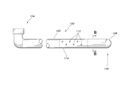
FIG. 1 is an illustration of an exemplary echogenic needle.
FIGS. 2A to 2D are illustrations of illustrated exemplary shapes for
increasing
the acoustic impedance of a needle tip.
FIG. 3 is an illustration of cross-section of the exemplary echogenic needle
of
FIG. 1 taken across line A-A.
FIG. 4 is an illustration of an exemplary echogenic catheter.
FIG. 5 is an illustration of cross-section of the exemplary echogenic catheter
of
FIG. 4 taken across line B-B.
FIG. 6 is an illustration of a detail of an exemplary echogenic catheter
showing
an exemplary echogenic catheter tip.
7
Date Recue/Date Received 2020-04-16
FIG. 7 is an illustration of a detail of an exemplary echogenic catheter
including an exemplary echogenic catheter tip.
FIG. 8 is an illustration of a detail of an exemplary echogenic catheter
showing
an exemplary echogenic insert or plug.
FIG. 9 is an illustration of a cross-section of the exemplary echogenic
catheter
of FIG. 8 taken across line C-C.
FIG. 10 is an illustration of an exemplary echogenic catheter tip.
FIG. 11 is an illustration of a cross-section of an exemplary echogenic
catheter
showing an exemplary echogenic insert or plug.
FIG. 12A is an illustration of an exemplary echogenic catheter tip.
FIG. 12B is an illustration of an exemplary echogenic catheter tip.
FIG. 12C is an illustration of an exemplary echogenic catheter tip.
FIG. 13A is an illustration of an exemplary echogenic catheter showing an
exemplary echogenic insert or plug.
FIG. 13B is an illustration of a cross-section of the exemplary echogenic
catheter of FIG. 13A taken across line D-D.
FIG. 14A is an illustration of an exemplary echogenic catheter incorporating
an
exemplary echogenic bead.
FIG. 14B is an illustration showing a detail of an exemplary echogenic bead
zo from FIG. 14A.
FIG. 15A is an illustration of an exemplary echogenic catheter incorporating
voids or bubbles in the catheter.
8
Date Recue/Date Received 2020-04-16
FIG. 15B is an illustration showing a detail of the echogenic catheter from
FIG.
15A.
FIG. 16A is an illustration of an exemplary echogenic catheter incorporating a
catheter having an elongated shaft.
FIG. 16B is an illustration showing a detail of the echogenic catheter from
FIG.
16A.
FIGS. 17A to 17C are illustrations of an exemplary echogenic catheter
incorporating a spring.
FIG. 18 is an illustration of an exemplary echogenic catheter incorporating a
guide wire.
FIG. 19 is an illustration of an exemplary echogenic catheter incorporating a
metal band.
FIG. 20 is an illustration showing a cross-section of the catheter
incorporating
a metal band from FIG. 19.
DETAILED DESCRIPTION
FIGS. 1-3 illustrate aspects of an exemplary echogenic needle configured for
placement into the body adjacent a nerve bundle. Referring to FIG. 1 the
echogenic
needle 10 has a distal end 12 composed of an echogenic needle tip 14 that may
terminate in a beveled aperture having include beveled, generally planar
surfaces to
zo enhance acoustic impedance. Examples of needles having such surfaces
include,
but are not limited to, PAJUNK needles or QUINCKE needles. The echogenic
needle
10 further has a hollow needle body 16, and a proximal end 18 that may include
a
conventional fitting 20.
9
Date Recue/Date Received 2020-04-16
For example, the echogenic needle may generally have the configuration of a
conventional TUOHY needle except for the echogenic features described herein.
A
suitable needle may be an 18 gauge, steel TUOHY needle with a HUBER tip and a
TUOHY hub. Such TUOHY needles are commercially available, with a non-insulated
tip and a plastic hub as respective integral portions of the needle. Such
TUOHY
needles are available in various lengths. The needle may also be a WEISS
epidural
needle having fixed wings.
Generally speaking, the echogenic needle tip may be formed from or coated
with cobalt chromium (also referred to as "cobalt chrome"), glass or other
material
having a high degree of acoustic impedance. Alternatively and/or additionally,
the
echogenic needle tip may have a shape or spatial configuration that reflects
an
effective amount of acoustic waves so the tip is satisfactorily visible during
sonic
imaging.
Referring now to FIGS. 2A, 2B and 2C, there are illustrated exemplary shapes
for increasing the acoustic impedance of a needle tip. FIG. 2A is a side view
of an
exemplary needle 22 in which a needle body or shaft 24 terminates in a
generally
flat, planar surface 26. An additional planar surface 28 can be seen at the
very tip of
the needle. FIG. 2B is an illustration showing a top view of the needle shown
in FIG.
2A. In this illustration, needle body or shaft 24 terminates in a generally
flat, planar
zo surface 26 which provides surface area to enhance reflection of sonic
energy.
Additional planar surfaces 28 can be seen at the very tip of the needle. The
needle
illustrated in FIGS. 2A and 2B is sometimes referred to as a QUINCKE needle or
a
needle having a QUINCKE-type point. FIG. 2C is an illustration of an exemplary
needle 22 in which a needle body or shaft 24 terminates in a generally flat,
planar
surface 26 which provides surface area to enhance reflection of sonic energy.
The
needle illustrated in FIG. 2C is sometimes referred to as a PAJUNK needle or a
needle having a PAJUNK-type point.
Date Recue/Date Received 2020-04-16
A useful embodiment of a needle is a WEISS epidural needle. In particular,
the needle may be a WEISS epidural needle supplied by Becton Dickinson (BD)
having fixed wings and a modified TUOHY point. The needle may be a five-inch,
18
gauge needle and is identified by the BD product number 405190. It should be
.. appreciated, however, that other types of suitable epidural needles may
also be
utilized.
The needle tip and/or the needle body may be rendered echogenic by coating
the needle tip and/or a surface of the needle body with a material that
increases
acoustic impedance. FIG. 3 illustrates a cross-section of the hollow needle
body 16
taken along line A ¨ A in FIG. 1. As can be seen in FIG. 3, a coating 32 is
applied
over the needle body 34. Generally speaking, the coating can be applied over
only
the needle tip and/or over portions of the needle body (e.g., bands). The
coating
may be applied by mask and dip techniques. The coating thickness may vary
depending on the coating material and its effectiveness at increasing acoustic
.. impedance. For example, the coating may be 1 micrometer in thickness.
Exemplary materials that may be used to coat the needle body 16 include
titanium carbide, titanium nitride, titanium aluminum nitride, titanium
aluminum carbon
nitride, or similar materials may be used. Hard, dense, amorphous non-
crystalline
solids such as glass, acrylic glass ¨ also referred to as poly(methyl
zo methacrylate), and hard, glassy hydrogels such as those described in US
Patent
Application Publication No. US 2006/0141186 published June 29, 2006 by Janssen
et al. for "Gloves With Hydrogel Coating For Damp Hand Donning and Method of
Making Same" may also be used. The needle tip and/or needle body may be
rendered echogenic by coating the needle tip and/or a surface of the needle
body
with various known echogenic coatings such as described in U.S. Patent No.
6,506,156 issued January 14, 2003 to Jones et al. for "Echogenic Coating";
U.S.
Patent No. 7,229,413, issued June 12, 2007 to Violante et al. for "Echogenic
Coatings With Overcoat"; and in U.S. Patent Application Publication No. US
11
Date Recue/Date Received 2020-04-16
2009/0318746 Al, published December 24, 2009 to Thurmond, II et al. for
"Lubricious Echogenic Coatings".
Referring now to FIG. 2D, there is illustrated in perspective view a detail of
an
exemplary needle 22 that is rendered echogenic by joining or incorporating
echogenic elements 29 at or near the very tip of the needle. The needle 22 has
a
needle body or shaft 24 that terminates in a generally flat, planar surface
26. In this
particular example, the needle has a slight curve or bends 27 near the tip of
the
needle that defines the flat planar surface 26. The echogenic elements 29 may
be
glass beads, spherical particles, grooves, indentations or other features that
do not
interfere with the function of the needle. The needle illustrated in FIG. 2D
is
sometimes referred to as a TUOHY needle or a needle having a TUOHY -type
point.
FIGS. 4 -11 illustrate aspects of an exemplary echogenic catheter. While the
catheter may desirably be configured for controlled delivery of a fluid across
an
anatomical region, the catheter may be configured for other purposes.
Generally
speaking, the design of the catheter may be similar to conventional catheters
except
that the catheters are modified to include or incorporate echogenic elements.
Exemplary catheters include those described in U.S. Patent No. 6,350,253
issued
February 26, 2002 to Deniega et al. for "Catheter For Uniform Delivery of
Medication".
Referring now to FIG. 4, the echogenic catheter 100 is composed of an
elongated tubular member 102 having a proximal end 104, a distal end 106 and
an
echogenic catheter tip 108 at its distal end 108. The elongated tubular member
102
may be an elongated tubular member 102 with a plurality of exit holes 112 in
one or
more portions 114 of the elongated tubular member. FIG. 5 illustrates a cross-
section
of the elongated tubular member 102 taken along line B ¨ B in FIG. 4
illustrating a
porous member 116 residing within the tubular member 102. An annular space 118
may be present between the porous member 116 and the elongated tubular member
12
Date Recue/Date Received 2020-04-16
102. Alternatively, the elongated tubular member 102 may be made of a porous
membrane.
The echogenic catheter tip 108 may be a portion of a distal end 106 of the
catheter 100 and may be formed from cobalt chrome, glass, quartz, crystalline
mineral, or other material having a high degree of acoustic impedance. Another
exemplary material may be stainless steel. As shown in FIG. 6, the echogenic
catheter tip 108 may include a support 120. The echogenic catheter tip 108 may
be
formed integrally with the support 120 or may be adhesively bonded thereto.
The
support 120 may optionally be echogenic. Generally speaking, the echogenic
catheter tip 108 may be circular and has a diameter such it is aligned with
the outer
edges of the ribs 122 of the support 120, as shown.
Referring to FIG. 7, there is shown an embodiment in which the echogenic
catheter tip 108 incorporates reflective flakes 130, reflective spheres 132
and/or
reflective particles 136 in a carrier matrix 138 of material such as, for
example,
silicone or other suitable and compatible medical grade plastic that can be
used for
the catheter tip 108. Exemplary reflective flakes 130 include gold flakes,
silver flakes
or the like. Reflective spheres 132 include gold spheres, silver spheres,
glass
spheres or the like. Reflective particles 136 include gold particles, silver
particles,
glass particles or the like.
Alternatively and /or additionally, the echogenic catheter tip 108 can include
a
very dense material incorporated into the carrier matrix at a distal location
to
generate a high degree of impedance mismatch. Dense material could also be
incorporated into the tubular member 102 in a distal location to generate a
high
degree of impedance mismatch.
Appropriate selection of dense materials can create a sufficient level of
difference in the acoustic impedance of the tip 108 and/or portion of the
elongated
tubular member 102 and the acoustic impedance of the surrounding tissue to
create
13
Date Recue/Date Received 2020-04-16
a level of reflection that allows visualization of the tip and/or portion of
the elongated
tubular member 102 utilizing sonic imaging techniques.
One category of relatively dense materials is radio-opaque materials. These
materials may be added to the polymer used to make the catheter or the tip.
Radio-
opaque materials are those that absorb and/or block x-rays from passing
through an
item. These include iodine and barium substances, bismuth salts, tungsten,
gold
metal, halogenated moieties, metal containing, optically transparent polymers
and
mixtures thereof.
Halogenated moieties like halogenated diols and halogenated di-isocyanate
reactants may be used to prepare polyurethane that is radio-opaque and
desirably
visually transparent. It has been found that preparing polyurethane using
trans cyclo-
hexane 1, 4 diisocyanate (t-CHDI) can produce a toxicologically harmless
product
that is radio-opaque yet visibly transparent. More information on this process
may be
found in European Patent Application EP 0 523 928 A2 published January 20,
1993
by Wagener et al. for "Kink Resistant, Flexible, Radiopaque Polyurethane
Tubing and
Catheters Formed Therefrom".
The radio-opaque additive may be present in an amount between 5 and 60
weight percent, more desirably 10 and 40 weight percent or still more
desirably
between 20 and 30 percent. The radio-opaque additive may be compounded with
zo the polymeric material from which the tube is made in the conventional
manner; e.g.,
barium sulfate powder is compounded into the polymer through extrusion
compounding to produce resin pellets at the proper weight percent addition
rate.
It is contemplated that dense materials may be banded or utilized in segments
to provide contrast during sonic imaging. For example, a band or segment may
contain little or no radio-opaque additive and another band or segment may
contain
at least 5 to 10 weight percent more than the section having little or none of
the
additive. It is also contemplated that both types of bands or segments may
contain a
14
Date Recue/Date Received 2020-04-16
radio-opaque material which may be different in type and/or amount, resulting
in a
different degree of density for the bands or segments (e.g. tungsten in one
band or
segment and barium sulfate in another band or segment). This differential in
density
may allow one to discern the locations of the bands or segments utilizing
sonic
imaging because of differences in acoustic impedance.
Alternatively and/or additionally, the echogenic catheter tip may be or may
include an echogenic insert or plug 120 formed from or coated with cobalt
chrome,
glass, quartz, crystalline mineral, or other material having a high degree of
acoustic
impedance. Referring now to FIGS. 8, the echogenic catheter 100 may
incorporate
an echogenic insert or plug 150 having a shape or configuration that reflects
an
effective amount of acoustic waves so the tip or other portion (or portions)
of the
catheter incorporating such an insert is visible during sonic imaging. That
is, the
combination of an appropriate shape or configuration with an echogenic
material or
echogenic coating is thought to greatly enhance the acoustic reflectivity of
the insert
or plug. Suitable shapes include gear shapes (e.g., circular or cylindrical
shapes
having grooves, notches and/or crenulations that provide a plurality of flat
reflective
surfaces), spherical shapes, multi-faceted geometric shapes formed by
interlocking
polygons (e.g., a geodesic shape). FIG. 9 illustrates a cross-section of the
elongated
tubular member 102 taken along line C ¨ C in FIG. 8 illustrating an echogenic
insert
or plug 150 residing within the tubular member 102. As can be seen in FIG. 9,
the
echogenic insert or plug 150 has a "star" shaped cross section defined by
spines 152
extending radially outward from an axial or core region 154 to define a series
of
grooves 156 in the echogenic insert 150.
FIG. 10 illustrates how such a feature may be incorporated in a catheter tip
108 of the type shown in FIG. 6 such that at least a portion of the catheter
tip is
echogenic. That is, the catheter tip, the support or both may be echogenic.
The
catheter tip 108 includes a support 120 that may be formed integrally with the
catheter tip or may be adhesively bonded thereto. The support 120 may be
generally
Date Recue/Date Received 2020-04-16
the same as the illustrated in FIG. 6 except that it is made of or coated with
an
acoustically reflective material and configured to have a shape that is
acoustically
reflective. For example, the support may have geometry similar to the
echogenic
insert illustrated in FIGS. 8 and 9. Referring to FIG. 10, the support 120 has
a "star"
shaped cross section that may be described spines 152 extending radially
outward
from an axial or core region 154 to define a series of grooves 156. In other
words,
the catheter tip may itself be echogenic and/or it may include a support that
is
echogenic.
FIG. 11 illustrates a cross-section of the elongated tubular member 102 taken
along line C ¨ C in FIG. 8 illustrating another exemplary echogenic insert or
plug 150
residing within the tubular member 102. As can be seen in FIG. 11, the
echogenic
insert or plug 150 has a "gear" shaped or crenulated cross section defined by
protuberances 158 extending radially outward from an axial or core region 154
to
define a series of notches 160.
FIG. 12A illustrates another example of such a feature incorporated in a
catheter tip 108 of the type shown in FIG. 6 such that at least a portion of
the
catheter tip is echogenic. The catheter tip 108 includes a support 120 that
may be
formed integrally with the catheter tip or may be adhesively bonded thereto.
In this
example, the support 120 is generally the same as the echogenic insert
illustrated in
FIGS. 11 and has a "gear" shaped or crenulated cross section defined by
protuberances 158 extending radially outward from an axial or core region 154
to
define a series of notches 160.
FIG. 12B illustrates another exemplary catheter tip 108 that includes a
support
120 that may be formed integrally with the catheter tip. The support resides
within
the tubular member 102 and may be secured by adhesive or by a friction fit or
by
other mechanical fastening means. This catheter tip has an "hourglass" shape
and a
surface that is free of crenulations or other complex geometries. FIG. 12C
illustrates
16
Date Recue/Date Received 2020-04-16
another exemplary catheter tip 108 that includes a support 120 that may be
formed
integrally with the catheter tip. The support resides within the tubular
member 102
and may be secured by adhesive or by a friction fit or by other mechanical
fastening
means. This catheter tip has a "bullet" shape and a surface that is free of
crenulations or other complex geometries. These relatively simple shapes are
desirably made of stainless steel but other materials having a high degree of
acoustic
impedance may be used including, but not limited to cobalt chrome, glass, or
quartz.
As generally illustrated in FIGS. 8, 9 and 11, the sharp and/or flat edges of
the
echogenic insert (or support) may engage the walls of the lumen defined by the
elongated tubular member 102 to prevent the echogenic insert (or the echogenic
catheter tip) from moving relative to the elongated tubular member.
Alternatively and with reference to FIG. 13A, the echogenic catheter 100 may
incorporate an echogenic insert or plug 150 within the elongated tubular
member
102. The echogenic insert or plug 150 may be made of glass, quartz crystal or
similar material and has a generally cylindrical shape or configuration and
which
includes one or more tubes or cylindrical channels 170 that passes through the
material to create a density difference that is visible using sonic imaging.
FIG. 13B
is a cross-sectional view of the echogenic catheter shown in FIG. 13A taken
along
line D-D. As illustrated in FIG. 13B, the tubular member 102 incorporates an
zo echogenic insert 150 having a cylindrical cross section and one or more
tubes or
cylindrical channels 170 that passes through the material to create a density
difference that is visible using sonic imaging.
In an aspect of the invention, the echogenic catheter 100 may incorporate an
echogenic bead 172having a spherical or spheroid shape within the elongated
tubular member 102 as illustrated in FIG.14A. The echogenic bead 172 may be
made of glass, quartz crystal or similar material or may be made of any
conventional
non-echogenic material and provided with an echogenic coating. The echogenic
17
Date Recue/Date Received 2020-04-16
bead has a plurality of dimples 174 and may further include rugosities or
wrinkles to
enhance visibility using sonic imaging. FIG. 14B is a perspective view showing
a
detail of the echogenic bead 172 highlighting the dimples and rugosities.
FIG. 15A is a cross-sectional view of an exemplary echogenic catheter 100
illustrating voids or bubbles 176 formed in the elongated tubular member 102.
These
voids or bubbles are generated during manufacture of the catheter. The voids
or
bubbles may be created by introducing a gas into the polymer that is extruded
to form
the catheter. The voids or bubbles may also be created by the extrusion
process, by
mixing a gas generating material with the polymer or by other conventional
techniques. Desirably, the voids or bubbles 176 are present in the material of
the
elongated tubular member 102 as illustrated in FIG. 15B and are not present at
the
surface of the elongated tubular member. It is generally thought that the
voids or
bubbles in the polymer material can provide sufficiently high degree of
impedance
mismatch to allow visualization through sonic imaging. It is contemplated that
materials may be mixed with the polymer to increase the density of the polymer
to
further enhance the degree of impedance mismatch. Exemplary materials are
described above and may include radio-opaque materials.
FIG. 16A is an illustration of an elongated tubular member 102 of an
echogenic catheter 100 incorporating at its distal end 106 an echogenic
catheter tip
zo .. 108 having a shaft 180. The catheter tip 108 may be made echogenic
generally as
described above or it may further include bands 182 of an echogenic material.
It is
contemplated that the bands may be glass, quarts or other echogenic material.
It is
also contemplated that the bands may be a material having a high degree of
impedance mismatch to allow visualization through sonic imaging. FIG. 16B
illustrates a detail of the echogenic catheter tip 108 having a shaft 180 that
incorporates a band or insert 182 of an echogenic material or a material
having a
high degree of impedance mismatch to allow visualization through sonic
imaging.
18
Date Recue/Date Received 2020-04-16
According to an aspect of the invention, the catheter 100 may incorporate a
metal spring 190 within the elongated tubular member 102. Generally speaking,
the
metal spring 190 may be used to provide kink-resistance. The metal spring 190
may
be modified to enhance its acoustic impedance. The can be accomplished by
changing the generally round cross-section 192 of the metal spring 190 as
illustrated
in FIG. 17B into a generally flat cross-section 194 as illustrated in FIG.
17C. This
generally flat cross-section 194 may be provided in portions or alternating
regions of
the metal spring and/or it may be located at the distal end 106 of the
catheter. It is
contemplated that the metal spring 190 may be made actively echogenic by being
connected to a transducer that vibrates the spring at a frequency sufficient
to
generate acoustic waves that are visible through sonic imaging. Such a
transducer
may be, for example a piezoelectric transducer. Other types of transducers may
include magnetostrictive transducers, electromagnetic transducers, or laser-
activated
elements may be used.
The catheter 100 may be made echogenic by incorporating a removable
echogenic guide wire 200 in the catheter. The guide wire 200 may be echogenic
because it is formed it out of an echogenic material or because of an applied
echogenic coating. Alternatively and/or additionally, an echogenic guide wire
tip 202
may be added to the echogenic guide wire 200. It is contemplated that the
guide
zo wire 200 may include a strand or additional wire 204 that is formed it
out of an
echogenic material, contains an applied echogenic coating such that it is
passively
echogenic. The strand or additional wire may be configured to vibrate due to a
connection with a transducer.
Catheters frequently are manufactured with one or more metal band or rings.
In an aspect of the invention, such metal bands or rings may be modified so
they are
echogenic. Referring to FIG. 19, there is shown an illustration of an
exemplary
catheter 100 having a plurality of exit holes 112 and which incorporates a
first metal
band 250 near the distal end 106 of the catheter and a second metal band 252.
19
Date Recue/Date Received 2020-04-16
Referring to FIGS. 19 and 20, the bands may have a cross section that may be
described as defining spines, protuberances, crenels or the like 254 extending
radially outward from the elongated tubular member 102. It should be noted
that the
protuberances 254 are recessed in the catheter so they do not protrude beyond
outermost radial surface of the elongated tubular member 102. Alternatively
and/or
additionally, the metal bands may include grooves, indentations, cross-
hatching or
the like to enhance visualization by sonic imaging techniques.
In an aspect of the invention, the metal band or metal bands and/or any
echogenic component(s) of the catheter may be configured to provide
information
about the catheter. Desirably, that information is provided during sonic
imaging and
is interpreted based on the intensity or placement (or combinations thereof)
of the
echogenic components. In another aspect of the invention, one or more chart(s)
or
other tool(s) may be provided to allow others (e.g., medical professionals) to
interpret
the information. Alternatively and/or additionally, the image provided during
sonic
imaging may be interpreted by the sonic imaging equipment. Examples of
information about the catheter that may be provided include, but are not
limited to,
exit hole placement, exit hole density, length, diameter (or other size
information),
whether the catheter has an open tip, whether the catheter has a closed tip,
and the
like.
The elongated tubular member 102 of the catheter 100 may be rendered
echogenic by coating an internal or external surface with a material that
increases its
acoustic impedance. Exemplary materials include titanium carbide, titanium
nitride,
titanium aluminum nitride, titanium aluminum carbon nitride or similar
materials.
Hard, dense, amorphous non-crystalline solids such as glass, acrylic glass ¨
also
referred to as poly(methyl methacrylate, and hard, glassy hydrogels such as
those
described in US Patent Application Publication No. US 2006/0141186 published
June
29, 2006 by Janssen et al. for "Gloves With Hydrogel Coating For Damp Hand
Donning and Method of Making Same" may also be used.
Date Recue/Date Received 2020-04-16
The coating may be on the outside of the elongated tubular member or the
coating may be located on the interior of the elongated tubular member. In
some
aspects of the invention, the coating on the interior of the elongated tubular
member
may be a coating that incorporates acoustically reflective particles in a
carrier. For
example, the coating may include spherical beads of glass or other
acoustically
reflective material in a carrier that binds spherical beads to an internal
surface of the
elongated tubular member.
Alternatively and/or additionally, the elongated tubular member (and/or the
catheter tip) may be rendered echogenic with various known echogenic coatings
3.0 such as described in U.S. Patent No. 6,506,156 issued January 14, 2003
to Jones et
al.; U.S. Patent No. 7,229,413, issued June 12, 2007 to Violante et al.; and
in U.S.
Patent Application Publication No. US 2009/0318746 Al, published December 24,
2009 to Thurmond, ll et al. According to another aspect of the invention, the
elongated tubular member of the catheter may be rendered echogenic by
including
an internal component that increases its acoustic impedance. The internal
component may be an echogenic metal wire or even an elongated tubular coil
spring
enclosed within the tubular member. The elongated tubular coil spring may be
may
formed from an echogenic material, may be coated with a material that
increases its
acoustic impedance, or may have a surface that is modified with grooves,
diffraction
zo gratings, dimples or the like to increase its acoustic impedance.
Alternatively and/or additionally, the internal component may be a component
that actively generates acoustic waves visible during sonic imaging. Such a
component may include an energy source or may be connected to an energy source
and may further include a transducer such as, for example a piezoelectric
transducer
that converts the energy into acoustic waves. Other types of transducers
including
magnetostrictive transducers, electromagnetic transducers, or laser-activated
elements may be used.
21
Date Recue/Date Received 2020-04-16
In embodiments where the elongated tubular member is an elongated tube
with a plurality of exit holes or slots in a portion of the elongated tube and
an
elongated porous member resides within the tube, it is contemplated that the
elongated porous member may be made of or may include material that increases
its
acoustic impedance. Examples include porous composites that may include
spherical beads of glass or other acoustically reflective material, batts or
webs
formed of thermoplastic polymer fibers having entrapped along the length
thereof
bubbles of a gas, a porous matrix composed of a polymer network having gas
filled
closed cells distributed in the matrix, or similar structures. An example of a
batt or
web formed of thermoplastic polymer fibers having entrapped along the length
thereof bubbles of a gas can be founding U.S. Patent No. 6,395,215 issued May
28,
2002 to Jameson for "Method and Apparatus for Ultrasonically Assisted Melt
Extrusion of Fibers". An example of a porous matrix composed of a polymer
network
having gas filled closed cells distributed in the matrix, or similar
structures can be
found in U.S. Patent No. 7,160,553 issued January 9, 2007 to Gibbins et al.
for
"Matrix for Oxygen Deliver to Compromised Tissues".
The present invention encompasses an apparatus for performing a nerve
block procedure. The apparatus is composed of an echogenic needle as described
above and an echogenic catheter configured for controlled delivery of a
medication
as described above. The apparatus may further include an echogenic sheath.
Exemplary echogenic sheaths are described in U.S. Patent Application
Publication
No. US 2009/0005774 Al, published January 1, 2009 to Fernald. Such an
echogenic
sheath may be rendered echogenic by any of the above described materials or
techniques or combinations thereof. It may, however, be desirable to also
render the
sheath echogenic to aid in the guidance procedure and to ultrasonically verify
placement of the sheath after removal of the needle. In this regard, the
sheath may
contain any manner echogenic material, such as metal threads or flakes, formed
with
the sheath or subsequently added to the surface of the sheath. In another
embodiment, the sheath may be rendered effectively echogenic by simply
defining
22
Date Recue/Date Received 2020-04-16
holes or perforations through the sheath such that that the metal needle is
exposed
through the perforations during the ultrasonically imaging. By detecting axial
points
or sections of the needle through the sheath, the location of the sheath is
also
verified.
The present invention also encompasses a system for performing a nerve
block procedure. The system includes introducing an echogenic needle as
described
above in the general area of a nerve bundle, positioning the echogenic needle
adjacent the nerve bundle utilizing sonic imaging techniques, introducing an
echogenic catheter configured for controlled delivery of a fluid as described
above
through the echogenic needle, withdrawing the echogenic needle, positioning
the
echogenic catheter adjacent the nerve bundle utilizing sonic imaging
techniques, and
delivering fluid to the nerve bundle through the echogenic catheter.
The above-described system for performing a new block procedure may
further include the steps of placing a sheath over the echogenic needle prior
to
introducing the echogenic needle adjacent the general area of the nerve bundle
and
withdrawing the echogenic needle while maintaining the sheath in place and
then
advancing the echogenic catheter through the sheath. The sheath may be an
echogenic as generally described above.
The present invention also encompasses another apparatus for performing a
nerve block procedure. This apparatus includes an echogenic soft tissue
tunneling
device for creating a subcutaneous path for placement of a catheter in a
patient and
an echogenic catheter configured for controlled delivery of a medication.
Exemplary soft tissue tunneling devices are described at, for example, U.S.
Patent Application Publication No. US 2008/0086161 Al for "Soft Tissue
Tunneling
Device" published April 10, 2008 by Massengale et al.; and U.S. Patent
Application
Publication No. US 2008/0312677 Al for "Soft Tissue Tunneling Device"
published
December 18, 2008 by Massengale et al..
23
Date Recue/Date Received 2020-04-16
For example, these soft tissue tunneling devices include an elongate shaft
having a rounded distal end. The distal end and/or the elongate shaft may be
made
echogenic in a manner similar to the echogenic needle and/or catheter as
described
above. These devices may further include a handle secured to the shaft in
which the
.. handle is configured to permit a user of the tunneling device to manually
manipulate
the tunneling device. The elongate shaft may be malleable so as to permit a
shape of
the shaft to be altered prior to use of the tunneling device. For example, the
shaft
may have a non-linear shape including, but not limited to, a curved shape.
The apparatus further includes a sheath positionable over a portion of the
shaft. The sheath has a snug fit with the shaft such that the sheath and the
shaft can
be advanced together and positioned within a body of a patient. According to
the
invention, at least one of the elongate shaft and sheath are echogenic. That
is, the
elongate shaft of the tissue tunneling device may be echogenic, the sheath may
be
echogenic, or both may be echogenic.
According to an aspect of the apparatus for performing a nerve block
procedure, the elongate shaft of the echogenic soft tissue tunneling device
may
define an interior lumen. In addition, the tunneling device may include at
least one
fluid exit opening positioned along the length of the shaft and extending from
the
interior lumen to an external surface of the shaft, and an inlet to the
interior lumen to
permit liquid to be introduced into the interior lumen and administered to the
patient
through the at least one fluid exit opening. The apparatus may further include
a
sheath slidably positioned on the elongate shaft such that at least one of the
elongate
shaft and sheath is echogenic.
In another aspect of the invention, the tunneling device may further include a
retractable needle located at the distal end of the elongate shaft. The
retractable
needle can be used to assist in puncturing the skin prior to advancing the
tunneling
device within the patient's body. The retractable needle can be housed within
the
24
Date Recue/Date Received 2020-04-16
distal end of a needle lumen, and may be fully retracted within the needle
lumen so
that the elongate shaft maintains a substantially blunt distal end. The
position of the
retractable needle within the needle lumen may be changed using any suitable
method.
The present invention also encompasses a system for performing a nerve
block procedure utilizing the echogenic soft tissue tunneling device described
above.
Generally speaking, the system includes the steps of: (i) grasping the handle
of an
echogenic soft tissue tunneling device for creating a subcutaneous path for
placement of a catheter in a patient ¨ in which the tunneling device includes
an
elongate shaft having a rounded distal end and defining at least one interior
lumen
and at least one fluid exit opening in fluid communication with the interior
lumen; (ii)
introducing the echogenic tunneling device into the body of a patient in the
general
area of a nerve bundle; (iii) positioning the echogenic tunneling device
adjacent the
nerve bundle utilizing sonic imaging techniques; (iv) withdrawing the
echogenic
tunneling device; (v) introducing an echogenic catheter configured for
controlled
delivery of a fluid through the subcutaneous path created by the echogenic
tunneling
device; (vi) positioning the echogenic catheter adjacent the nerve bundle
utilizing
sonic imaging techniques, and (vii) delivering fluid to the nerve bundle
through the
echogenic catheter.
In an aspect of the system, the echogenic tunneling device may further include
a sheath that slidably surrounds a portion of the shaft, such that the system
further
includes the steps of (a) introducing and advancing the sheath along with the
introducing and positioning of the tunneling device, and (b) withdrawing the
shaft
from the sheath and leaving the sheath within the body. When such a sheath is
utilized in the system, at least one of the tunneling device and the sheath
should be
echogenic.
Date Recue/Date Received 2020-04-16
While the disclosure has been described in detail with respect to specific
embodiments thereof, it will be apparent to those skilled in the art that
various
alterations, modifications and other changes may be made to the disclosure
without
departing from the scope of the present disclosure. It is therefore intended
that the
claims cover all such modifications, alterations and other changes encompassed
by
the appended claims.
26
Date Recue/Date Received 2020-04-16