Note: Descriptions are shown in the official language in which they were submitted.
TIP PROTECTOR FOR A SAFETY CATHETER
This is a divisional of Canadian Patent Application No. 2,791,402 filed March
17, 2011.
Technical Field
[0001] The present invention relates to safety catheters and, more
particularly, to tip
protectors to shield the sharp tip of the needle cannula used with the
catheter.
Background
[0002] Safety catheters are widely used and typically include a catheter
hub with a
catheter tube extending distally thereof to be placed intravenously, a needle
hub or support -
with a needle cannula extending distally thereof to a sharp distal tip and
extending through
the catheter tube to expose the sharp tip in order to facilitate intravenous
insertion of the
catheter tube, and a tip protector through which at least a portion of the
needle shaft passes
and adapted to enclose or otherwise shield the tip of the needle cannula after
it has been
withdrawn from the catheter tube and into the tip protector.
[0003] One form of tip protector involves a clip that fits within the
catheter hub.
Such clips are readily recognized in that they are thin webs of metal or the
like which are bent
or otherwise formed to have a back wall and one or more distally extending
walls, all
generally of the same thickness. In a ready state of the clip, the needle
shaft of the needle
cannula passes through an aperture in the back wall of the clip and against
the distally
extending arm of the clip, and between the arms where there are two of them,
to pass into the
catheter tube in order to expose the sharp tip. The needle cannula may be
pulled proximally
so as to bring the sharp tip within the clip proximal of the distal end walls
of the arm(s),
whereupon the arms close down to block distal re-emergence of the sharp tip.
Also, a
protuberance or other feature of the needle shaft near the sharp tip is sized
not to readily pass
through the back wall aperture, such that the protuberance engages against the
back wall.
The sharp tip is thus considered protected by the clip, which may be thought
of as the locked
or fired position. Any further proximal movement of the needle cannula will
pull the clip out
from the catheter hub.
[0004] Portions of the clip may be urged radially outwardly into
engagement with an
internal feature of the catheter hub so as to secure the clip within the hub.
In one form, the
presence of the needle against an arm (and between two of them, if present)
urges an aspect
-1-
CA 3078097 2020-04-30
,
of the arm(s) radially outwardly into engagement with a rib or groove of the
catheter hub. In
that form of clip, when the needle tip is pulled into the clip in the fired
position, closing down
of the arms also causes the arm aspect to move radially inwardly and away from
engagement
with the catheter hub, thereby releasing the clip for easy removal from the
catheter hub. That
form of design may be thought of as a passive tip protector, in that the user
need do little
more to remove the clip from the catheter hub than pull the sharp tip into the
clip. In another
form, an aspect of the clip remains urged into engagement with the catheter
hub even in the
fired position, such that removal thereof requires application of a force to
overcome the
engagement, with the force being applied by tugging the needle cannula
proximally to
overcome the force. The latter type of design may be thought of as an active
tip protector in
that the user must apply the added tugging force to overcome the hold of the
clip to the
catheter hub in order to remove the clip.
[0005] Clips have a disadvantage in that they tend to scrape along
the needle shaft as
the needle cannula is pulled proximally from the ready position to the fired
position. That
scraping is objectionable and can be particularly problematic in the passive
tip protector due
to the forces involved in the needle shaft urging the arms radially outwardly
into engagement
with catheter hub. In the active tip protector, the forces involved between
the clip arm(s) and
the needle shaft can be lessened, but at the expense, in part, of requiring
higher removal
forces, which can be objectionable.
[0006] A couple of recent proposals have sought to separate the
catheter hub
engagement function of the clip from the clip protective function so as to
obtain the benefit of
easy removal provided by passive tip protectors with the reduced forces on the
needle shaft
provided by active tip protectors. Those proposals involve an outer member
about the clip,
with the outer member having an engagement portion held radially outwardly
into
engagement with the catheter hub feature by the clip in the ready position. In
those
proposals, a portion of the clip is adjacent the outer member engagement
portion so as to
limit the ability thereof to move radially inwardly and release engagement
with the catheter
hub. When the needle tip is brought into the clip to place the clip in the
fired position, further
proximal movement of the needle cannula pulls the clip proximally relative to
the outer
member to misalign the clip portion from the outer member engagement portion
into a release
position such that the engagement portion can move radially inwardly and out
of engagement
with the catheter hub. These proposals thus involve a clip as an inner member
and an outer
-2-
CA 3078097 2020-04-30
member thereabout, with the two being axially shiftable from the ready and
fired positions to
the release position.
[0007] Those proposals seemingly provide the benefits of reduced needle
shaft and
clip arm forces of the active tip protectors, with the ease of removal of the
passive tip
protectors. But they still have drawbacks and can benefit from improvements.
Summary
[0008] The present invention provides safety catheters with tip
protectors utilizing
axially shiftable members, but which overcome drawbacks of prior proposals and
improve
thereon. To that end, and in accordance with a feature of the present
invention, it is
determined that the prior proposals required that the clip defining the inner
member be
partially within the axial extent of the outer member and partially exposed so
as to be at least
partially within the axial extent of the catheter hub distal of the outer
member. In one aspect
of the present invention, the tip protector has an outer member, with the
engagement portion
defined by one or more flexible tabs thereof which can extend radially
outboard of the body
of the outer member to engage the catheter hub and can move radially inwardly
to release
therefrom, and the inner member is sized and positioned to be completely
within the axial
extent of the outer member. The inner member has a portion to impede radially
inward
movement of the flexible tab when the inner member portion is disposed axially
adjacent the
flexible tab. The inner member is axially shiftable relative to the outer
member between a
first position wherein the distal tip, which may be a sharp tip or a blunt
tip, extends distally of
the tip protector and the inner member portion is disposed axially adjacent
the flexible tabs so
as to impede release of the outer member from the catheter hub, and a second
position
wherein the distal tip is within the outer member and the inner member is
moved such that
the inner member portion is no longer disposed axially adjacent the flexible
tab such that the
inner member no longer impedes release of the outer member from the catheter
hub. In all
positions of the inner and outer members in use, the inner member is retained
completely
within the axial extent of the outer member. The outer member may be in the
form of a
cylindrical body member, with the inner member being a multi-thickness member
that
defines an outer, cylindrical periphery conforming to the interior shape of
the outer member
cylinder.
[0009] In accordance with another feature of the present invention, it is
determined
that the outer member of the prior proposals were generally plastic or other
elastomeric
-3-
CA 3078097 2020-04-30
,
material, and thus are relatively thick. That thickness consumes some of the
valuable cross-
dimensional space of the catheter hub interior, and so limits the cross-
dimension of the clip.
In a further aspect of the invention, the outer member is a thin-walled metal
body, such that
there is more interior space available for the inner member. Further, in
accordance with this
further aspect of the invention, the inner member is advantageously not a
clip, but is instead a
multi-thickness plastic molded component, which can thus take advantage of the
extra
interior space left open by the use of the metal body outer member. The outer
member may
be in the form of a cylindrical body member, with the inner member defining an
outer,
cylindrical periphery conforming to the interior shape of the outer member
cylinder.
[0010] In a particularly advantageous form of the inner plastic
member, the proximal
end thereof is provided with a metal washer to define the back wall aperture.
As a
consequence, a protuberance of the needle cannula engages with metal rather
than plastic, so
as to reduce the risk of deformation of the plastic which might allow the
protuberance thereat
to pass through the back end of the inner member.
[0011] In accordance with a still further feature of the present
invention, the arms of
the inner member may define on confronting faces thereof respective portions
of a tapered
bore, such that as the inner member is moved into the release position, and
the arms come
together, the tapered bore portions cooperate to define a tapered bore, or the
effect of one,
which narrows down to a distal portion of a passageway that is less than the
diameter of the
needle cannula, so as to limit distal re-emergence of the sharp tip therefrom.
In a particularly
advantageous form, the inner member is a multi-thickness plastic molded
component which
facilitates ready formation of the tapered bore portions in each arm thereof.
In some forms,
notably where small diameter needle cannulae are involved, the arms may also
be provided
with confronting ribs distal of the needle tip that mate together in the fired
and/or released
positions to further reduce the likelihood of distal re-emergence of the
needle tip.
[0012] In accordance with yet another feature of the present
invention, clips are
generally prone to what is known as side-out by which the needle cannula may
re-orient in
the fired position so as to project the sharp tip out from between the arms
along the side(s) of
the clip. Some clips have been designed with free-standing wings in an effort
to provide
sidewalls to the clip. In accordance with a yet further aspect of the present
invention, the
confronting face of the arms may be provided with one or more sidebites,
comprising at least
one axially extending projection on the face of one of the arms, and an
axially extending
notch in the face of the other arm. A sidebite interengages when the inner
member is in the
-4-
CA 3078097 2020-04-30
fired (and release) position, so as to reduce the likelihood of lateral offset
of the arms and/or
side-out. In a particularly advantageous form, the inner member is a multi-
thickness plastic
member so as to facilitate formation of the sidebite(s).
[0013] In accordance with still another feature of the present invention,
it is
determined that the inner member can be designed with the arms being normally
urged
radially outwardly, so as to significantly reduce, if not wholly, eliminate
the forces between
the needle shaft and the inner member during movement of the needle cannula
from the ready
state to the fired state. In embodiments having the confronting ribs, the
radially outward bias,
in combination with the radial extent of the ribs, positions the ribs such
that they do not touch
the needle shaft in the ready position, thus further reducing the risk of
forces between the
needle shaft and the inner member.
[0014] By virtue of the foregoing, individually and in combination, there
are thus
provided safety catheters with tip protectors utilizing axially shiftable
members, but which
overcome drawbacks and improve on prior proposals of such tip protectors.
These and other
objects and advantages of the present invention shall be made apparent from
the
accompanying drawings and description thereof.
Brief Description of the Drawings
[0015] The accompanying drawings, which are incorporated in and
constitute a part
of this specification, illustrate embodiments of the invention and, together
with the general
description given above and the detailed description of the embodiments given
below, serve
to explain the principles of the invention.
[0016] Fig. 1 is a disassembled perspective view of a safety catheter in
accordance
with one embodiment of the invention;
[0017] Fig. 2 is an assembled perspective view of the safety catheter
shown in Fig. 1,
but without the protective sheath;
[0018] Fig. 3 is a perspective view of the inner member of the tip
protector in
accordance with one embodiment of the invention;
[0019] Fig. 4 is a cross-sectional view of the inner member shown in Fig.
3 taken
generally along line 4-4 in Fig. 3;
[0020] Fig. 5 is a cross-sectional view of the inner member of the tip
protector taken
generally along line 5-5 in Fig. 3;
-5-
CA 3078097 2020-04-30
[0021] Fig. 6 is a perspective view of the outer member of the tip
protector in
accordance with one embodiment of the invention;
[0022] Fig. 7 is a cross-sectional view of the outer member shown in Fig.
6 taken
generally along line 7-7 in Fig. 6;
[0023] Fig. 8 is a cross-sectional view of the outer member shown in Fig.
6 taken
generally along line 8-8 in Fig. 6;
[0024] Fig. 9 is a partial perspective view of the needle assembly in
accordance with
one embodiment of the invention;
[0025] Fig. 10 is a partial cross-sectional view of the needle assembly
shown in Fig. 9
taken generally along line 10-10 in Fig. 9;
[0026] Fig. 11 is a partial perspective view of the needle cannula
showing an
engaging feature in accordance with one embodiment of the invention;
[0027] Fig. 12 is a cross-sectional view of the needle cannula shown in
Fig. 11 taken
generally along line 12-12 in Fig. 11;
[0028] Fig. 13 is a partial perspective view of the catheter assembly in
accordance
with one embodiment of the invention;
[0029] Fig. 14 is a partial cross-sectional view of the catheter assembly
shown in Fig.
13 taken generally along line 14-14 in Fig. 13;
[0030] Fig. 15 is an enlarged view of the encircled portion shown in Fig.
14;
[0031] Fig. 16A is a partial cross-sectional view of the safety catheter
in the ready
position, wherein the inner member is in a first position relative to the
outer member;
[0032] Fig. 16B is another partial cross-sectional view of the safety
catheter in the
ready position and 90 offset from the view shown in Fig. 16A;
[0033] Fig. 17A is a partial cross-sectional view of the safety catheter
with the distal
tip of the needle cannula disposed in the tip protector;
[0034] Fig. 17B is another partial cross-sectional view of the safety
catheter with the
distal tip of the needle cannula disposed in the tip protector and 90 offset
from the view
shown in Fig. 17A;
[0035] Fig. 18A is a partial cross-sectional view of the safety catheter
in the protected
position, wherein the inner member is in a second position relative to the
outer member;
[0036] Fig. 18B is another partial cross-sectional view of the safety
catheter in the
protected position and 90 offset from the view shown in Fig. 18A;
-6-
CA 3078097 2020-04-30
[0037] Fig. 19 is a partial perspective view of the needle assembly with
the distal tip
of the needle cannula shielded by the tip protector;
[0038] Fig. 20 is a perspective view of an inner member of the tip
protector in an
alternative embodiment in accordance with the invention;
[0039] Fig. 21 is a perspective view of an inner member of the tip
protector in a
further alternative embodiment in accordance with the invention;
[0040] Fig. 22A is a partial cross-sectional view of an alternative
embodiment of a
safety catheter in the ready position, wherein the inner member is in a first
position relative to
the outer member;
[0041] Fig. 22B is another partial cross-sectional view of the safety
catheter of Fig.
22A in the ready position and 90 offset from the view shown in Fig. 22A;
[0042] Fig. 23A is a partial cross-sectional view of the alternative
safety catheter of
Fig. 22A in the protected position, wherein the inner member is in a second
position relative
to the outer member;
[0043] Fig. 23B is another partial cross-sectional view of the safety
catheter of Fig.
23A in the protected position and 90 offset from the view shown in Fig. 23A;
[0044] Fig. 24 is a perspective view of a safety catheter in accordance
with another
embodiment of the invention; and
[0045] Fig. 25 is a perspective view of a safety catheter in accordance
with yet
another embodiment of the invention.
Detailed Description
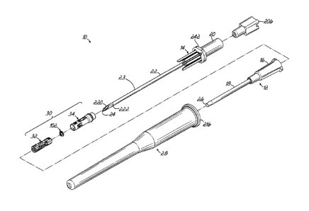
[0046] In reference to Figs. 1 and 2, a peripheral intravenous safety
catheter 10
includes a catheter assembly 12 and a needle assembly 14 nested relative to
the catheter
assembly 12 and configured to provide an interface with the vasculature of a
patient (not
shown). The catheter assembly 12 includes a catheter hub 16 and a generally
flexible
catheter tube 18 coupled to a distal portion of the catheter hub 16 and
extending distally
thereof. The needle assembly 14 includes a needle support or hub 20 and a
needle cannula 22
coupled to a distal portion of the needle hub 20 with a needle shaft 23
extending distally of
the needle hub 20. As is generally conventional, the needle assembly 14 is
positioned
relative to the catheter assembly 12 such that the needle cannula 22 is
disposed within the
catheter tube 18 and a distal tip 24 thereof (which in the embodiment shown is
sharp but
could alternatively be blunt) extends beyond a distal end 26 of the catheter
tube 18 in a ready
-7-
CA 3078097 2020-04-30
,
position of the safety catheter 10, as illustrated in Fig. 2. A sheath 28 may
be provided to
protect the safety catheter 10 prior to use, such as during transit to and
storage in a medical
facility. As will be discussed in more detail below, safety catheter 10
includes an exemplary
tip protector 30 in accordance with various aspects of the present invention
configured to
protect the distal tip 24 of the needle cannula 22 when the needle cannula 22
is withdrawn
from the catheter hub 16 during use.
[0047] As illustrated in Figs. 1 and 19, tip protector 30 is of the
type configured to
enclose the distal portion of the needle cannula 22, including the distal tip
24, while leaving
the more proximal portions of the needle shaft 25 exposed. In accordance with
one aspect of
the invention, the tip protector 30 is a multi-piece design having axially
shiftable members
that cooperate in a manner to provide improved shielding of the distal tip 24
of the needle
cannula 22, and provide improved securement/release of the tip protector 30 to
and from the
catheter hub 16. Additionally, as illustrated in Fig. 2, the tip protector 30
may also be of the
type configured to be positioned substantially within the catheter hub 16, but
as shown herein
advantageously has a relatively small portion extending proximally outside
thereof.
[0048] To this end, the tip protector 30 includes a first, inner
member 32 received
within a second, outer member 34 such that the inner member 32 is axially
shiftable relative
to the outer member 34 between a first position and a second position, as will
be explained in
more detail below. In accordance with one aspect of the invention, the inner
member 32 may
be designed with the primary focus of protecting or shielding the distal tip
24 of the needle
cannula 22. This may be achieved, for example, by blocking the path of the
needle cannula
22 once the inner member 32 has been axially shifted to the second position.
The outer
member 34, on the other hand, may be designed with the primary focus of
securing and
releasing the tip protector 30 to and from the catheter hub 16. While the
particular functions
of the tip protector 30 may be parsed out to, for example, the inner and outer
members 32, 34,
it should be recognized that both members 32, 34 are necessary to provide a
tip protecting
function in the safety catheter 10.
[0049] In one embodiment, and as illustrated in Figs. 3-5, the
inner member 32
includes a generally cylindrical body member 36 having a proximal end 38, a
distal end 40,
and a passageway 42 extending between the proximal and distal ends 38, 40.
Passageway 42
defines a central axis 44 and is configured to receive at least a portion of
the needle cannula
22 therethrough. The cylindrical body member 36 includes a pair of opposed
slots 46 formed
through the wall of the body member 36 to define a pair of opposed arms 48a,
48b capable of
-8-
CA 3078097 2020-04-30
hinging generally inward and outward relative to the central axis 44. In that
regard, the slots
46 intersect the distal end 40 of the body member 36 and extend proximally
therefrom. The
slots 46 have a proximal end 50 that stop short of the proximal end 38 of the
body member 36
to define a generally circumferentially continuous base member 52. To
facilitate hinging of
the arms 48a, 48b, the width of the slots 46 may vary along their length so as
to, for example,
increase in width adjacent to and in a direction toward the proximal end 50 of
the slots 46, as
shown in Figs. 3 and 4, which operates as the hinge or pivot point for arms
48a, 48b.
[0050] In one embodiment, and although not so limited, the arms 48a, 48b
may be
essentially mirror images of each other, and thus a description of one of the
arms (e.g., arm
48a) will suffice as a description of the other arm (arm 48b). Arm 48a
includes an inner
surface 54, an outer surface 56, and a pair of slot faces 58 formed by the
formation of slots 46
in body member 36. The outer surface 56 may be contoured to facilitate
operation of the tip
protector 30. To this end, the outer surface 56 may include a first angled
surface 60 adjacent
each of the slot faces 58 and adjacent the proximal end 50 of the slots 46. A
groove 62 may
also be formed adjacent each of the slot faces 58 and includes a bottom wall
64, a side wall
66, and a proximal end wall 68 (Fig. 3). The groove 62 extends distally from
the first angled
surface 60 toward the distal end 40 of the arm 48a and is open along a distal
end thereof.
Additionally, at least a portion of the distal end 40 of the arm 48a may
include a slight
chamfer 70 formed in the outer surface 56 thereof which leads to a distal end
face 72 of the
arm 48a.
[0051] As shown in Figs. 3 and 4, the outer surface 56 of arm 48a may
include a
raised ridge or boss 74 disposed adjacent the distal end 40 and along an
intermediate portion
of arm 48a (e.g., generally central of the two grooves 62 and, for example,
about ninety
degrees offset relative to slots 46). The raised boss 74 defines abutment
surfaces 76, the
purpose of which is described in more detail below. Moreover, arm 48a may
include a
second groove 78 formed along an intermediate portion of arm 48a (e.g.,
generally aligned
with raised boss 74) that has a proximal end adjacent the proximal end 38 of
body member
36, and a distal end that terminates in arm 48a proximal of raised boss 74.
Groove 78
includes a bottom wall 80, and a pair of opposed side walls 82. The groove 78
may have a
depth that varies along its length and may further have a cavity 84 formed in
the bottom wall
80 thereof. Cavity 84 defines a first end wall 86 and a second end wall 88. In
one
embodiment, the first end wall 86 may generally form an acute or right angle
relative to
bottom wall 80, and the second end wall 88 may generally form an obtuse angle
relative to
-9-
CA 3078097 2020-04-30
,
the bottom wall 80. In addition to the above, the outer surface 56 of the
inner member 32
may include a notch 90 formed adjacent the proximal end 38 and which extends
into (e.g.,
recessed in) the bottom wall 80 of the groove 78.
[0052] The inner surface 54 of the inner member 32 may also be
contoured to
facilitate operation of the tip protector 30. As shown in Figs. 3 and 5, the
inner surface 54 of
arm 48a includes a generally smooth distal tapered bore portion 92. In other
words, the distal
tapered bore portion 92 includes a generally defined radius of curvature that
decreases in the
distal direction (i.e., toward distal end 40). Collectively, the tapered bore
portions 92 of both
arms 48a and 48b define a tapered bore that is a portion of passageway 42
which has a first
cross dimension at a first proximal location and a second cross dimension at a
second distal
location that is less than the first cross dimension, at least when the inner
member 32 is in its
second position relative to outer member 34, as explained in more detail
below.
[0053] In addition to the above, an inner surface 94 of base
member 52 may include
an annular rib 96 that generally defines a proximal facing ledge 98. While the
embodiment
shown in Figs. 3-5 illustrates a single rib that provides a continuous
circumferential ledge, in
alternative embodiments, multiple ribs may be utilized to provide a
discontinuous ledge (not
shown). The ledge 98 generally defines at least in part the boundary of a
proximal cavity 100
configured to receive a needle stop member therein. As discussed in more
detail below, the
stop member may be configured to cooperate with the needle cannula 22 during
its
withdrawal from the catheter assembly 12 so as to effect relative movement
between the
needle cannula 22 and the tip protector 30.
[0054] In an exemplary embodiment, the stop member may include a
stop washer 102
having a distal face 104, a proximal face 106, a side wall 108 extending
between the distal
and proximal faces 102, 104, and a central aperture 110 also extending between
the distal and
proximal faces 102, 104 (Fig. 3). The stop washer 102 is generally
characterized by the
length "1" of the side wall 108 being less than, and preferably significantly
less (such as about
1/5 to 1/7) than a cross-dimension "c" (e.g., diameter or effective diameter)
of the distal and
proximal faces 104, 106. As also illustrated in Fig. 3, in one embodiment, the
stop washer
102 may include at least one leg 112 (one shown) coupled to the side wall 108
and extending
distally thereof. While the stop washer 102 is advantageous in many
applications, other stop
members may be used including, for example, a tubular sleeve. However, a
sleeve is axially
elongated as compared to a washer and may have certain drawbacks that may not
be desirable
in certain applications.
-10-
CA 3078097 2020-04-30
100551 When the stop washer 102 is positioned within proximal cavity 100,
the distal
face 104 thereof is configured to engage the ledge 98 formed by the rib 96.
This engagement
prevents or limits distal movement of the stop washer 102 relative to the
inner member 32.
The stop washer 102 may be captured within cavity 100 by suitable formation of
the
proximal end 38 of the body member 36. To this end, the proximal end 38
includes a
proximal end face 114 having an opening 116 formed therein. The opening 116
has a cross
dimension (e.g., diameter) that is smaller than a cross dimension of the stop
washer 102.
Accordingly, the end face 114 operates to prevent or limit proximal movement
of the stop
washer 102 relative to the inner member 32.
100561 In addition to the above, when the stop washer 102 is disposed
within
proximal cavity 100, the leg 112 is configured to be received within the notch
90 formed
adjacent the proximal end 38 of the body member 36, as illustrated in Fig. 4.
The purpose of
the leg 112 (and thus the notch 90 that receives leg 112) is primarily
directed to facilitating
assembly of the safety catheter 10 through an automated manufacturing process.
The leg 112
and notch 90 otherwise have no role in the proper functioning of the tip
protector 30.
Accordingly, those of ordinary skill in the art will realize that the leg 112
and the notch 90
that receives the leg in an assembled condition may be omitted without
negatively affecting
the operation of the safety catheter 10 depending on the particular
requirements or
preferences of an assembly process.
100571 The body member 36 of inner member 32 may be formed from suitable
materials including various metals and plastics. By way of example, the body
member 36
may be formed from such materials as polypropylene, polyethylene,
polyoxymethylene
(acetal), polycarbonate and nylon. In one aspect, the body member 36 may be
formed from
plastics or other materials suitable for molding processes including, for
example, various
injection molding processes. In an exemplary embodiment, the inner member 32
may be
formed from plastic through a molding process so as to define the multi-
thickness member
shown herein. The stop washer 102 may also be formed from suitable materials
including
various metals and plastics. The stop washer 102 may be generally more rigid
than the body
member 36 and advantageously may be formed from medical grade stainless steel
or other
metals. In this regard, the use of a more rigid material at the location of
engagement between
the needle cannula 22 and the inner member 32 reduces the risk of the plastic
inner member
from deforming and allowing the needle cannula 22 to be pulled from the tip
protector 30.
-11-
CA 3078097 2020-04-30
,
[0058] The stop washer 102 may be assembled with the body member
36 during
manufacturing or during a post-manufacturing process of inner member 32. By
way of
example, the stop washer 102 may be assembled with body member 36 in an over-
molding
process. In that regard, the stop washer 102 may be suitably located within a
mold assembly
as an insert. The mold assembly is then closed and the resin that forms the
body member 36
is injected into the mold so as to form about the insert. In another
embodiment, the body
member 36 may be injection molded without the stop washer 102 being assembled
therewith.
In this method, the proximal end 38 thereof may lack the proximal end face 114
and instead
be formed as an open ended tubular extension of cavity 100 (Fig. 3).
Subsequent to the
molding operation of body member 36, the stop washer 102 may be positioned
within the
cavity 100 and the proximal end 38 processed to form proximal end face 114. By
way of
example, a swaging or other similar process may be utilized to form the
proximal end face
114. Those of ordinary skill in the art may recognize other processes for
manufacturing
and/or assembling the inner member 32 and aspects of the invention are not
limited to those
described herein.
[0059] Turning to the outer member 34 illustrated in Figs. 6-8, in
one embodiment,
the outer member 34 includes a body member 118 which is shown here to be a
thin-walled
generally cylindrical body member 118. Body member 118 has a proximal end 120,
a distal
end 122, and a passageway 124 extending between the proximal and distal ends
120, 122.
The passageway 124 defines a central axis 126 and is configured to receive at
least a portion
of the inner member 32 as well as at least a portion of the needle cannula 22.
When the inner
and outer members 32, 34 are movably coupled in the manner described below,
the central
axes 44, 126 may be configured to be generally colinear. Outer member 34
includes a
number of features that facilitates operation of tip protector 30 through
cooperation with the
inner member 32 as well as with the catheter hub 16.
[0060] In that regard, cylindrical body member 118 includes a pair
of opposed,
generally rectangular openings or cutouts 128 formed through the wall of the
body member
118 adjacent, but spaced from, the distal end 122 thereof In one embodiment,
engagement
portions in the form of at least one generally flexible tab 130 may be
generally disposed in
one or each of the cutouts 128. For example, in one embodiment, two tabs 130
may be
generally disposed in each of the cutouts 128, as shown in Figs. 6 and 7. In
an alternative
embodiment, however, one tab 130 may be generally disposed in each of the
cutouts 128 (not
shown). In a further alternative embodiment, one or two flexible tabs 130 may
be generally
-12-
CA 3078097 2020-04-30
disposed in only one of the cutouts 128. Other combinations may also be
possible. Each of
the flexible tabs 130 has a J-shaped configuration with a proximal end 132
thereof coupled to
a proximal end 134 of a corresponding cutout 128.
[0061] In one embodiment, a distal end 136 of the flexible tabs 130 may
be curved or
hooked in a generally inward direction relative to central axis 126 so as to
define an abutment
surface 138 on an outer surface of the tabs 130 and terminate along a
contacting edge 140
inward of the abutment surface 138 (Fig. 8). While the flexible tabs 130 are
shown as being
curved or hooked in a generally inward direction, in an alternative
embodiment, the flexible
tabs 130 may be curved or hooked in a generally outward direction relative to
central axis
126 such that the contacting edge 140 is directed outwardly (not shown). As
will be
explained in more detail below, the flexible tabs 130 may extend radially
outward of the
cylindrical body member 118 so as to cooperate with the catheter hub 16 and
releasably
secure the tip protector 30 thereto.
[0062] In addition to cutouts 128, the outer member 34 may include at
least one, and
preferably a second pair of opposed, generally rectangular openings or cutouts
142 formed
through the outer wall of the body member 118 adjacent, but spaced from, the
distal end 122
thereof In one embodiment, the cutouts 142 may be about ninety degrees offset
from the
cutouts 128 (e.g., about central axis 126) and may be located slightly
distally of cutouts 128,
although not so limited. Cutouts 142 define a proximal edge 144, a distal edge
146, and a
pair of side edges 148 (Fig. 8). As will be explained in more detail below,
the cutouts 142 are
configured to receive the raised bosses 74 on the inner member 32 when the
safety catheter
is in the ready position.
100631 The outer member 34 may further include at least one, and
preferably a pair of
opposed, generally rectangular indentations 150 formed in the outer wall of
the body member
118. The indentations 150 may be generally axially aligned with cutouts 142
(e.g., about
ninety degrees offset from the cutouts 128) and positioned proximally thereof.
As can be
appreciated, the indentations 150 formed on the outer surface of body member
118 result in
projections relative to the inner surface of the body member 118 that defines
engaging
surfaces 152 that extend away from an inner surface and into the passageway
124 of the outer
member 34. The indentations 150, in effect, define a reduced cross dimension
portion of
passageway 124 and are configured to cooperate with the inner member 32 in a
manner to be
described in more detail below. A hole 154 may be formed in at least one of
the indentations
150. Similar to above, the hole 154 plays no role in the functioning of tip
protector 30.
-13-
CA 3078097 2020-04-30
Instead, hole 154 may facilitate assembly, such as providing a visual aid
during the assembly
process of the catheter device 10. Again, depending on the particular assembly
process, the
hole 154 may be omitted without negatively impacting the operation of tip
protector 30.
[0064] In addition to the above, the outer member 34 may include at least
one, and in
an exemplary embodiment, a pair of opposed slots 156 in body member 118 which
extend in
a generally proximal-distal direction and are generally axially aligned with
the cutouts 142
and indentations 150 of outer member 34. The slots 156, however, may be
positioned
generally proximally of indentations 150. A generally flexible locking tab 158
may be
generally disposed in the at least one slot 156, and preferably in each of the
slots 156. In that
regard, the flexible locking tabs 158 may be coupled to a distal end 160 of
the slots 156 and
extend proximally, but stop short of the proximal end 162 of slots 156. Each
of the flexible
locking tabs 158 may include a distal tab portion 164, a proximal tab portion
166, and an
intermediate tab portion 168. The distal tab portion 164 may be configured to
generally lie
within the slot 156 (e.g., within the perimeter of the outer member 34),
although not so
limited. The intermediate tab portion 168, however, may be generally arcuate
so as to define
an offset between the distal tab portion 164 and the proximal tab portion 166.
In this regard,
the proximal tab portion 166 may be positioned generally inward of distal tab
portion 164
relative to central axis 126 of outer member 34 so as to project into
passageway 124. The
proximal tab portion 166 terminates in a contacting edge 170, the purpose of
which is to be
described in more detail below.
[0065] Adjacent the proximal end 120 of outer member 34 is a generally
outwardly
extending flange 172. In one embodiment, the flange 172 is circumferentially
continuous
(e.g., annular). In an alternative embodiment, the flange 172 may be
circumferentially
discontinuous and define one or more flange portions that project generally
outwardly from
body member 118 (not shown). Flange 172 defines a generally distally-facing
lip 174 and a
generally proximally-facing lip 176. As discussed in more detail below, the
flange 172 may
be configured to cooperate with the catheter hub 16 during use. The flange 172
may also be
configured to cooperate with the needle hub 20, as discussed below. The
proximal end 120
of body member 118 may further include a generally cylindrical extension
portion 178
proximal of the flange 172. The extension portion 178 terminates in a
generally conical
proximal end face 180 having an opening 182 configured to receive at least a
portion of the
needle cannula 22 therethrough. In one embodiment, the proximal end face 180
may be
formed by a plurality of inwardly directed tabs 184 (four shown) that define
the opening 182.
-14-
CA 3078097 2020-04-30
100661 The cylindrical body member 118 of outer member 34 may be formed
from
suitable materials including various metals and plastics. In an advantageous
aspect, the body
member 118 may include a thin-walled cylinder formed from sheet stock metals
capable of
being formed into a generally cylindrical member. Such metals include medical
grade
stainless steels (e.g., 410 stainless steel, 17-7 stainless steel, etc.) with
or without heat
treatment or other processing to achieve a suitable hardness or other desired
characteristics.
In an exemplary embodiment, the outer member 34 may be formed through a
stamping
process of the sheet stock, which stamped material is then put through a
rolling process to
form the outer member 34. The edges of the rolled material may then be joined
through a
suitable process including welding, bonding or other process. In one
embodiment, the edges
may include interlocking features to enhance the securement of the edges to
form the
cylindrical body (e.g., a zipper configuration). Those of ordinary skill in
the art may
recognize other processes for forming outer member 34 or for coupling the
edges to form a
generally cylindrical shape. In contrast to previous designs, the outer member
34 has a thin-
walled (but sufficiently strong) design that provides increased space for the
inner member
(e.g., bulkier, plastic inner member).
100671 As described above, the needle assembly 14 generally includes
needle hub 20
and needle cannula 22 coupled to a distal portion of needle hub 20 with a
needle shaft 23
extending distally thereof. As shown in more detail in Figs. 9 and 10, the
needle hub 20 may
include a generally cylindrical body member 186 having a distal nose 188, a
proximal tubular
portion 190, and a generally outwardly extending intermediate flange 192
disposed
therebetween. The distal nose 188 may be configured to receive therein and
secure thereto a
proximal portion of the needle cannula 22. The distal nose 188 may further
include a
plurality of circumferentially spaced spines 194 (four shown) that extend in a
generally
proximal-distal direction therealong. The spines 194 provide increased
strength to the needle
hub 20 and may further facilitate assembly of the safety catheter 10. At least
one, and
preferably each of the spines 194 extends beyond a distal end 196 of nose 188
to define an
inner surface 198 and a generally distally-directed end face 200.
Additionally, a distal end of
inner surface 198 may include a taper or bevel 202.
100681 The proximal tubular portion 190 defines an interior chamber 204
that is in
fluid communication with a lumen of the needle cannula 22 such that the
chamber 204 may
operate as a flash chamber for the safety catheter 10, as is generally known
in the art. A flash
plug 206 closes off the chamber 204 and is configured to allow gases to pass
therethrough
-15-
CA 3078097 2020-04-30
while retaining liquid, such as blood and other bodily fluids, within chamber
204. In one
embodiment, an outer surface 208 of the proximal tubular portion 190 is
generally smooth.
In an alternative embodiment, however, the outer surface 208 may include grip-
enhancement
features, such as various depressions or projections that facilitate gripping
of the needle hub
20 by a user (not shown). In such a case, the ridges 210 on flash plug 206 may
be oriented
relative to the proximal tubular portion 190 so as to generally axially align
with any such
grip-enhancement features.
[0069] The intermediate flange 192 may be generally disposed between and
extend
generally outwardly of the distal nose 188 and the proximal tubular portion
190. In one
embodiment, intermediate flange 192 may be generally disc-shaped and include a
distal end
face 212 and a proximal end face 214. The spines 194 on distal nose 188 may
extend from
distal end face 212, as shown. In one aspect, the intermediate flange 192 may
be configured
to cooperate with the sheath 28 that protects the safety catheter 10 during
transit and storage.
In that regard, the proximal opening 216 in sheath 28 (Fig. 1) may include one
or more tabs
(not shown) that provide a snap-fit feature between the needle hub 20 and
sheath 28. More
particularly, when the needle hub 20 is inserted into the sheath 28, the tabs
at proximal
opening 216 may be configured to engage the proximal end face 214 of
intermediate flange
192 to secure the more distal portions of needle assembly 14 (and the catheter
assembly 12 as
well) within the sheath 28.
[0070] As shown in these figures, the needle cannula 22 includes a
generally straight,
cylindrical and smooth needle shaft 23, a distal portion of which includes a
bevel 220 that
defines distal tip 24 to be sharp. The needle cannula 22 may be formed from
suitable medical
grade materials, such as stainless steel or other suitable materials, and the
bevel 220/distal tip
24 may be formed in shaft 23 through conventional processes generally known in
the art.
However, as best illustrated in Figs. 1, 11 and 12, the needle cannula 22 may
include an
engagement feature adjacent a distal end thereof configured to cooperate with
the inner
member 32 to axially shift the inner member 32 from the first position to the
second position
relative to the outer member 34, as discussed below. In one exemplary
embodiment, the
engagement feature includes a protuberance 222 adjacent a distal end of the
needle cannula
22 and proximal of bevel 220.
[0071] For reasons that will become clearer below, the protuberance 222
defines a
cross dimension that is greater than a cross dimension of the needle shaft 23
proximal of the
protuberance 222. In one embodiment, the protuberance 222 may be formed
through a
-16-
CA 3078097 2020-04-30
pressing or pinching process. To this end, opposed pressing members (not
shown) may press
against the needle shaft 23 so as to generally decrease a cross dimension
thereof in a first
transverse direction ti. As illustrated in Fig. 12, the pressing of the needle
shaft 23 in the first
transverse direction ti causes a corresponding bulge or increase in a cross
dimension of the
needle shaft 23 in a second transverse direction t2, which may, for example,
be about ninety
degrees offset from the first transverse dimension ti. The pressing process
described above is
only one exemplary method for forming the protuberance 222 on needle cannula
22. Those
of ordinary skill in the art may recognize other processes that result in a
protuberance 222
having a cross dimension that is greater than a cross dimension of the needle
shaft 23
proximal thereof. The engagement feature may be integrally formed with needle
cannula 22
(such as described above) or may be formed by fixing a separate element to the
needle
shaft23. For example, a ring member (not shown) may be welded, bonded or
otherwise
secured to needle shaft 23 to form protuberance 222.
100721 As shown in more detail in Figs. 13-15, the catheter assembly 12
includes a
catheter hub 16 and a catheter tube 18 coupled to a distal portion of catheter
hub 16 and
extending distally thereof. For example, as is generally known in the art, the
proximal end of
the catheter tube 18 may be coupled to a metal eyelet 224, which eyelet 224 is
then press fit
within a distal cavity 226 of the catheter hub 16. The catheter hub 16 defines
a proximal
cavity 228 open to the proximal end 230 thereof and having a first proximal
portion 232
which may be shaped according to Luer taper standards. The first proximal
portion 232 may
include a bevel or chamfer 234 immediately adjacent proximal end 230. In one
embodiment,
the proximal cavity 228 may include a second proximal portion 236 having a
generally
constant cross dimension that is generally greater than (e.g., increased inner
diameter) a cross
dimension of the first proximal portion 232 adjacent the second proximal
portion 236. The
second proximal portion 236 may be defined at least in part by a transition
region 238, as
illustrated in Fig. 15.
100731 As best shown in Figs. 14 and 15, the transition region 238
defines a retention
feature for releasably securing the tip protector 30 to the catheter hub 16.
In one
embodiment, the retention feature defines a generally outwardly extending
retention groove
240 formed therein and may be circumferentially continuous (e.g., an annular
groove). In an
alternative embodiment, however, the groove 240 may be circumferentially
discontinuous
(e.g., circumferential groove segments). In still a further embodiment, the
proximal cavity
228 may include a single proximal portion 232 that tapers or is otherwise
shaped (according
-17-
CA 3078097 2020-04-30
to any applicable standards) in a continuous manner from the proximal end 230
(or the end of
chamfer 234) to the distal cavity 226 (e.g., no second proximal portion 236 or
transition
region 238) wherein the retention groove 240 is formed within the side wall of
the single
proximal portion 232 (not shown). Still further, the retention feature in the
catheter hub 16
may have other configurations, including, for example, a circumferentially
continuous or
discontinuous generally inwardly extending retention rib (not shown).
100741 With each of the elements of the safety catheter 10 described
above, assembly
of the safety catheter 10 will now be described in more detail. In the initial
processing steps,
the needle assembly 14 and catheter assembly 12 may be formed using
methodologies
generally known in the art. To that end, and as explained above, the proximal
end of the
needle cannula 22 may be press fit or otherwise coupled with the distal nose
188 of the
needle hub 20, and the proximal end of the catheter tube 18 may be secured to
eyelet 224, and
the eyelet 224 secured within the distal cavity 226 of the catheter hub 16.
The flash plug 206
may also be inserted into the proximal end of proximal tubular portion 190 of
needle hub 20
so as to close off the interior chamber 204. It should be noted that as
initially assembled, the
needle cannula 22 does not have protuberance 222 or other engagement feature
formed
therein or coupled thereto.
100751 In some applications, it may be desirable to orient the needle
cannula 22 and
needle hub 20 in a specific manner. By way of example, to facilitate insertion
of the catheter
assembly 12 into a vein or artery of a patient, the bevel 220 that defines at
least in part the
distal tip 24 to be sharp is generally placed in a face-up position, as
illustrated in Fig. 1. In
some instances, clinicians may find it difficult to orient the bevel 220 in
the face-up position
by visual inspection of the distal portion of the needle cannula 22. To avoid
such a difficulty,
the needle hub 20 may be provided with an indicator that indicates the
orientation of the
bevel 220 relative to the needle hub 20. In one embodiment, for example, the
indicator may
include a flat 242 formed on the intermediate flange 192 of the needle hub 20
that is
generally axially aligned with the bevel 220 in needle cannula 22. In this
way, a clinician
only has to identify the flat 242 on the needle hub 20 to know the orientation
of the bevel
220. It should be recognized that other indicia, including various numbers,
letters, symbols,
etc., may be provided as an indicator, and the invention is not limited to the
flat 242 shown
and described herein.
[0076] With the catheter assembly 12 and needle assembly 14 assembled,
the tip
protector 30 may be assembled. To this end, the inner and outer members 32, 34
may be
-18-
CA 3078097 2020-04-30
formed separately and in a manner as described more fully above. Additionally,
the stop
washer 102 may be coupled to the inner member 32 in a manner as described
above. Next,
the inner member 32 may be loaded into the outer member 34 by inserting the
proximal end
38 of the inner member 32 into the passageway 124 of the outer member 34 via
its distal end
122. In one aspect, the inner and outer members 32, 34 may be oriented during
this loading
process. In that regard, the inner and outer members 32, 34 may be oriented
such that the
cutouts 142, indentations 150 and flexible tabs 158 of the outer member 34
generally axially
align with the raised bosses 74 and grooves 78 formed on the inner member 32.
Such an
orientation also provides that the flexible tabs 130 adjacent the distal end
122 of outer
member 34 generally axially align with the grooves 62 formed in the arms 48a,
48b of inner
member 32. Such orienting of the inner and outer members 32, 34 is generally
shown in Fig.
1.
[0077] The inner member 32 may be inserted into the outer member 34 until
the
proximal end 38 thereof is adjacent, but spaced from, the proximal end 120 of
the outer
member 34. In this regard, the inner member 32 may be partially seated within
the outer
member 34 and subsequently fully seated within the outer member 34. For
example, in an
automated assembly, it may be desirable to define a pre-assembly position
wherein the inner
member 32 is partially seated within the outer member 34 (e.g., during
movement of the pre-
assembled tip protector along the assembly line) and fully seated within the
outer member in
a separate assembly step. Alternatively, the inner member 32 may be fully
seated within the
outer member 34 without having a pre-assembly position. In any event, in this
embodiment,
the inner member 32 is configured to be substantially completely within the
outer member
34. As noted below in an alternative embodiment, the invention is not so
limited.
[0078] With the tip protector 30 assembled, the tip protector 30 may be
threaded onto
the needle cannula 22 by inserting the distal tip 24 thereof into the proximal
end of tip
protector 30 and more particularly through the proximal openings 184, 116 of
the outer and
inner members 34, 32, respectively. The various flexible parts of the inner
and outer
members 32, 34 (e.g., arms 48a, 48b, flexible tabs 130, etc.) are not being
unduly constrained,
such as by the outer member 34 or catheter hub 16, and therefore tip protector
30 may
accommodate the insertion of the needle cannula 22 therethrough. The tip
protector 30 is
located on needle shaft 23 generally spaced from the distal tip 24 thereof so
as to provide
sufficient space for the formation of the engagement feature, such as
protuberance 222. To
-19-
CA 3078097 2020-04-30
this end, the protuberance 222 may be formed by a pressing method or other
suitable methods
as described above.
100791 The catheter assembly 12 may then be loaded onto the needle
assembly 14
such that the tip protector 30 is substantially positioned within the catheter
hub 16, and the
needle hub 20 is in proximity to the proximal end 230 thereof. In that regard,
the interaction
between the flexible tabs 130 and retention groove 240 may provide a snap-fit
feature as the
tip protector 30 is inserted into the catheter hub 16. The assembly is then
loaded into the
sheath 28 via its proximal opening 216 and secured together in the manner
described above.
The safety catheter 10 may then be further processed and appropriately
packaged in a manner
generally known in the art. In one embodiment and as noted above, the assembly
process
described above may be an automated type of process. The invention is not so
limited,
however, as manual or hybrid types of processes may be used for assembly of
the safety
catheter 10.
100801 Fig. 2 illustrates the catheter device 10 in a ready position
wherein the bevel
220 and distal tip 24 of the needle cannula 22 extend beyond the distal end 26
of the catheter
tube 18, and the safety catheter 10 is ready for insertion into the
vasculature of a patient. The
interaction of the various components of safety catheter 10 when in the ready
position will
now be described in reference to Figs. 16A and 16B. When in the ready
position, a
substantial portion of tip protector 30 is positioned within the catheter hub
16. In that regard,
the tip protector 30 is inserted into the catheter hub 16 during assembly
until the distal facing
lip 174 of flange 172 engages the chamfer 234 adjacent the proximal end 230 of
the catheter
hub 16. This engagement prevents the tip protector 30 from moving any further
distally
within the catheter hub 16. In one embodiment, no portion of the tip protector
30, and more
particularly, no portion of outer member 34 thereof engages the proximal end
230 of catheter
hub 16. In alternative embodiments, however, the tip protector 30 may
additionally or
alternatively engage the proximal end 230 of catheter hub 16 (not shown). As
shown in these
figures, a portion of flange 172 and extension portion 178 may project beyond
the proximal
end 230 of catheter hub 16. The length ii of the tip protector 30 that extends
proximal of the
proximal end 230 is sufficiently small such that gripping and manipulating the
tip protector
30 with the human hand would be, for all intents and purposes, impractical if
not impossible
using this portion. That portion of the outer member 34 that projects out of
the catheter hub
16 is covered by the spines 194 and therefore could not be grasped in any
event.
-20-
CA 3078097 2020-04-30
[0081] The tip protector 30 may be releasably secured within the catheter
hub 16
through an interaction between the outer member 34 and the inner wall 244 of
the catheter
hub 16. More particularly, and as best illustrated in Fig. 16A, when in the
ready position, the
distal end 136 of flexible tabs 130 is positioned adjacent retention groove
240 such that the
abutment surface 138 thereof is positioned within the retention groove 240. In
one
embodiment, the flexible tabs 130 may be configured to be biased generally
inward relative
to central axis 126 such that, in their natural or unbiased state (and without
the inner member
32 being positioned within outer member 34), the flexible tabs 130 would
extend within the
passageway 124 of outer member 34.
[0082] However, due to the presence of the inner member 32 within the
outer member
34, the flexible tabs 130 extend generally outward of the cylinder of the
outer member 34 and
against their bias when the tip protector 30 is inserted into the catheter hub
16 and in the
ready position. In one embodiment, the flexible tabs 130 may be configured
such that the
abutment surface 138 makes contact with the inner wall 244 of the catheter hub
16 when in
the ready position. Alternatively, however, the flexible tabs 130 may be
configured such that
the abutment surface 138 is positioned in the retention groove 240, but spaced
from the inner
wall 244 of the catheter hub 16. In such an embodiment, should the tip
protector 30 be
moved proximally away from the catheter hub 16 (i.e., should the tip protector
30 be
prematurely pulled out of the catheter hub 16), the abutment surface 138 would
contact the
wall of the retention groove 240 and restrict further proximal movement.
[0083] While in an exemplary embodiment, the flexible tabs 130 are biased
generally
inwardly, in an alternative embodiment, the flexible tabs 130 may be
configured to be biased
generally outward relative to central axis 126 such that, in their natural or
unbiased state, the
flexible tabs 132 extend away from the passageway 124 of outer member 34. In
this
embodiment, the flexible tabs 130 may be configured such that the abutment
surface 138
makes contact with the inner wall 244 of the catheter hub 16 when in the ready
position.
Alternatively, however, the flexible tabs 130 may be configured such that the
abutment
surface 138 is positioned in the retention groove 240, but spaced from the
inner wall 244 of
the catheter hub 16 when in the ready position. In either embodiment, such a
positioning
relative to the retention groove 240 is independent of the position of the
inner member 32.
[0084] In reference to the exemplary embodiment, although the flexible
tabs 130 are
capable of moving out of retention groove 240 (e.g., under their own bias), at
least when in
the ready position, it should be realized that the flexible tabs 130 are
impeded from moving
-21-
CA 3078097 2020-04-30
,
generally radially inward (and away from retention groove 240) by the presence
of a portion
of the inner member 32, which is in its first position relative to outer
member 34 in the ready
position of catheter device 10. In that regard, as shown in Fig. 16A, when in
the ready
position, an inner surface 246 of the flexible tabs 130 may be in close
proximity to the bottom
wall 64 of grooves 62. For example, in one embodiment, the inner surface 246
of flexible
tabs 130 may be configured to engage the bottom wall 64, while in an
alternative
embodiment, the inner surface 246 of flexible tabs 130 may be slightly spaced
from the
bottom wall 64. As can be appreciated, in such an alternative embodiment, the
slight spacing
cannot be so great as to allow the flexible tabs 130 to move out of the
retention groove 240
without being impeded by the inner member 32. In the various embodiments,
attempts to
pull the tip protector 30 out of the catheter hub 16 would require the
flexible tabs 130 to
move radially inward to an extent that allows them to come away from retention
groove 240.
Such radially inward movement, however, is impeded due to the presence of the
inner
member 32 and the tip protector 30 remains secured to the catheter hub 16.
[0085] As further illustrated in Figs. 16A and 16B, when in the ready
position, the
inner member 32 is in its first position relative to outer member 34 and is
entirely positioned
within the outer member 34. In one embodiment, the arms 48a, 48b may be
configured to be
biased generally radially outward relative to central axis 44. For example,
the outer member
34 may be configured to constrain the arms 48a, 48b (i.e., but for the outer
member 34, the
arms 48a, 48b would move further apart from one another). When in the ready
position, the
inner surface 54 of the arms 48a, 48b may be in proximity to an outer surface
248 of the
needle shaft 23. For example, in one embodiment, the inner surface 54 of the
arms 48a, 48b
may be configured to engage the outer surface 248 of the needle shaft 23. In
an alternative
embodiment, however, the inner surface 54 of arms 48a, 48b may be slightly
spaced from the
outer surface 248 of the needle shaft 23. This may, for example, provide for a
reduced drag
force on the needle cannula 22 as it is being pulled proximally during use.
[0086] While in one embodiment, the arms 48a, 48b are biased generally
radially
outward, in an alternative embodiment, the arms 48a, 48b may be configured to
be biased
generally radially inward relative to central axis 44. In such an embodiment,
the inner
surface 54 of arms 48a, 48b may be configured to engage the outer surface 248
of the needle
shaft 23 and may be moved generally radially outward due to the presence of
the needle
cannula 22 extending through inner member 32 (e.g., the needle cannula 22
moves the arms
48a, 48b radially outward against the bias).
-22-
CA 3078097 2020-04-30
[0087] Additionally, the locking tabs 158 of the outer member 34 may be
biased
generally inward relative to central axis 126. More particularly, when in the
ready position,
and the inner member 32 is in its first position relative to outer member 34,
the locking tabs
158 may be configured to engage the bottom wall 80 of groove 78. This
engagement may
serve a couple of purposes including, for example, providing a resistance
force to movement
of the inner member 32 relative to the outer member 34 during the initial
proximal movement
of the needle cannula 22 as it is being withdrawn. The engagement between the
locking tabs
158 and groove 78 may further provide an anti-rotation feature between the
inner and outer
members 32, 34.
[0088] As discussed above, the inner and outer members 32, 34 are
orientated in a
specific manner during assembly so as to provide proper operation of the tip
protector 30.
Accordingly, it would be undesirable to have relative rotation therebetween
during use of the
safety catheter 10. For example, it would be undesirable to allow the inner
member 32 to
rotate relative to outer member 34 with rotation of the needle cannula 22. In
that regard, the
tip protector 30 may be designed to permit rotation of the needle cannula 22
without causing
rotation of the tip protector 30 (i.e., the needle cannula 22 is free to
rotate relative to the tip
protector 30). Additionally, even if, through friction forces, rotation of the
needle cannula 22
would tend to rotate the inner member 32 (or the outer member 34), relative
rotation between
the inner and outer members 32, 34 is restricted by the interaction of several
features. For
example, as noted above, engagement of the locking tabs 158 with grooves 78
provides a
restriction to relative rotation between the inner and outer members 32, 34.
More
particularly, if relative rotation between the inner and outer members 32, 34
were initiated,
the side edges of the flexible tabs 158 would contact the side walls 82 of
grooves 78 and
therefore resist the relative rotation.
[0089] Additionally, as shown in Fig. 16B, when in the ready position,
the raised
bosses 74 on the inner member 32 may be received within the cutouts 142 in the
outer
member 34 such that, for example, the outer surface of the raised bosses 74 is
substantially
flush with the outer surface of the outer member 34. The invention is not so
limited as the
raised bosses 74 may extend beyond the periphery of the outer member 34 in
alternative
embodiments. In any event, if relative rotation between the inner and outer
members 32, 34
were initiated, the side abutment surfaces 76 of raised bosses 74 would
contact the side edges
148 of cutouts 142 and therefore resist the relative rotation.
-23-
CA 3078097 2020-04-30
[0090] In addition to preventing relative rotation between the inner and
outer
members 32, 34, the raised bosses 74 and cutouts 142 may also resist axial
movement of the
inner member 32 relative to the outer member 34 in at least one direction.
More particularly,
the distal abutment surface 76 on raised bosses 74 and distal edge 146 of
cutout 142 provide a
positive stop that prevents the inner member 32 from axially shifting distally
relative to the
outer member 34 when in the ready position.
[0091] In addition to the above, the safety catheter 10 may be designed
to allow the
tip protector 30 to rotate relative to the catheter hub 16. However, rotation
of the tip
protector 30 relative to the catheter hub 16 would similarly not cause
relative rotation
between the inner and outer members 32, 34 due to the interaction between the
features
described above. Thus, in accordance with embodiments of the invention, the
needle cannula
22 is free to rotate relative to the tip protector 30 and the tip protector
30, is free to rotate
relative to the catheter hub 16.
[0092] As further shown in Figs. 16A and 16B, when in the ready position,
the spines
194 on needle hub 20 may be disposed about the flange 172 and extension
portion 178 that
extend beyond the proximal end 230 of the catheter hub 16. Additionally, in
one
embodiment, the end face 200 of the spines 194 may be configured to engage the
proximal
end 230 of the catheter hub 16. Moreover, when in the ready position, the
needle hub 20 may
be configured to engage or alternatively be spaced from the tip protector 30.
By way of
example, in one embodiment, the inner surface 198 of the spines 194 may engage
the outer
surface 250 of extension portion 178. Additionally, or alternatively, the
taper 202 adjacent
the distal end of spines 194 may engage the proximally facing lip 176 of
flange 172.
Furthermore, the end of distal nose 188 may additionally or alternatively
engage the end face
180 of outer member 34.
100931 After the safety catheter 10 is inserted into the artery or vein
of the patient, the
needle hub 20, and thus the needle cannula 22, may be moved proximally
relative to the
catheter assembly 12 and tip protector 30. However, the safety catheter 10 is
configured such
that drag forces imposed on the tip protector 30 due to the proximal movement
of the needle
cannula 22 are not sufficient to overcome the forces retaining the tip
protector 30 to the
catheter hub 16. Accordingly, the tip protector 30 remains secured to the
catheter hub 16
during at least the initial proximal movement of the needle cannula 22.
[0094] Additionally, the drag forces imposed on the inner member 32 of
tip protector
30 due to the proximal movement of the needle cannula 22 are not sufficient to
axially shift
-24-
CA 3078097 2020-04-30
,
the inner member 32 relative to the outer member 34. In this regard, the
engagement between
locking tabs 158 and the bottom wall 80 of grooves 78, the engagement between
the flexible
tabs 130 and the bottom wall 64 of grooves 62, the resistance to movement of
the inner
member 32 relative to the outer member 34 due to the generally outwardly
biasing of the
arms 48a, 48b (e.g., engagement between the raised bosses 74 on arms 48a, 48b
and the
proximal edge 144 of cutout 142), or other sources, provides a resistive force
that is greater
than the drag forces imposed on the inner member 32 due to proximal movement
of the
needle cannula 22. Accordingly, the inner member 32 does not move proximally
relative to
the outer member 34 during at least this initial proximal movement of the
needle cannula 22.
100951 As the needle hub 20 and needle cannula 22 are moved further in
the proximal
direction, the distal tip 24 thereof moves proximal of the distal end 122 of
the outer member
34 and proximal of the distal end 40 of the inner member 32, which is disposed
within the
outer member 34. Such a positioning of distal tip 24 relative to inner member
32 and outer
member 34 is best illustrated in Figs. 17A and 17B. Note that although the
needle cannula 22
no longer blocks the arms 48a, 48b, the arms 48a, 48b do not move radially
inward (due to
their outward bias). Thus, at this point, the raised bosses 74 of the inner
member 32 remain
in the cutouts 142 of the outer member 34. If the arms 48a, 48b were biased
generally
radially inward toward central axis 44, as in one of the alternative
embodiments discussed
above, positioning the distal tip 24 within the inner member 32 as shown in
these figures
would allow the arms 48a, 48b to close radially inward under their own bias
due to the
absence of the needle cannula 22 between the distal portion of the arms 48a,
48b. However,
in such an alternative embodiment, the closing down of the arms 48a, 48b
radially inward
would not otherwise affect the release of the tip protector 30 from the
catheter hub 16 or
affect the lack of axially movement of the inner member 32 within the outer
member 34.
100961 With reference to Figs. 17A and 17B, as the needle hub 20 and
needle cannula
22 are moved further in the proximal direction, and with the distal tip 24
positioned within
the inner member 32 so as to not block the radially inward movement of the
arms 48a, 48b,
the protuberance 222 is configured to engage the stop washer 102. In this
regard, the portion
of the needle shaft 23 proximal of protuberance 222 is sized so as to pass
through the central
aperture 110 in stop washer 102, pass through the opening 116 in the proximal
end face 114
of inner member 32, and pass through the opening 182 in the proximal end face
180 of outer
member 34. A cross dimension of protuberance 222, however, is sized to be
greater than the
cross dimension of the central aperture 110 in stop washer 102. Thus, when the
protuberance
-25-
CA 3078097 2020-04-30
222 engages the stop washer 102, further proximal movement of the needle
cannula 22
relative to the inner member 32 is thereby restricted.
[0097] Accordingly, with further proximal movement of the needle hub 20
and needle
cannula 22, the engagement between the protuberance 222 and stop washer 102,
which is
secured within the inner member 32 as described above, causes the inner member
32 to be
axially shifted proximally relative to the outer member 34. As the inner
member 32 is pulled
further proximally within the outer member 34, the inner surface 246 of the
flexible tabs 130
remains in close proximity to (e.g., engage or be slightly spaced from) the
bottom wall 64 of
grooves 62. In this way, for example, even as the inner member 32 is initially
axially shifted
relative to the outer member 34, the presence of the inner member 32 still
impedes the
flexible tabs 130 from moving generally inward so as to come away from
retention groove
240. Accordingly, during at least the initial axial shifting of the inner
member 32 relative to
the outer member 34, the outer member 34, and thus the tip protector 30,
remains secured to
the catheter hub 16.
[0098] In addition to the above, during at least this initial axial
shifting of the inner
member 32 relative to the outer member 34, an inner surface 252 of flexible
tabs 158 engages
and slides along the bottom wall 80 of groove 78. Additionally, during the
axial shifting of
the inner member 32 within the outer member 34, the cammed proximal surface of
the raised
bosses 74 engage the proximal edge 144 of cutouts 142 and causes the arms 48a,
48b to move
generally radially inward so as to essentially close down against their bias
such that the raised
bosses 74 are no longer received in the cutouts 142, but are within the
confines of the outer
member 34 proximal of cutouts 142. Moreover, the raised bosses 74 and the
indentations 150
are generally axially aligned such that the axial shifting of the inner member
32 away from its
first position causes the raised bosses 74 to contact the engaging surfaces
152 of the
indentations 150, which project into the passageway 124 of the outer member
34. This
engagement, in turn, causes the arms 48a, 48b to close down (i.e., move
radially inward
toward each other) even further.
[0099] Regardless of the particular embodiment, it should be recognized
that the drag
forces imposed on the outer member 34 by axial shifting of the inner member 32
is less than
the retentive force imposed between the outer member 34 and the catheter hub
16, such as via
the retentive force imposed between the flexible tabs 130 and the retention
groove 240 and
the inability of the flexible tabs 130 to move away from the retention groove
240 due to the
presence of the inner member 32 relative thereto. This relationship in the
various forces
-26-
CA 3078097 2020-04-30
allows the inner member 32 to be axially shifted relative to the outer member
34 without the
outer member 34, and thus the tip protector 30, from being prematurely pulled
proximally out
of the catheter hub 16.
[00100] With reference to Figs. 18A and 18B, as the inner member 32
continues to be
axially shifted proximally within the outer member 34, the proximal tab
portion 164 of
locking tabs 158 drops into cavity 84 formed in the bottom wall 80 of groove
78 (Fig. 18B)
due to the generally inward bias of locking tabs 158. When the proximal tab
portion 164
drops into cavity 84, distal axial shifting of the inner member 32 relative to
the outer member
34 is restricted by engagement between the contacting edge 170 of locking tabs
158 and the
first end wall 86 of cavity 84 (i.e., the inner member 32 cannot be pushed out
of the outer
member 34). Furthermore, when the proximal tab portion 164 drops into cavity
84, the
proximal end 38 of the inner member 32 may be in close proximity to the
proximal end 120
of the outer member 34. In this regard, the opening 182 in the proximal end
120 of outer
member 34 is sized so as to prevent the inner member 32 from passing
therethrough.
1001011 Thus, the proximal end 120 of outer member 34 operates as a stop
that
prevents further proximal axial shifting of the inner member 32 relative to
the outer member
34. In this way, when the proximal tab portion 164 drops into cavity 84,
proximal and distal
axial shifting of the inner member 32 relative to the outer member 34 is
substantially
restricted and the inner and outer members 32, 34 are essentially locked
together. In that
regard, the locking tabs 158 and cavity 84 operate as a locking mechanism that
restricts axial
shifting of the inner member 32 relative to the outer member 34 in the distal
direction.
Similarly, the sizing of opening 182 in the proximal end 120 of outer member
34, so as to
block passage of inner member 32 therethrough, may also operate as a locking
mechanism to
restrict proximal axial shifting of the inner member 32 relative to the outer
member 34.
[001021 In one embodiment, the outside surface of proximal end face 114 of
inner
member 32 may engage the inside surface of proximal end face 180 of outer
member 34 at
nearly the same time that the proximal tab portion 164 drops into cavity 84,
such that there is
essentially no play between the inner and outer members 32, 34 when the
proximal tab
portion 164 drops into cavity 84. In an alternative embodiment, however, and
as illustrated in
Figs. 18A and 18B, the proximal end 38 of the inner member 32 may be slightly
spaced from
the proximal end 120 of the outer member 34 when the distal tab portion 164
drops into
cavity 84. In such an embodiment, additional proximal axial shifting of the
inner member 32
relative to the outer member 34 may be permitted before the proximal ends 38,
120 of the
-27-
CA 3078097 2020-04-30
,
inner and outer members 32, 34, respectively, engage each other. In other
words, although
the inner and outer members 32, 34 are essentially locked together, a certain
amount of play
may exist between the two members 32, 34 after being locked together. In any
event, the
inner member 32 is positioned so as to shield the distal tip 24 of needle
cannula 22.
[00103] After the proximal tab portion 164 drops into the cavity 84
(in which the
proximal ends 38, 120 of the inner and outer members 32, 34 may or may not
engage as
explained above), the inner member 32 is in a second position relative to the
outer member
34 wherein the inner member 32 no longer blocks the movement of the flexing
tabs 130
radially inward due to their bias. Accordingly, when the inner member 32 is in
the second
position, the flexible tabs 130 are permitted to move radially inward and away
from the
retention groove 240 so as to release the tip protector 30 from the catheter
hub 16. Although
the positioning of the inner member 32 so as to no longer block the flexible
tabs 130 of the
outer member 34 occurs after the proximal tab portion 164 drops into the
cavity 84, such
positioning does not necessarily occur simultaneously.
[00104] In that regard, in one embodiment, indeed, the inner member
32 may be
positioned so as to no longer block the movement of the flexible tabs 130 of
the outer
member 34 at substantially the same time that the proximal tab portions 164
drop into the
cavity 84. In an alternative embodiment, however, the proximal tab portions
164 may drop
into the cavity 84, but the inner member 32 may have an intermediate position
in which it is
still positioned so as to block the movement of the flexible tabs 130 away
from the retention
groove 240 and impede release of the tip protector 30 from the catheter hub
16. It is only
with further proximal axial shifting of the inner member 32 relative to the
outer member 34,
and before or simultaneous with the proximal end face 114 of inner member 32
engaging the
proximal end face 180 of outer member 34, that the inner member 32 is in the
second position
and no longer blocks the movement of the flexible tabs 130 such that the tip
protector 30 may
be removed from the catheter hub 16.
[00105] When the inner member 32 no longer blocks the movement of
the flexible tabs
130, the tabs 130 move radially inward under their own bias and away from the
retention
groove 240. In one embodiment, the abutment surface 138 of the flexible tabs
130 may be
completely removed from the retention groove 240 such that there is no tug
force required to
remove the tip protector 30 from the catheter hub 16 (e.g., passive release).
In this
embodiment, the flexible tabs 130 may move radially inward such that at least
a portion of
the tabs 130 drop in front of the inner member 32. More particularly, the
contacting edge 140
-28-
CA 3078097 2020-04-30
of the tabs 130 may engage or confront (e.g., be slightly spaced from) the
distal end face 72
of the inner member 32, when the inner member 32 no longer blocks the tabs
130.
[00106] In an alternative embodiment, the flexible tabs 130 may move
radially inward
under their own bias when no longer blocked by the inner member 32, but by an
amount that
does not completely remove the abutment surface 138 from the retention groove
240. In this
embodiment, when the tip protector 30 is removed from the catheter hub 16, the
abutment
surface 138 will slightly contact the retention groove 240 causing the
flexible tabs 130 to
move slightly radially inward and out of the retention groove 240. This will
result in a
relatively small tug force in order to remove the tip protector 30 from the
catheter hub 16.
[00107] While the operation has been described above for the flexible tabs
130 being
biased generally radially inward relative to central axis 126, one of ordinary
skill in the art
will readily understand operation of the tip protector 30 when the flexible
tabs 130 are biased
generally radially outward relative to central axis 126. In this regard, one
of the primary
differences is that when the inner member 32 is in its second position and no
longer blocking
the movement of the tabs 130, the tabs 130 will not move radially inward under
a biasing
force and away from the retention groove 240 (as was the case above). Instead,
the abutment
surface 138 will remain engaged or nearly engaged with the retention groove
240. Similar to
the above, in this embodiment, when the tip protector 30 is removed from the
catheter hub
16, the abutment surface 138 will contact the retention groove 240 causing the
flexible tabs
130 to move radially inward and out of the retention groove 240 (e.g.,
duckbill type). As the
flexible tabs 130 are more fully positioned relative to the retention groove
240, a larger tug
force may be required in order to remove the tip protector 30 from the
catheter hub 16 (e.g.,
active release). In some applications, such a tug force may be undesirable in
which case the
embodiment having radially inward biased flexible tabs 130 may be employed.
1001081 Fig. 19 illustrates the needle assembly 14 fully withdrawn from
the catheter
assembly 12 (not shown), which remains in fluid communication with the
vasculature of the
patient. As shown, the distal portion of the needle cannula 22, including the
distal tip 24
thereof, is shielded by tip protector 30 while more proximal portions of the
needle shaft 23
are exposed. Furthermore, the tip protector 30 is designed to prevent or
significantly reduce
the chance or likelihood of re-exposing the distal tip 24 of the needle
cannula 22. As
discussed above, once the locking tabs 158 drop into cavity 80, the inner and
outer members
32, 34 are essentially locked together and tip protector 30 is also
essentially locked onto
needle cannula 22. In that regard, should the needle cannula 22 be pulled
proximally relative
-29-
CA 3078097 2020-04-30
,
to the tip protector 30 (e.g., such as by grabbing the outer member 34 thereof
with one hand
and pulling proximally on the needle hub 20 with the outer hand), the
protuberance 222 will
act on stop washer 102, which in turn acts on inner member 32. However, as
noted above,
the proximal end 38 of inner member 32 is engaged with or is in near
engagement with the
proximal end 120 of outer member 34 so as to effectively prevent the needle
cannula 22 from
being pulled proximally out of the tip protector 30.
[00109] Similarly, should the needle cannula 22 be pushed distally
relative to the tip
protector 30 (e.g., such as by grabbing the outer member 34 thereof with one
hand and
pushing distally on the needle hub 20 with the outer hand), there may be some
slight distal
movement of the needle cannula 22 relative to tip protector 30. However, with
reference to
Figs. 18A and 18B, as the needle cannula 22 moves distally, the needle cannula
22 will
contact the inner surface 54 of arms 48a, 48b. More particularly, when the
inner member 32
is in its second position relative to the outer member 34, the cross dimension
of passageway
42 along a distal portion thereof is smaller than the cross dimension of the
needle shaft 23
adjacent the distal tip 24. Accordingly, when in the second position, the
passageway 42
along distal tapered bore portions 92 is sized so as to block the path of
needle cannula 22
(i.e., the size of the distal tapered bore is smaller than the needle cannula
22). Additionally,
when in the second position, the arms 48a, 48b of inner member 32 are
constrained by the
outer member 34 (e.g., engagement between the engaging surfaces 152 of
indentations 150
and the raised bosses 74), and thus, the arms 48a, 48b are not capable of
flexing generally
radially outward so as to increase the size of passageway 42 and allowing the
needle cannula
22 to pass therethrough.
[00110] Furthermore, when distal movement of the needle cannula 22
relative to the
inner member 32 has been blocked, depending on the particular embodiment, it
may be
possible to axially shift the inner member 32 distally relative to the outer
member 34. For
example, if there is some slight play between the inner and outer members 32,
34 when they
are essentially locked together, such relative axial shifting therebetween may
be possible.
However, any such relative axial shifting is small and distal movement of the
inner member
32 relative to the outer member 34 is eventually restricted by engagement of
the contacting
edge 170 of locking tabs 158 and the first end wall 86 of cavity 84.
Accordingly, even
though there may be slight relative movement between the needle cannula 22 and
tip
protector 30, ultimately the distal tip 24 of the needle cannula 22 is
effectively prevented
from re-emerging by pushing the needle cannula 22 distally out of the tip
protector 30.
-30-
CA 3078097 2020-04-30
1001111 In various alternative embodiments, the inner member may include
additional
features to restrict re-emergence of the needle cannula 22 by pushing the
needle cannula 22
distally out of the tip protector 30. By way of example, when the cross
dimension of the
needle shaft 23 becomes relatively small (e.g., 20, 22, and 24 gauge
cannulas), the needle
cannula 22 may be more susceptible to undesirable flexing and a possible side-
out failure
mode. Accordingly, for these larger gauges, it may be desirable to include
features that limit
or restrict the amount of flexing of the needle cannula 22 during, for
example, a potential
side-out failure mode or other accidental or extreme conditions. To this end
and as illustrated
in Fig. 20, the inner member 32' may include sidebites. More particularly, the
sidebites may
include one or more projections 260 on the inner surface 54 of at least one
the arms 48a, 48b
that limit the flexing of the needle cannula 22. In an exemplary embodiment,
at least one of
the arms 48a, 48b includes a projection 260 disposed on opposed sides of the
tapered bore
portion 92, such as along slot faces 58, which are increased due to the
smaller size of tapered
bore portion 92. These projections 260 essentially block excessive flexing of
the needle
cannula 22 in a direction toward the opposed slots 46. In one embodiment, the
sidebites may
be integrally formed in the inner member 32' such as, for example, during
molding of the
inner member 32'.
1001121 In order to allow the arms 48a, 48b of the inner member 32' to
move to a fully
closed position (such as when in the second position), the arms 48a, 48b,
which opposes the
projections 260 may include a corresponding notch 262 configured to receive at
least a
portion of the projections 260 therein. In an exemplary embodiment, these may
also be
formed during molding of the inner member 32'. In this way, the operation of
the tip
protector 30 is not adversely effected while providing an additional feature
for restricting re-
emergence of the needle cannula 22 in a potential failure mode or extreme
condition. In any
event, should the needle cannula 22 be forced distally relative to the tip
protector 30 and the
needle cannula 22 start bending or flexing in a direction toward the opposed
slots 46, the
needle cannula 22 will contact the projections 260 and be prevented from any
further flexing
in those directions. Of course, any flexing or bending of the needle cannula
22 in directions
other than toward the opposed slots 46 would be restricted by engagement with
the solid
inner surface 54 arms 48a, 48b themselves.
[00113] In addition to, or in lieu of, the projections 260 and
corresponding notches 262
described above, various embodiments in accordance with the invention may
include an inner
member 32" having further features to restrict re-emergence of the needle
cannula 22 by
-3 I -
CA 3078097 2020-04-30
pushing the needle cannula 22 distally out of the tip protector 30. Again,
such additional
features may be desirable for the larger gauge (smaller cross dimensions)
needle cannula 22.
To this end, and as shown in Fig. 21, the inner surface 54 of at least one of
the arms 48a, 48b
may include one or more ribs 264 adjacent the distal end 40 of the arms 48a,
48b configured
to further block the path of the needle cannula 22. For example, in one
embodiment, the ribs
264 may completely close off the re-emergence path of the needle cannula 22
from the tip
protector 30. The invention, however, is not limited to completely closing off
the path.
Similar to above, in an exemplary embodiment, ribs 264 may be formed in inner
member 32"
during, for example, molding thereof
[00114] In one exemplary embodiment, one rib 264a may be located on one of
the
arms 48a, 48b and two adjacent ribs 264b, 264c may be located on the other of
the arms 48a,
48b. When the arms 48a, 48b, close down in front of the distal needle tip 24,
the ribs 264a-c
may be configured to engage each other. For example, the one rib 264a may be
configured to
nest between the two adjacent ribs 264b, 264c when the inner member 32" is at
least in the
second position. In this way, should there be an attempt to move the needle
cannula 22
distally relative to the tip protector 30 (either intentionally or
accidentally), the tip 24 thereof
would come into contact with the ribs 264 and be prevented from moving any
further distally
relative to the tip protector 30.
[00115] Those of ordinary skill in the art will recognize that the
arrangement of ribs
264 is not limited to the particular arrangement shown and described herein,
but encompasses
a broad range of rib configurations designed to drop down in front of the
distal needle tip 24
and block the re-emergence path of the needle cannula 22. It should also be
recognized that
the ribs 264 may be configured such that the ribs 264 do not engage the needle
cannula 22
when in the ready position. In alternative embodiments, however, it should be
recognized
that the ribs 264 may engage and slide along the outer surface 248 of the
needle cannula 22
during use.
[00116] In the various embodiments described above, the inner member 32
remained
within the outer member 34 in both the first position (e.g., the ready state
of the safety
catheter 10) and the second position (e.g., the protected state of the safety
catheter 10). While
this may provide certain advantages to enhancing the strength of the tip
protector 30 or
enhancing the shielding of the distal tip 24 of the needle cannula 22, the
invention is not so
limited. In this regard, Figs. 22A-23B in which like reference numbers refer
to like features
in Figs. 1-19, but succeeded by the letter a, illustrate an embodiment wherein
the tip protector
-32-
CA 3078097 2020-04-30
30a includes an inner member 32a that projects out of the outer member 34a
when in the first
position. In this embodiment, the outer member 34a may be shorter in length as
compared to
outer member 34, for example, truncating near the distal end of flexible tabs
130a, such that
the inner member 32a projects distally of the outer member 34a in the ready
position. Tip
protector 30a operates on similar principles as that described above. More
particularly, those
of ordinary skill in the art will appreciate that the interaction between the
needle cannula 22a
and the inner member 32a (e.g., stop washer 102a), the interaction between the
inner member
32a and the outer member 34a, and the interaction between outer member 34a and
catheter
hub 16a remains substantially similar. Figs. 23A and 23B show the tip
protector 30a when in
the protected position. In this position, the inner member 32a is
substantially within the outer
member 34a and the tip protector 30a is sufficiently secured to the needle
cannula 22a to
shield the distal tip 24a thereof.
[00117] Fig. 24 in which like reference numbers refer to like features in
Figs. 1-19, but
succeeded by the letter c illustrates a further alternative embodiment of a
safety catheter 10c
that is similar to the safety catheter 10 and includes a tip protector
according to various
embodiment as previously described above. As will be noted from the figure,
the catheter
assembly 12c includes a pair of wings 270 coupled to the catheter hub 16c on
one side
thereof in a conventional manner (e.g., patient side). As is generally known
in the art, the
wings 270 may be used to secure the catheter assembly 12c to the patient after
being inserted
therein using tape, for example.
[00118] As illustrated by Fig. 25, the tip protector as described above
may also be
incorporated in a side port catheter design. In this regard, Fig. 25 in which
like reference
numbers refer to like features in Figs. 1-19, but succeeded by the letter d,
includes a safety
catheter 10d that is similar to the safety catheter 10. The catheter assembly
12d includes a
side port 280 formed therewith having a cover 282 selectively removable from
the side port
280 for gaining access to the interior chamber 204d of the catheter hub 16d.
As the
construction and operation of a side port catheter is generally well
understood in the art, a
more complete description thereof will be omitted herein. As further shown in
Fig. 25, in
addition to the side port 280, the catheter assembly may also include a pair
of wings 284
coupled to the catheter hub 16d. As shown, the needle hub 20d of catheter
assembly 10d may
have a slightly different design. In this regard, the body member 186d of the
needle hub
20d may have a proximal portion 286 and a distal portion 288 being sized
larger than the
proximal portion 286 and configured so as to fit over the proximal end 230d of
the catheter
-33-
CA 3078097 2020-04-30
hub 16d. The needle hub 20d may also include a generally radially projecting
tab 290 that
facilitates use of the safety catheter 10d during, for example, insertion of
the catheter
assembly 12d into the vasculature of a patient.
[00119] The sheath 28d used with catheter insertion device 10d may also
differ from
sheath 28 described above. In this regard, the sheath 28d may include a straw-
like tubular
member 292 configured to shield the catheter tube 18d and needle cannula 22d
during transit
or storage of the catheter insertion device 10d. The proximal end 294 of the
tubular member
292 may be configured to secure to the distal end 296 of the needle hub 20d
through, for
example, a friction fit. As illustrated in Fig. 25, the sheath 28d may include
a plug 298
coupled to a distal end 300 of the tubular member 292. In use, the sheath 28d
is removed
from the catheter device 28d and the catheter assembly 12d is inserted into
the patient as
described above. After insertion, the plug 298 of sheath 28d may be secured to
the proximal
end 230d of the catheter hub 16d. The plug 298 effectively closes off the
proximal end 230d
of the catheter hub 16d such that communication between an external device and
the
vasculature of the patient is via the side port 280, as is generally
understood in the art. Of
course, instead of the plug 298 on sheath 28d being used in this capacity,
other conventional
methods may be used to close off the proximal end 230d of catheter hub 16d. In
that case,
the plug 298 on sheath 28d may be omitted.
[00120] The scope of the claims should not be limited by the preferred
embodiments
set forth in the examples, but should be given the broadest interpretation
consistent with the
description as a whole.
[00121] For example, as discussed above, the interaction between the
needle cannula
and the inner member to cause movement of the inner member within the outer
member
includes the protuberance on needle cannula and the stop washer captured
within the inner
member. Other arrangements, however, are possible. For example, instead of
having an
outwardly projecting feature (e.g., protuberance 222) on the needle cannula,
an inwardly
projecting feature, such as an inwardly projecting cavity or groove may also
be used (not
shown). In this embodiment, the stop member associated with the inner member
may be
configured to drop into the cavity or groove to provide a positive lock
between the inner
member and the needle cannula. Similar to the above, the inner and outer
members may be
effectively locked together when the inner member is in the second position to
limit relative
movement therebetween. Thus, a flexible tab/cavity arrangement may be used to
limit distal
movement of the inner member relative to the outer member. Additionally, an
opening in the
-34-
CA 3078097 2020-04-30
1
proximal end of the outer member may be sized to restrict the passing of the
inner member
therethrough. It should be realized that because there is a positive lock
between the inner
member and the needle cannula in such an embodiment, the inner member may no
longer
need to block the path of the needle cannula when in the second position.
[00122] In addition to the above, depending on the specific
application, the inner and
outer members may be structurally enhanced so as to accommodate the stresses
and strains
imposed thereon during use. Accordingly, various ribbing, ridges, etc., may be
selectively
used to add strength in desired areas. By way of example, the outer member may
include a
containment ring (not shown) on its outer surface to increase the hoop
strength of the outer
member. The containment ring may be a separate element which is coupled to the
outer
member or be integrally formed, via material buildup in the desired area, with
the outer
member. In one embodiment, for example, a containment ring may be disposed
adjacent the
proximal end of slots, but configured not to interfere with the operation of
the flexible tabs or
indentations.
[00123] Thus, the invention in its broader aspects is, therefore, not
limited to the
specific details, representative apparatus and method, and illustrative
examples shown and
described. Accordingly, departures may be made from such details without
departing from
the scope of the general inventive concept.
-35-
CA 3078097 2020-04-30