Note: Descriptions are shown in the official language in which they were submitted.
CA 03078702 2020-04-07
WO 2019/074875 PCT/US2018/054927
HYDROPONIC GROWING MEDIUM
CROSS-REFERENCE TO RELATED APPLICATIONS
[0001]
This application claims the benefit of U.S. provisional Applications Nos.
62/569,888,
filed October 9, 2017; and U.S. provisional Application No. 62/712,356, filed
July 31, 2018; the
disclosures of which are incorporated in their entirety by reference herein.
TECHNICAL FIELD
[0001]
The present invention is related to a substrate that can be used for various
hydroponic
applications and a method of producing the same.
BACKGROUND
100021
Hydroponics is a subset of horticulture relating to a method of growing
plants without
soil, using mineral nutrient solutions in a water solvent. The plants may be
grown without a substrate
altogether such that only the plant roots are exposed to the mineral solution.
Alternatively, the roots
may be supported by a medium or substrate which is free of soil. Numerous
types of substrates have
been tested. For example, rock wool mats, cubes, and slabs have become
popular. Other substrates
include vermiculite, coir peat, or perlite. Yet, a further need exists to
provide a more environmentally-
friendly hydroponic growing medium with excellent hydroponic solution
distribution capabilities
designed to provide support for beneficial microorganisms.
SUMMARY OF THE INVENTION
[0003]
The presently disclosed hydroponic growing medium includes a natural fiber
portion
and a man-made fiber portion. The natural fiber portion and the man-made fiber
portion may be mixed
in a specific ratio, combined, and pressed together to form a slab. The
hydroponic growing medium
slab may have a dry bulk density of about 1.8 lb/ft3 (28.83 kg/m3) to 4.2
lb/ft3 (67.28 kg/m3). The slab
1
CA 03078702 2020-04-07
WO 2019/074875 PCT/US2018/054927
may be housed within a plastic bag ready for shipment to a consumer. The
hydroponic growing
medium may serve as a growing medium for any hydroponic application throughout
a growing season
typically lasting about 10 to 12 months or longer with excellent results and
increased sweetness of the
grown fruit and vegetables.
BRIEF DESCRIPTION OF THE DRAWINGS
[0004] FIGURE 1 provides a schematic flowchart illustrating the formation
of the natural fiber
portion of the presently disclosed hydroponic growing medium slab;
[0005] FIGURE 2 shows a schematic flowchart illustrating the formation of
a hydroponic
growing medium slab using the natural fiber formed according to Figure 1 and a
man-made fiber
portion;
[0006] FIGURE 3 shows a schematic perspective view of a hydroponic
growing medium slab
in a bag;
[0007] FIGURES 4A and 4B show non-limiting examples of perforated
material within the
bag housing the hydroponic growing medium;
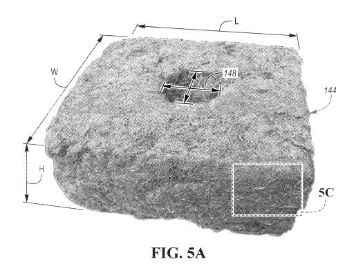
[0008] FIGURES 5A-5C are photographs of a non-limiting example of the
hydroponic
growing medium slab disclosed herein;
[0009] FIGURE 5D is a photograph of a non-limiting example of a
hydroponic growing
medium propagation portion disclosed herein;
[0010] FIGURE 6 shows a schematic depiction of an example microwave oven
capable of
binding the natural and man-made fibers disclosed herein;
10011] FIGURES 7A-9A are stereoscopic images of an example hydroponic
growing medium
at various magnifications;
2
CA 03078702 2020-04-07
WO 2019/074875 PCT/US2018/054927
[0012] FIGURES 7B-9B are stereoscopic images of an example prior art
substrate taken at the
same magnifications and of comparable thickness as respective growing medium
depicted in
FIGURES 7A-9A;
[0013] FIGURES 10-14 show volumetric water content at different pF values
for non-limiting
examples of the hydroponic growing media disclosed herein and a prior art
substrate.
DETAILED DESCRIPTION
[0014] Embodiments of the present disclosure are described herein. It is
to be understood,
however, that the disclosed embodiments are merely examples and other
embodiments may take
various and alternative forms. The figures are not necessarily to scale; some
features could be
exaggerated or minimized to show details of particular components. Therefore,
specific structural and
functional details disclosed herein are not to be interpreted as limiting, but
merely as a representative
basis for teaching one skilled in the art to variously employ the present
invention. As those of ordinary
skill in the art will understand, various features illustrated and described
with reference to any one of
the figures may be combined with features illustrated in one or more other
figures to produce
embodiments that are not explicitly illustrated or described. The combinations
of features illustrated
provide representative embodiments for typical applications. Various
combinations and modifications
of the features consistent with the teachings of this disclosure, however,
could be desired for particular
applications or implementations.
[0015] Except where expressly indicated, all numerical quantities in this
description indicating
dimensions or material properties are to be understood as modified by the word
"about" in describing
the broadest scope of the present disclosure.
[0016] The first definition of an acronym or other abbreviation applies
to all subsequent uses
herein of the same abbreviation and applies mutatis mutandis to normal
grammatical variations of the
initially defined abbreviation. Unless expressly stated to the contrary,
measurement of a property is
determined by the same technique as previously or later referenced for the
same property.
3
CA 03078702 2020-04-07
WO 2019/074875 PCT/US2018/054927
[0017] The description of a group or class of materials as suitable for a
given purpose in
connection with one or more embodiments of the present invention implies that
mixtures of any two
or more of the members of the group or class are suitable. Description of
constituents in chemical
terms refers to the constituents at the time of addition to any combination
specified in the description
and does not necessarily preclude chemical interactions among constituents of
the mixture once mixed.
The first definition of an acronym or other abbreviation applies to all
subsequent uses herein of the
same abbreviation and applies mutatis mutandis to normal grammatical
variations of the initially
defined abbreviation. Unless expressly stated to the contrary, measurement of
a property is determined
by the same technique as previously or later referenced for the same property.
[0018] Hydroponics, or soilless horticulture dates back to at least the
17th century. At that time,
the exploration of the solution hydroponics, or growing terrestrial plants
without any substrate or inert
medium contributed to understanding of essential elements and conditions for
plant growth. While
hydroponics gained its name due to plant growth in water, the term also
encompasses cultivation of
terrestrial plants in a substrate different from water as long as the
substrate is free from soil.
Nonlimiting example substrates include an expanded clay aggregate, growstones,
coir or coco peat,
rice husks, perlite, vermiculite, pumice, sheep wool, rock or mineral wool,
brick shards, polystyrene
packing peanuts, among other types.
[0019] In comparison with growing methods in soil, hydroponics presents
several advantages.
For example, the roots of the grown plants may have better access to the
beneficial amount of oxygen,
nutrients, and water than plants grown in soil. Yet, certain hydroponic
substrates which are being used
still have a variety of disadvantages. For example, polystyrene may release
styrene absorbable into
some plants and their fruit, which may present a health risk to the plant
consumer. Other substrates
such as brick shards may cause alteration of desirable pH. Yet alternative
substrates may negatively
affect hormones which regulate plant growth. Substrates such as peat may
harden and become too
dense with time.
[0020] One of the most commercially utilized hydroponic substrates has
been rockwool.
Rockwool, also known as mineral wool, is an inert substrate made from molten
rock such as basalt
4
CA 03078702 2020-04-07
WO 2019/074875 PCT/US2018/054927
and sand that is spun into bundles of single filament fibers. The fibers are
bonded into a medium
capable of capillary action. Rockwool growing media may be used in the form of
slabs or cubes
wrapped in a plastic packaging with several openings for drainage. The
hydroponic fluid is fed to the
top surface of the substrate and becomes available to the plants' root system
as it percolates via the
substrate due to gravitational forces. One of the disadvantages of the
rockwool material is mechanical
irritation of skin and lungs of a person handling the material, for example
during manufacture or use.
Another disadvantage is environmental burden as rockwool is very difficult to
dispose of. Practically,
after being used, the rockwool slabs may be buried, but rockwool does not
decompose, and thus
becomes an environmental burden. Additionally, rockwool has a high pH
requiring adjustment of the
hydroponic solution to arrive at a neutral pH in the zone of the root system.
An overall maintenance
of pH of the rockwool slabs is required as rockwool is subject to pH shifts.
Additionally still, rockwool,
due to its high water holding capacity (WHC), is susceptible to development
and retention of plant
diseases.
[0021] Thus, there is a need for a hydroponic growing medium overcoming
one or more of the
above-mentioned disadvantages.
[0022] In one or more embodiments, a hydroponic growing medium is
disclosed. The
hydroponic growing medium includes a mixture of a natural fiber portion and an
artificial or man-
made fiber portion. The term "growing medium" (GM) refers to a substrate,
specifically a soil-free
substrate or a combination of materials used to provide physical support,
water retention, aeration,
and/or nutrient supply for plant growth so that a plant can establish its root
system within the growing
medium and allow for root growth, as the roots grow in spaces between
individual particles of the
growing medium.
[0023] The natural fiber portion may include one or more wood components
including wood
chips, wood fiber, bark, leaves, needles, or their combination. The wood
components may be derived
from coniferous and/or deciduous trees and may be prepared by any convenient
manner, for example
as disclosed for wood fibers in U.S. 2,757,150. Any type of wood components
may be used, for
example wood components of the softwood varieties such as yellow poplar, cedar
such as Western red
CA 03078702 2020-04-07
WO 2019/074875 PCT/US2018/054927
cedar, fir such as Douglas fir, California redwood, and particularly pine such
as Ponderosa, Sugar,
White, and Yellow varieties of pine. Other useful wood components may come
from oak, walnut,
mahogany (Swietenia macrophylla, Swietenia mahagoni, Swietenia humilis),
hemlock, Douglas fir,
arborvitae, ash, aspen, basswood, butternut, hornbeam, beech, alder, elm,
birch, hemlock, hickory,
larch, locust, maple, cottonwood, chestnut, Sitka spruce, sycamore, sassafras,
shadbush, willow, fruit
trees like cheery, apple, and the like, and combinations thereof.
[0024] For example, wood components may refer to fibrous tree wood
components including
just fibrous tree wood or fibrous tree wood as well as fibrous tree bark,
needles, leaves, chips, or a
combination thereof. The term "bark" refers to a plurality of stem tissues
including one or more of
cork (phellum), cork cambium (phellogen), phelloderm, cortex, phloem, vascular
cambium, and
xylem.
[0025] Besides wood components named above, the natural fiber portion may
include peat,
coir, or both. Peat refers to partially decayed organic matter harvested from
peatlands, bogs, mires,
moors, or muskegs. Coir refers to fiber from the outer husk of the coconut.
[0026] The natural fiber portion may include about 5 to about 95 weight %
of tree bark mixed
with about 95 to about 5 weight % of wood components, coir, peat, or a
combination thereof, based
on the total weight of the natural fiber portion. The natural fiber portion
may include 100 weight %
fibrous pine wood components. The natural fiber portion may include about 10
weight % of tree bark,
peat, coir, or a combination thereof, and about 90 weight % of wood
components, based on the total
weight of the natural fiber portion. The natural fiber portion may include
about 20 to about 70 weight
% of tree bark and about 30 to about 80 weight % of wood components, based on
the total weight of
the natural fiber portion. Alternatively, the natural fiber portion may
include about 50 to about 60
weight % of tree bark and about 40 to about 50 weight % of wood components,
based on the total
weight of the natural fiber portion. The natural fiber portion may include
about 90 weight % of tree
bark and about 10 weight % of wood components, peat, coir, or a combination
thereof, based on the
total weight of the natural fiber portion.
6
CA 03078702 2020-04-07
WO 2019/074875 PCT/US2018/054927
[0027] The natural fiber portion may include 100% natural refined wood
fiber, for example in
the form of chips. Thus, the natural fiber portion may be free of any bark.
Such embodiment may have
an additional advantage of being free of components causing discoloration of
the hydroponic solution
once the hydroponic growing medium is being irrigated. While bark may cause
discoloration of the
solution, a bark-free natural refined wood fiber may keep the hydroponic
solution clear or of the
original color and thus enable an easier monitoring of nutrient levels. The
fiber used may be pine wood
fiber alone or in combination with other natural wood fiber.
[0028] The natural fiber portion may include about 0 to 20, 1 to 15, or 5
to 10 weight % of
peat, about 0 to 30, 5 to 25, or 10 to 20 weight % coir, based on the total
weight of the natural fiber
portion. The remainder of the natural fiber portion may be formed by the wood
components named
above. In one or more embodiments, the natural fiber portion may include a
substantial amount of peat
or coir such that up to 50, 60, 70, 80, 90, or 100 weight % of the natural
fiber portion is formed by
peat, coir, or a combination thereof.
[0029] The bark, coir, peat, and/or wood components may be preprocessed
in a variety of ways
such as cut so that the dimensions of the wood components, coir, peat, and/or
bark pieces are about
0.25 inches (0.64 cm) to about 6 inches long and wide, about 1 inch (2.54 cm)
to about 4 inches (10.2
cm) long and wide, or about 2 inches (5 cm) to about 3 inches (7.6 cm) long
and wide. The size of the
wood components, coir, peat, and/or bark pieces may be about 2 x 2 inches (5 x
5 cm).
[0030] The dimensions of the fibers in the natural fiber portion, such as
diameter, may be
modified. The modification may be done in a refiner.
[0031] Overall, the natural fiber portion represents a well graded
substrate which maintains
hydraulic conductivity, high porosity, and provides a high percentage of
available water to the plant,
partially due to the particle distribution within the natural fiber portion.
Example particle distribution
of the natural fiber portion is listed below in Table 1. Tables 2 and 3
provide additional properties data
of the natural fiber portion.
7
CA 03078702 2020-04-07
WO 2019/074875 PCT/US2018/054927
[0032] Table 1 ¨ Substrate particle distribution in the natural fiber
portion of the hydroponic
growing medium
Sieves [Mesh/pm] Particle Range [mm] Particle Distribution
[%]
1/4" / 6300 > 6.3 0.3
#4 / 4750 4.75 - 6.2 0.1
#8 / 2360 2.36 - 4.74 12.4
#16 / 1180 1.18 - 2.35 23.8
#25 / 710 0.71 - 1.17 24.2
#50 / 300 0.3 - 0.7 21.5
#100 / 150 0.15 - 0.29 10.3
Pan / <150 <0.15 7.3
[0033] Table 2 - Average length to width ratio of particles in sieves #16
and #50 of the natural
fiber portion
Sieve #16/1180 pm Sieve #50/300 pm
1.18-2.36 mm Particle Range 0.30-0.71 mm Particle Range
Average length to Width Ratio Range Average length to Width Ratio
Range
Lower Higher Lower Higher
14.899: 1 30.602: 1 39.615 : 1 55.507: 1
[0034] Table 3 ¨ Properties of two non-limiting examples of the natural
fiber portion
Components [%] Volume Volume of Dry bulk density Wet bulk
Moisture
of air space - density
content
range [1b/ft3] [kg/m3] [1b/ft3] [kg/m3] [%[
8
CA 03078702 2020-04-07
WO 2019/074875 PCT/US2018/054927
air [vol. %]
space
[vol. %]
80% wood, 20% 30.25 25 - 75 2.37 37.96 2.83 45.33
90.99
bark
100% pine wood 44.53 25 - 75 2.20 35.24 2.49 39.89
89.80
fiber
[0035] The data in Table 3 was collected by JR Peters Laboratory
Allentown, PA, USA, using
"Procedures for Determining Physical Properties of Horticultural Substrates
Using the NCSU
Porometer by Horticultural Substrates Laboratory," Department of Horticultural
Science, North
Carolina State University in Raleigh, North Carolina, which is incorporated in
its entirety by reference
herein.
[0036] The percent volume of air space in Table 3, and elsewhere within
this disclosure, refers
to air holding capacity measured as the percent volume of a substrate that is
filled with air after the
material is saturated and allowed to drain. It is the minimum amount of air
the material will have. The
analysis using the NCSU Porometer was performed on a 28.3 inch3 (463.8 cm3)
sample in a 3 x 3
inches (7.6 x 7.6 cm) aluminum cylinder.
[0037] The bulk density in Table 3, and elsewhere within this disclosure,
refers to the ratio of
the mass of dry solids to the bulk volume of the substrate. The bulk volume
includes the volume of
solids and pore space. The mass is determined after drying a packed core to
constant weight at 221 F
(105 C), and volume is that of the sample in cylinders.
[0038] The moisture content in Table 3, and elsewhere within this
disclosure, refers to the
percent moisture found in a sample on a wet mass basis. This is calculated by:
[(Wet weight - Dry
weight)/Wet weight] X 100. The moisture content denotes how much of a
particular sample is
comprised of water.
9
CA 03078702 2020-04-07
WO 2019/074875 PCT/US2018/054927
[0039] In comparison to the density data of Table 3, in at least one
embodiment, the initial
density of the wood components, coir, peat, and/or bark before the wood
components, coir, peat, and/or
bark are formed into a natural fiber portion by the process described below
may be about 15 lbs/ft3
(240.28 kg/m3) to about 35 lbs/ft3 (560.65 kg/m3) or 15, 16, 17, 18, 19, 20,
21, 22, 23, 24, 25, 26, 27,
28, 29, 30, 31, 32, 33, 34, or 35 lb/ft3.
[0040] The wood, coir, peat, and/or bark components may be combined with
additional
components. Examples of such additional components include, but are not
limited to, fertilizer(s),
macronutrient(s), micronutrient(s), mineral(s), binder(s), natural gum(s),
interlocking manmade
fiber(s), and the like, and combinations thereof. In general, these additional
components in total are
present in an amount of less than about 10 weight % of the total weight of the
natural fiber portion.
More preferably, the additional components in total are present in an amount
from about 1 to about 15
weight % of the total weight of the natural fiber portion. Soil is absent from
the natural fiber portion.
Fertilizers such as nitrogen fertilizers, phosphate fertilizers, potassium
fertilizers, compound
fertilizers, and the like may be used in a form of granules, powder, prills,
or the like. For example,
melamine/formaldehyde, urea/formaldehyde, urea/melamine/formaldehyde and like
condensates may
serve as a slow-release nitrogenous fertilizer. Fertilizers having lesser
nutritional value, but providing
other advantages such as improving aeration, water absorption, or being
environmental-friendly may
be used. The source of such fertilizers may be, for example, animal waste or
plant waste.
[0041] Nutrients are well-known and may include, for example,
macronutrient,
micronutrients, and minerals. Examples of macronutrients include calcium,
chloride, magnesium,
phosphorus, potassium, and sodium. Examples of micronutrients are also well-
known and include, for
example, boron, cobalt, chromium, copper, fluoride, iodine, iron, magnesium,
manganese,
molybdenum, selenium, zinc, vitamins, organic acids, and phytochemicals. Other
macro- and micro-
nutrients are well known in the art.
[0042] The binders may be natural or synthetic. For example, the
synthetic binders may
include a variety of polymers such as addition polymers produced by emulsion
polymerization and
used in the form of aqueous dispersions or as spray dried powders. Examples
include styrene-
CA 03078702 2020-04-07
WO 2019/074875 PCT/US2018/054927
butadiene polymers, styrene-acrylate polymers, polyvinylacetate polymers,
polyvinylacetate-ethylene
(EVA) polymers, polyvinylalcohol polymers, polyacrylate polymers, polyacrylic
acid polymers,
polyacrylamide polymers and their anionic- and cationic-modified copolymer
analogs, i.e.,
polyacrylamide-acrylic acid copolymers, and the like. Powdered polyethylene
and polypropylene may
also be used. When used, synthetic binders are preferably used in aqueous
form, for example as
solutions, emulsions, or dispersions. While binders are not ordinarily used in
growing media, they may
be useful in hydraulically applied growing media.
[0043] Thermoset binders may also be used, including a wide variety of
resole and novolac-
type resins which are phenol/formaldehyde condensates, melamine/formaldehyde
condensates,
urea/formaldehyde condensates, and the like. Most of these are supplied in the
form of aqueous
solutions, emulsions, or dispersions, and are generally commercially
available.
[0044] The natural binder may include a variety of starches such as corn
starch, modified
celluloses such as hydroxyalkyl celluloses and carboxyalkyl cellulose, or
naturally occurring gums
such as guar gum, gum tragacanth, and the like. Natural and synthetic waxes
may also be used.
[0045] With reference to Figure 1, a schematic flowchart illustrating the
formation of the
natural fiber portion is provided. As can be seen in Figure 1, in step a), an
initial composition 14 is
formed by combining tree bark 10, coir 11, wood components 12, and/or peat 13
together to form the
initial composition 14.
[0046] In step b), the initial composition 14 is heated to an elevated
temperature to kill
microorganisms in a pressurized vessel 16. Typically, the heating step may be
conducted at a
temperature in the range of about 250 F (121 C) or lower to about 500 F (260
C) or higher, about
300 F (149 C) to about 400 F (204 C), about 320 F (160 C) to 380 F (about 193
C). The heating
step may be conducted for a time sufficient to kill microbes. The heating step
may be conducted for
about 1 to about 5 minutes or longer under a steam pressure of about 35
lbs/in2 (2.4 kg/cm2) to about
120 lbs/in2 (8.4 kg/cm2) or about 50 lbs/in2 (3.5 kg/cm2) to about 100 lbs/in2
(7.0 kg/cm2). For example,
the heating step may be conducted at a temperature of about 300 F (149 C) for
about 3 minutes at
11
CA 03078702 2020-04-07
WO 2019/074875 PCT/US2018/054927
about 80 lbs/in2 (5.6 kg/cm2). For example, the heating step may be conducted
at a temperature of
about 300 F (149 C) for about 3 minutes. The heating step results in a
preferably substantially sterile
natural fiber portion such that the natural fiber portion is free from
bacteria or other living organisms.
The steam flow rate during the heating step may be from about 4000 lbs/hour
(1814 kg/hour) to about
15,000 lb/hour (6803 kg/hour).
[0047] An example of a pressurized vessel and related process for step b)
is disclosed in U.S.
Pat. No. 2,757,150, which has been incorporated by reference, in which wood
chips are fed to a
pressurized steam vessel which softens the chips.
[0048] In step c), the initial composition 14 is processed through a
refiner 18 to form the
natural fiber portion 20. The refiner 18 may use a plurality of disks to
obtain the natural fiber portion
20. The refiner 18 may use two or more disks, one of which is rotating, to
separate wood, bark, peat,
coir fibers from each other as set forth in U.S. Pat. No. 2,757,150, the
entire disclosure of which is
hereby incorporated by reference. The refiner 18 is usually operated at a
lower temperature than the
temperature used in step b). The refiner 18 may be operated at a temperature
in the range of about
70 F (21 C) to about 400 F (204 C), about 150 F (66 C) to about 350 F (176 C),
about 200 F (93 C)
to about 300 F (148 C). The refiner 18 may be operated under steam. The
refiner 18 may be operated
at atmospheric pressure or elevated pressures such as pressures of about 50
lb/in2 (3.5 kg/cm2) or lower
to about 100 lb/in2 (7.0 kg/cm2). Some of the additional components 21 may be
added during step c)
such as a dye or a surfactant.
[0049] In step d), the natural fiber portion 20 is dried at temperatures
of about 400 F (204 C)
to about 600 F (316 C) for the time sufficient to reduce the moisture content
of the natural fiber
portion 20 to a value less than about 45 weight %, less than about 25 weight
%, or less than about 15
weight %, based on the total weight of the natural fiber portion 20. The
drying step may be about 1 to
seconds long, about 2 to 8 seconds long, about 3 to 5 seconds long. The drying
step may be longer
than 10 seconds. Exemplary equipment for drying of the natural fiber portion
20 in step d) may be a
flash tube dryer capable of drying large volumes of the natural fiber portion
20 in a relatively short
length of time due to the homogeneous suspension of the particles inside the
flash tube dryer. While
12
CA 03078702 2020-04-07
WO 2019/074875 PCT/US2018/054927
suspended in the heated gas stream, maximum surface exposure is achieved,
giving the natural fiber
portion 20 uniform moisture. The moisture content of the natural fiber portion
20 may be from about
to about 50 weight %, about 20 to about 40 weight %, about 25 to about 35
weight % of the total
weight of the natural fiber portion 20.
[0050] The combination of steps b), c), and d) may result in a stable
growing medium which
may be sterile.
[0051] In an optional step e), the natural fiber portion 20 is further
refined, and the additional
components 21 set forth above may be added.
[0052] The natural fiber portion is subsequently combined with the man-
made fiber portion.
The natural fiber portion may be provided in the compressed and/or expanded
form. The natural fiber
portion to be mixed with the man-made fiber portion may have a density of
about 1.1 to 1.8 lbs/ft3,
1.2 to 1.6 lb s/ft3, or 1.3 to 1.5 lb s/ft3.
[0053] Likewise, the man-made fiber portion may be provided in the
compressed and/or
expanded form. If compressed man-man fiber is provided, decompression and
expansion of the fiber
is desirable such that the man-made fiber reaches a density of about 0.45 to
0.75 lb/ft3, 0.5 to 0.65
lb/ft3, or 0.55 to 0.6 lb/ft3.
[0054] The man-made fiber may be a bicomponent fiber such that it
contains at least two
different types of material and/or fiber. The man-made fiber portion may
include at least one kind of
bicomponent fiber. The man-made fiber portion may include a plurality of
bicomponent fibers,
forming a mixture. Each fibrous piece may contain an outer shell made from the
first fiber and an inner
portion, a core, made from the second fiber. Having a bicomponent fiber may
allow melting of a
portion of the bicomponent fiber while allowing some of the fiber to remain in
a non-melted state.
Melting of the outer shell may enable adherence of the man-made fiber to the
natural fiber portion
while preserving structure of the man-made fiber as the inner core does not
succumb to melting.
Alternatively, a single component man-made fiber may be used in combination
with an adhesive. The
adhesive may be an adhesive named above.
13
CA 03078702 2020-04-07
WO 2019/074875 PCT/US2018/054927
[0055] The man-made fiber or bicomponent fiber may include any artificial
fiber. The man-
made fiber may include as a core, the outer shell, and/or the single component
the following:
thermoplastic fibers, polyolefins such as polyethylene, polypropylene,
polyethylene terephthalate,
polytetrafluoroethylene, polyphenylene sulfide, polyesters, polyethers such as
polyethereketone,
polyamide such as nylon 6, nylon 6,6, regenerated cellulose such as rayon,
aramid, fiberglass,
polybenzimidazole, carbon/graphite, a combination thereof, or the like. For
example, bicomponent
fiber may include a polyester core and a polypropylene outer shell or sheet or
polyethylene or linear
low density polyethylene outer shell. In another example, the bicomponent
fiber may include a
polypropylene core and a polyethylene outer shell. In a yet another example, a
polyamide core and a
polyolefin outer shell may be included. A non-limiting example of the man-made
fiber being
structured as a bicomponent fiber is shown in Table 4 below.
[0056] The man-made fiber may be hydrophobic or hydrophilic. The man-made
fiber may be
biodegradable such that the material used lasts for the length of the growing
season, but is relatively
easily biodegradable afterwards. Alternatively, if non-biodegradable man-made
fiber is used, the man-
made fiber may be separated from the remaining components of the hydroponic
growing medium after
use and recycled.
[0057] Table 4 ¨ Properties of an example bicomponent man-made fiber
including a low melt
fiber with a melting point of 110 0 as an outer shell and polyester fiber with
a melting temperature of
258 0 forming the core of the man-made fiber.
Property of the sheath material Range of Control [unit]
Denier 14.00 1.00 [g/9000M]
Strength 3.30 0.4 [g/DE]
Elongation 80.00 15.00 [Vo]
Crimp Number 7.00 2.00 [EA/Inch]
Oil Pick-up 0.12 0.05 [Vo]
Heat Shrinkage 4.50 2.00 [Vo]
Melting Point 110 [ 0]
14
CA 03078702 2020-04-07
WO 2019/074875 PCT/US2018/054927
Fiber Length 51.0 1.00 [mm]
[0058] The man-made fiber may have denier of about 0.9 to about 15, 2 to
13, or 4 to 10 or
0.9, 1, 1.2, 1.5, 2, 2.5, 3, 4, 5, 6, 7, 8, 9, 10, 11, 12, 13, 14, or 15.
Bicomponent fibers with higher
denier values are also contemplated, for example denier of about 16 to 30, 18
to 25, or 20 to 24. It has
been unexpectedly discovered that including bicomponent fibers of finer denier
such as the values
named above, a lower weight percentage of the bicomponent fiber may be
included while achieving
adequate or even more efficient bonding of the natural and man-made fiber than
if man-made fibers
of higher denier are used in higher weight percentage.
[0059] The length of the bicomponent fiber may vary such that a mixture
of lengths may be
included in the man-man fiber portion. Alternatively, fibers having
significantly similar length may
be included in the man-made fiber portion. The length of the man-made fiber
may be about 0.5 to 5
inches, 1 to 4 inches, or 1.5 to 3 inches or 0.5, 1, 1.5, 2, 2.5, 3, 3.5, 4,
4.5, or 5 inches.
[0060] The core material of the man-made fiber may have melting
temperature of about 130 C
to 260 C, 150 C to 220 C, or 180 C to 200 C. While the core may be located
central with respect to
the geometry of the fiber having a circular profile, it is also possible to
use fiber having the first fiber
and the second fiber arranged side by side, such that the first fiber and the
second fiber form a portion
of the outer shell. The ratio of the first fiber to the second fiber may be
about 80:20 to 20:80, 70:30 to
30:70, 60:40 to 40:60, or about 50:50.
[0061] The man-made fiber is included to lower bulk density of the
overall fiber mixture 28.
In addition, the man-man fiber provides additional structure to the natural
fiber portion such that the
hydroponic growing medium resists compression and pot shrinkage. As a result,
the hydroponic
growing medium maintains its structure throughout an extended grow period of
10-12 months or
beyond, the hydroponic growing medium remains to be highly oxygenated by not
collapsing on itself
due to compromised structure as the organic components break down over time.
The man-made fiber
portion thus ensures that, unlike other hydroponic growing media containing an
organic component
CA 03078702 2020-04-07
WO 2019/074875 PCT/US2018/054927
which suffer from the organic portion degradation over time, the disclosed
hydroponic growing
medium remains stable and oxygenated throughout the entire grow period. The
inclusion of the man-
made fiber prevents reduction in porosity caused by the presence of the
organic matter within the
hydroponic growing medium.
[0062] With reference to Figure 2, in step f), the expanded natural fiber
portion 22 and the
expanded man-made fiber portion 24 are combined. Combination of the expanded
natural fiber portion
22 and the expanded man-made fiber portion 24 may be conducted on a conveyor
belt leading to a pin
mixer 26 or directly in the pin mixer 26 to form a fiber mixture 28.
[0063] The fiber mixture 28 may include at least about 2 to 30 wt.%, 5 to
20 wt.%, or 10 to 15
wt.% of the man-made fiber portion, based on the total weight of the fiber
mixture 28. The fiber
mixture 28 may include about 0.5, 1, 1.5, 2, 2.5, 3, 3.5, 4, 4.5, 5, 6, 7, 8,
9, 10, 11, 12, 13, 14, 15, 16,
17, 18, 19, 20, 21, 22, 23, 24, 25, 26, 27, 28, 29, or 30 wt. % of the man-
made fiber portion, based on
the total weight of the fiber mixture 28. The fiber mixture 28 may thus
include at least about 70 to 98
wt.%, 80 to 95 wt.%, or 85 to 90 wt.% of the natural fiber portion, based on
the total weight of the
fiber mixture 28. The fiber mixture 28 may include about 99.5, 99, 98.5, 98,
97.5, 97, 96.5, 96, 95.5,
95, 94, 93, 92, 91, 90, 89, 88, 87, 86, 85, 84, 83, 82, 81, 80, 79, 78,77, 76,
75, 74, 73, 72, 71, or 70 wt.
% of the natural fiber portion, based on the total weight of the fiber mixture
28. As was stated above,
the finer the denier of the man-made fiber, the lower weight percentage of the
man-made fiber may be
incorporated. For example, about 2 weight % bicomponent fiber having denier of
about 4 may be
combined with about 98 weight % of the natural fiber portion.
[0064] To further assist with bonding of the man-made fiber and the
natural fiber, one or more
types of chemical binders may be included. Chemical binders may include those
named above and
may include natural binders, synthetic binders, or a combination of binders.
[0065] During step f), the bulk density of the fiber mixture 28 in the
pin mixer 26 reaches
values of about 0.6 to 1.5 lb/ft3, 0.8 to 1.2 lb/ft3, or 1 to 1.1 lb/ft3 or
about 0.6, 0.7, 0.8, 0.9, 1, 1.1, 1.2,
1.3, 1.4, 1.5 lb/ft3. As is apparent from these values, the inclusion of the
man-made fiber portion 24
16
CA 03078702 2020-04-07
WO 2019/074875 PCT/US2018/054927
significantly reduces the bulk density of the overall fiber mixture 28. The
fiber mixture 28 may be
used to grow terrestrial plants without further processing.
[0066] Yet, it is desirable to form the fiber mixture 28 into a
hydroponic growing medium in
the form of a slab, block, cube, or another shape suitable for hydroponic
growing and convenient for
transportation to a distributor or consumer. The process incorporates heat
and/or pressure to bind the
natural fiber portion 22 and the man-made fiber portion 24 into a block 40 of
similar or different
dimensions than the prior art slabs such as rockwool slabs.
[0067] Thus, in step g), a metered volume of the fiber mixture 28 is
transported to a separator
condenser 30. The transport may be arranged via air lift of the fiber mixture
28 to an air/material
separator condenser 30. The fiber mixture 28 continues onto a conveyor belt,
where the fiber mixture
28 accumulates until a metered volume accumulates within a predefined space.
For example, the
accumulated volume may reach a depth or thickness di of about 5 to 20, 10 to
18, or 12 to 15 inches.
The depth may vary depending on the dimensions of the desired product.
[0068] In step h), the metered volume is passed through a series of
rollers 32 which compress
the loose metered volume to a predetermined compressed thickness d2 being 30
to 90%, 40 to 80%, or
50 to 70% lower than di. d2 is about 1 to 6, 2 to 5, or 3 to 4 inches thick,
defining a compressed matrix
34 having a shape resembling a slab. The compressed matrix 34 has a thickness
which is about 100 to
500%, 200 to 400%, or 300 to 350% of the original thickness of the loose
metered volume. For
example, the loose metered volume may have thickness of about 12 inches at the
end of step j). After
passing through the rollers 32, the compressed matrix 34 may have thickness of
about 3 inches (400%)
or 4 inches (300%).
[0069] Subsequently, in step i), the compressed matrix 34 advances to an
oven 36 to bind the
natural fiber portion 22 and the man-made fiber portion 24 to form intimate
bonds between the two
types of fibers. The oven temperature is set to a temperature which has a
value of at least the melting
temperature of the outer shell of the man-made fiber or the low-melt component
of the man-made fiber
with the lowest melting point such as the outer shell of the man-made fiber.
For example, when the
17
CA 03078702 2020-04-07
WO 2019/074875 PCT/US2018/054927
man-made fiber is a bicomponent fiber including a low-melt first fiber (first
material), the oven should
be set at least at the temperature which equals the melting point of the low-
melt first fiber. The
temperature will cause melting of the first fiber while the second fiber
(second material, such as the
material of the core) will remain in its non-melted state. The natural and man-
made fibers are adhered
together while the man-made fiber portion 24 retains its structure and
provides support for the natural
fiber portion 22.
[0070] The oven may be enclosed or open which will determine the duration
of the step i). For
example, if the matrix material 34 is within a four-sided mold in the oven,
step i) may last several
minutes such as about 5 to 20 minutes, 7 to 15 minutes, or 9 to 10 minutes. If
the matrix 34 is not
placed within a mold such that the hot air may pass through the matrix 34, the
step i) may take less
time such as 2 to 5 minutes.
[0071] Binding of the natural fiber portion 22 and the man-made fiber
portion 24 may be
performed using dielectric heating, electronic heating, RF (radio frequency)
heating, or high-
frequency heating. The dielectric heating used may utilize microwaves.
Microwaves are a form
of electromagnetic radiation with wavelengths ranging from one meter to one
millimeter;
with frequencies between 300 MHz MO cm) and 300 GHz (0.1 em). For example, one
or more
microwave ovens may be used in step i) and/or other steps of the process
described herein. The one or
more microwave oven(s) may use a frequency from about 2.45 Gilz (wavelength of
12.2 cm) to about
915_MHz (wavelength of 32.8 cm) or 433.92 MHz. Other frequencies and
wavelengths are
contemplated. The microwave oven(s) may be a microwave tunnel oven featuring
an elongated body.
The microwave oven(s) may be a microwave dryer. The microwave oven may include
one or more
portions.
[0072] A nonlimiting schematic example of a microwave oven is depicted in
Figure 6. The
microwave oven 50 may include a generator 52, a waveguide 54, and an
applicator 56. The generator
52 generates energy at the frequencies mentioned above such as 915 MHz or 2450
MHz. The generator
52 may include a magnetron, electromagnet, a power supply unit, circulator, a
water load, which may
18
CA 03078702 2020-04-07
WO 2019/074875 PCT/US2018/054927
be housed in an enclosure. The enclosure may be mounted to a hard surface such
as a floor. A flow of
water may be used for cooling of the generator 52.
[0073] The waveguide 54 conveys microwave energy from the generator 52 to
the applicator
56. The waveguide 54 may have a plurality of interconnected portions. The
waveguide 54 allows the
generator 52 to be located in a separate area away from the applicator 56, at
a distance of up to about
30 m (100 feet). The waveguide 54 may include one or more manual tubing stubs
allowing an operator
to optimize microwave energy absorption of the fiber, dependent on the fibers'
dielectric properties
and temperature.
[0074] The microwave oven may be controlled manually or automatically. If
operated
automatically, the microwave oven 52 may include a control system (not
depicted) capable of
adjusting one or more variables such as generator power output, reflected
power, fiber exit
temperature, a combination thereof, or the like. The control system may
include one or more
programmable logic controllers (PLC)s, screen control panels, devices for data
acquisition, power
monitoring, temperature monitoring, moisture monitoring, and the like. The
control system may
further include one or more alarm features capable of identifying, recording,
and/or assisting in
resolution of one or more process control issues.
[0075] The applicator 56 contains and distributes the microwave energy
around the material
passing through the applicator 56. The fiber material may be moving via the
applicator 56 on a
conveyor belt 58, which may assist in uniform movement of the material via the
applicator 56. The
conveyor belt 58 may have a preset or variable speed control. The applicator
56 may be a multi-mode
device. The applicator 56 may have a variety of shapes. For example, the
applicator 56 may be
elongated. The applicator 56 may be shaped like a tunnel, a hollow conduit, or
recess. The applicator
56 may or may not include one or more exhaust fans to accommodate a
predetermined desired level
of material drying or dehydration.
[0076] Thus, the natural fiber portion 22 and the man-made fiber portion
24 may be heated
and/or bound in the applicator 56 while passing through the applicator 56, for
example on a conveyor
19
CA 03078702 2020-04-07
WO 2019/074875 PCT/US2018/054927
belt 58. The fibers may thus efficiently absorb the microwave energy to
achieve the desired final
temperature and moisture content discussed in this application as well as
become stable, and/or sterile.
[0077] The above-described process may utilize about 1 -10 pcf, 2-8 pcf,
or 4-6 pcf of a blend
of the natural fiber portion 22 and the man-made fiber portion 24. The process
may also use about 5 -
125 kW, 10- 100 kW, or 15 to 75 kW of power. The process may utilize about 300
MHz to 6000 MHz
operating frequencies besides those named above such as 915 MHz. Depending on
the dimensions of
the microwave oven, amount, density, moisture content and other properties of
the fiber passing
through, the blend of fibers 22 and 24 may pass through the microwave oven in
about 1 ¨ 10 minutes,
2 ¨ 8 minutes, or 3 ¨ 6 minutes.
[0078] An additional heat source may be used in conjunction with the
microwave oven. The
additional heat source may also utilize dielectric heating. The heating in
step i) may be rapid and/or
uniform. Dielectric heating may be used in any other step of the process
described herein requiring
elevated temperatures.
[0079] Step j) follows immediately after the first fiber melts such that
a series of rollers 38
applies pressure to the compressed matrix 34 which is now at least partially
melted due to the melt of
the outer shell material. The rollers 38 may have the same or different
dimensions. The rollers 38 may
be smooth or include less then smooth texture. At least some of the rollers 38
may be heated during
the step j). The pressure from the series of rollers 38 allows the matrix 34
to further bond the man-
made fiber to the natural fiber within the compressed matrix 34, and to hold
its structure. Compression
applied by the rollers 38 may be about 2.5 to 3.5 times the original bulk
density of the fiber mixture
28 from step f).
[0080] The compressed matrix 34 may be cooled before the pressure from
the rollers 38 is
released. The cooling may be provided by exposure to ambient air having
approximately room
temperature of about 18 0 (64 0 ) to about 21 0 (70 0 ) or by passing cool air
over the matrix 34 in the
rollers 38.
CA 03078702 2020-04-07
WO 2019/074875 PCT/US2018/054927
[0081] After cooling, in step k), the compressed matrix 34 of the
hydroponic growing medium
39 retains its structure, forming a 3-dimensional hydroponic growing medium
slab, cultivation slab,
structure, or substrate 40, which may be used for horticultural applications
such as growing fruit,
herbs, and/or vegetables in climate controlled environments The term slab
generally relates to the
shape of the hydroponic growing medium substrate. The slab may have a
generally rectangular shape.
Yet, the slab may have any other shape such as square, polygon, circle, oval,
or the like. The slab is
three-dimensional.
100821 In step 1), the slab 40 is placed in a packaging, covering,
sheath, or bag 42 to reduce
drying of the growing medium when used in a greenhouse, forming a slab 44. A
plurality of slabs 44
may be accumulated and pelletized for shipment to consumers. Yet, the
hydroponic growing substrate
retains its structure and/or configuration even when no bag is included, as
can be seen in Figures 5A-
5C. The hydroponic growing medium may be further compressed, for example by a
grower inserting
a propagation cube, a plant, or seeds in the substrate, and the substrate will
retain its shape and return
to its pre-compression state after the pressure is released. The hydroponic
growing medium disclosed
herein may thus be a self-supporting structure, capable of holding its shape
and/or structure without
an additional aid. The bag 42 may be loose and opened on at least one side.
Alternatively, the bag 42
may be a sealed bag, enclosing the slab 44 within the bag 42. In at least one
embodiment, the slab 44
may be enclosed by the bag 42 on less than all sides. For example, the slab 44
may be attached to a
plastic sheath only on its bottom side, one or more of the sides, or have the
plastic sheath placed only
on top. Alternatively still, the slab 44 may be loosely placed in a bag for
transportation but used for
hydroponic purposes without the bag coverage.
[0083] An example of the slab 44 can be seen in Figure 3. The slab may
have varying
dimensions. Each slab may have consistent or varying dimensions, depending on
the needs of a
specific application. Example dimensions may include a width w of about 6
(15.24 cm) to 8 inches
(20.32 cm) to 12 inches (30.48 cm), length 1 of about 36 (91.44 cm) to 40
inches (101.6 cm) to 78.7
inches (200 cm), and a height h of about 3 (7.62 cm) to 4 inches (10.16 cm).
Dimensions such as height
may be uniform throughout the length of the bag 44. Alternatively, certain
portions of the bag 4 may
21
CA 03078702 2020-04-07
WO 2019/074875 PCT/US2018/054927
have a smaller height than the remaining portions. For example, one or more
portions around the
corners may have a smaller height than the remaining portions.
[0084] Another example may be one or more portions which are designed to
house the plant
itself such that one or more areas for this purpose are imprinted in the slab,
the area having a smaller
height than the surrounding areas by up to about 50%. Such an area or portion
may form a cavity, a
hollowed-out space, an unfilled space or a hole within the mass of the
hydroponic growing medium.
The cavity may be defined as a cut-out or a recess in the body of the
hydroponic growing substrate
structure. The cavity may have a length which equal a height of the slab.
Alternatively, the cavity or
recess may be shallower than a height of the slab. The cavity may reach a
certain depth di of about 5,
10, 15, 20, 25, 30, 45, 50, 55 % of the slab's height. An example cavity 148
may be seen in Figures
5A-5C. Example non-limiting dimensions of the cavity or recess may include a
diameter of about 1 ¨
20 cm, 2 ¨ 15 cm, or 5 ¨ 10 cm and a depth of about 2 ¨20 cm, 5 ¨ 15 cm, or 7 -
10 cm. Furthermore,
the areas which are meant to accommodate majority of the root volume may have
an increased height
in comparison to the average height of the slab by about up to 25%.
[0085] The cavity may have varying dimensions and/or shapes and may be
large enough to
accommodate a propagation or grow portion. The propagation portion is designed
to enable seedlings
to sprout within the propagation portion. The entire propagation portion may
be later incorporated into
the slab, for example inserted into the cavity, when the plant is ready to
root in a larger root zone.
[0086] A slab may include one or more cavities. The cavities may have the
same or different
dimensions and/or shape. A configuration of the cavities may differ or be the
same in a plurality of
slabs and may be regular, irregular, symmetrical, asymmetrical.
[0087] The propagation portion may be a cube or may have a different
shape such as having a
circular, rectangular, oval, polygonal, regular, irregular, symmetrical, or
asymmetrical cross-section.
The propagation portion may have various dimensions and shapes, for example 1
x 1 x 1 inch, 2 x 2 x
2 inches, 4 x 4 x 4 inches, 6 x 6 x 6 inches. The propagation portion may
include a cavity in a top side
of the propagation portion to accommodate one or more seeds. The cavity may be
located in the center
22
CA 03078702 2020-04-07
WO 2019/074875 PCT/US2018/054927
of the top side of the propagation portion. A non-limiting example of a
propagation portion is a
propagation cube 200 depicted in Figure 5D.
[0088] The propagation portion may be made according to the process
described above and
include materials described herein. Yet, the preparation portion may differ in
at least one biological,
physical, chemical, and/or bio-physical property described herein from the
hydroponic growing
medium forming a slab. Such property may be dry bulk density, volumetric water
content, percent of
air space, total porosity, or the like.
[0089] For example, the propagation portion may have dry bulk density
which may be 10, 15,
20, 25, 30, 35, 40, 45, 50, 55, or 60 % higher than dry bulk density of the
slab. The greater density of
the propagation portion may have the advantage of accommodating specific needs
of a seed or a
seedling such as higher demand for water. The propagation portion may have an
increased water
retention as a result of the increased dry bulk density.
[0090] Alternatively, the formed slabs may be cut into smaller
configurations to form the
propagation portions. Cutting may be provided by laser or other cutting means.
Depending on the final
dimensions of the slab 44, a number of apertures 46 may be formed in the bag
42. Alternatively, the
bag 44 may contain weakened areas 46 such as perforated portions, where
apertures 46 may be created
by a consumer. The apertures 46 may serve for draining of excess hydroponic
liquid to be supplied to
a growing plant. Alternatively, at least some of the apertures 46 may serve
for placement of the plant(s)
within the hydroponic growing medium arranged within the bag 44. Such
apertures 46 may be placed
above the portions of the slab with lower thickness, each such portion forming
a recess, depression,
dent, indentation, or cavity, which is ready to accommodate the plant and/or a
propagation cube.
[0091] The bag 42 may be made from plastic such as thermoplastics named
above.
Alternatively, the bag 42 may be made from natural materials capable of
lasting in an undisintegrated
state for the length of the growing season or beyond such as 10 to 12 months
or longer. Such material
may include woven fiber of the types named above, possibly in combination with
a thin biodegradable
plastic foil liner. Using such material would even further increase
environmental friendliness of the
23
CA 03078702 2020-04-07
WO 2019/074875 PCT/US2018/054927
disclosed hydroponic growing medium due to an ecological disposal of the
disclosed hydroponics
growing medium slab in its entirety.
[0092] An example of the hydroponic growing medium 39 slab 144 is
depicted in Figures 5A-
5C. A perspective side view of the slab 144 is captured in Figure 5A. The top
view of the slab 144 is
shown in Figure 5C. The slab 144 includes a recess 148 to accommodate a
propagation portion such
as propagation cube or a plant. The recess 148 is central to the rectangular-
shaped slab 144. The non-
limiting example dimensions of the slab 144 are 10 cm x 22 cm x 18 cm. The
depth dp of the recess
is about 5 cm. Figure 5B shows a detailed view of the slab 144 and its fibrous
structure.
[0093] The bulk density of the hydroponic growing medium slab is lower
than density of other
hydroponic media such as the rockwool slab or growing media used for other
than hydroponic
purposes. For example, bulk density of the disclosed hydroponic medium may be
lower than 5.5 lb/ft3,
lower than 5.4 lb/ft3, lower than 5.3 lb/ft3, lower than 5.2 lb/ft3, lower
than 5.1 lb/ft3, lower than 5.0
lb/ft3, lower than 4.8 lb/ft3, lower than 4.6 lb/ft3, lower than 4.5 lb/ft3,
lower than 4.4 lb/ft3, lower than
4.2 lb/ft3, lower than 4.0 lb/ft3, lower than 3.8 lb/ft3, lower than 3.5
lb/ft3, lower than 3.2 lb/ft3, lower
than 3.0 lb/ft3, lower than 2.8 lb/ft3, lower than 2.5 lb/ft3, lower than 2.0
lb/ft3. The bulk density of the
disclosed hydroponic medium may be about 1.5 to 15, 1.8 to 10, 2 to 5, or 2.2
to 3.0 lb/ft3. The bulk
density of the disclosed hydroponic medium may be about 1.5, 1.8, 1.9, 2.0,
2.1, 2.2, 2.3, 2.4, 2.5, 2.6,
2.7, 2.8, 2.9, 3.0, 3.1, 3.2, 3.3, 3.4, 3.5, 3.6, 3.7, 3.8, 3.9, 4.0, 4.1,
4.2, 4.5, 4.8, 5.0, 5.2, 5.5, 5.7, 5.9,
6.0, 6.2, 6.5, 6.8, 7.0, 7.2, 7.5, 7.7, 8.0, 8.2, 8.5, 8.7, 9.0, 9.2, 9.5,
9.7, 10.0, 10.2, 10.5, 10.7, 11.0, 11.2,
11.5, 11.7, 12.0 12.5, 13.0, 13.5, 14.0, 14.5, 15.0 lb/ft3. The dry bulk
density of the disclosed
hydroponic medium may be 15.0 lb/ft3 or lower, 14.0 lb/ft3 or lower, 13.0
lb/ft3 or lower, 12.0 lb/ft3
or lower, 11.0 lb/ft3 or lower, 10.0 lb/ft3 or lower, 9.0 lb/ft3 or lower, 8.0
lb/ft3 or lower, 7.0 lb/ft3 or
lower, 6.0 lb/ft3 or lower, 5.0 lb/ft3 or lower, 4.0 lb/ft3 or lower, 3.8
lb/ft3 or lower, 3.6 lb/ft3 or lower,
3.4 lb/ft3 or lower, 3.2 lb/ft3 or lower, 3.0 lb/ft3 or lower, 2.8 lb/ft3 or
lower, 2.6 lb/ft3 or lower, 2.4
lb/ft3 or lower, 2.2 lb/ft3 or lower, 2.0 lb/ft3 or lower.
[0094] Total porosity of the hydroponic growing medium may be about 85 to
99 volume %,
90 to 97 volume %, or 92 to 95 volume %. Total porosity of the hydroponic
growing medium may be
24
CA 03078702 2020-04-07
WO 2019/074875
PCT/US2018/054927
greater than about 85, 85.5, 86, 86.5, 87, 87.5, 88, 88.5, 89, 89.5, 90, 90.5,
91, 91.5, 92, 92.5, 93, 93.5,
94, 94.5, 95, 95.5, 96, 96.5, 97, 97.5, 98, 98.5, or 99 volume %.
[0095] Comparison of various properties of an example hydroponic growing
medium slab, a
rockwool slab, and a non-hydroponic growing medium are listed in Table 5
below. The WHC in Table
has been determined by modified ASTM D7367 ¨ Standard Test Method for
Determining WHC of
Fiber Mulches for Hydraulic Planting. The density was measured as weight of
the slab divided by
volume of the slab.
[0096] Table 5 ¨ Comparison of physical properties of various hydroponic
and non-
hydroponic substrates.
Type of substrate Hydroponic use WHC [wt. Density [1b/fe] Loss of
Ignition [%]
%]
Hydroponic Yes 600 50 2.8 0.6 99.7
0.3
growing medium
slab
Rockwool slab Yes 1834 100 5.7 0.3 10
0.5
Non-hydroponic No 911 50 7 0.3 99.7
0.3
growing medium
mat
[0097] As Table 5 illustrates, the disclosed hydroponic growing medium
slab has a
significantly reduced density compared to the rockwool slab and to the non-
hydroponic growing
medium. The reduced density achieved by the process described above
incorporating sets of rollers
and thermal treatment ensures sufficiently strong structure which enables
proper support of the plants
throughout the extended growing season. The lower density also supports a root
structure having a
robust root system including numerous very thin roots. The intricate root
system has thinner roots
divided into thin and fine roots resembling hair. The fine fibrous system is
thus enabled to absorb more
CA 03078702 2020-04-07
WO 2019/074875 PCT/US2018/054927
nutrients via its many endings. In comparison, substrates with density which
exceeds the values
provided for the hydroponic growing medium slab result in a growth of thicker
roots which are less
efficient in absorption of nutrients from the hydroponic liquid.
[0098] The WHC of the hydroponic growing medium slab presents another
advantage. The
hydroponic growing medium slab has ability to provide sufficient pore space,
oxygenation, and ability
to percolate the hydroponic liquid via the root system and the slab. Higher
values of WHC, such as
WHC associated with the rockwool slab, translate into prolonged retention of
water within the slab,
reduced oxygenation of the slab and root system, and eventually an increased
chance for development
of undesirable plant diseases and parasites or fungi such as Pythium.
[0099] The container capacity or total WHC of the hydroponic growing
medium may be about
40- 80, 50- 75, or 60 - 65 wt. %. The container capacity may be lower than
about 80, 75, 70, 65, 60,
55, or 50 wt. %. The container capacity may be from about 40, 45, 50, 55, 60,
65, 70, 75, 80, or 85 to
85, 80, 75, 70, 65, 60, 55, 50, 45 to 40 wt. %.
101001 The percent of air space of the hydroponic growing medium may be
about 30 to 60, 40
to 55, or 50 to 53. The percent of air space may be 30, 31, 32, 33, 34, 35,
36, 37, 38, 39, 40, 41, 42,
43, 44, 45, 46, 47, 48, 49, 50, 51, 52, 53, 54, 55, 56, 57, 58, or 60.
[0101] The volumetric water content of the hydroponic growing medium at
pF 0.5 may be
about 50 to 70 %, 55 to 65 %, or 60 to 63 %. The volumetric water content of
the hydroponic growing
medium at pF 1 may be about 50, 51, 52, 53, 54, 55, 56, 57, 58, 60, 61, 62,
63, 64, 65, 66, 67, 68, 69,
or 70 %. The volumetric water content of the hydroponic growing medium at pF
0.5 may be lower
than 95, 92, 90, 88, 85, 82, 80, 78, 75, 72, 70, 67, 65, 62, 60, 58, 55, 50,
or 45 %.
[0102] The volumetric water content of the hydroponic growing medium at
pF 1 may be about
25 to 70 %, 30 to 60 %, or 40 to 50 %. The volumetric water content of the
hydroponic growing
medium at pF 1 may be about 25, 26, 27, 28, 29, 30, 31, 32, 33, 34, 35, 36,
37, 38, 39, 40, 41, 42, 43,
44, 45, 46, 47, 48, 49, 50, 51, 52, 53, 54, 55, 56, 57, 58, 60, 61, 62, 63,
64, 65, 66, 67, 68, 69, or 70 %.
26
CA 03078702 2020-04-07
WO 2019/074875 PCT/US2018/054927
The volumetric water content of the hydroponic growing medium at pF 1 may be
lower than 80, 78,
75, 72, 70, 67, 65, 62, 60, 58, 55, 52, 50, 48, 45, 42, 40, 38, 35, or 32 %.
[0103] The volumetric water oxygen of the hydroponic growing medium at pF
0.5 may be
about 15 to 50 %, 20 to 40 %, or 30 to 35 %. The volumetric water content of
the hydroponic growing
medium at pF 1 may be about 15, 16, 17, 18, 19, 20, 21, 22, 23, 24, 25, 26,
27, 28, 29, 30, 31, 32, 33,
34, 35, 36, 37, 38, 39, 40, 41, 42, 43, 44, 45, 46, 47, 48, 49, 50%. The
volumetric water oxygen of the
hydroponic growing medium at pF 0.5 may be higher than 5, 7, 10, 12, 15, 18,
20, 22, 25, 28, 30, 32,
33, 34 %.
[0104] The volumetric water oxygen of the hydroponic growing medium at pF
1 may be about
50 to 80 %, 60 to 75 %, or 65 to 70 %. The volumetric water content of the
hydroponic growing
medium at pF 1 may be about 50, 51, 52, 53, 54, 55, 56, 57, 58, 60, 61, 62,
63, 64, 65, 66, 67, 68, 69,
70,71, 72,73, 74, 75, 76, 77,78, 79, or 80 %. The volumetric water oxygen of
the hydroponic growing
medium at pF 1 may be higher than 15, 20, 25, 30, 35, 40, 45, 50, 55, 60, 65,
or 70 %.
[0105] As is further illustrated in Figures 7A-9B, the available pore
space in the herein-
disclosed hydroponic growing medium differs from that of rockwool. Figures 7A-
9B show a non-
limiting example of the hydroponic growing medium of the present disclosure
and the rockwool slab
of comparable thickness at various magnifications. Figures with designation
"A" refer to the
hydroponic growing medium, the figures with designation "B" depict rockwool at
the same
magnification as a respective "A" figure.
[0106] In Figures 7A and 7B, both the herein-disclosed hydroponic growing
medium (Fig. 7A)
and rockwool (Fig. 7B) have been magnified 11.25 times; in Figures 8A and 8B,
magnification was
20 times, and in Figures 9A and 9B, magnification was 50 times. The hydroponic
growing medium
shows a combination of the natural fibers and man-made fibers, together
forming a fibrous structure
featuring rich pore space, available for plant growth. In comparison, the
rockwool's (Fig. 7B) pore
space is limited and fibers are thinner.
27
CA 03078702 2020-04-07
WO 2019/074875 PCT/US2018/054927
[0107] In addition to the limited pore space and thinner fiber, the
rockwool slab features waste
material in the form of glass nodules, well-visible in Figures 7B, 8B, and 9B
as black clusters. The
glass nodules are a non-fibrous material, representing non-spun rockwool. The
nodules take up
valuable space within the slab. Since the nodules have no pores, they do not
enable root growth in the
area of the nodules. As a result, the rockwool slab contains waste material
which is not suitable for
root establishment and plant growth.
[0108] In contrast, the hydroponic growing medium features a completely
fibrous structure
with no glass nodules or similar waste material which would occupy valuable
space available for the
root system. The disclosed hydroponic growing medium is free of any waste
material, glass nodules,
chunks, non-fibrous material, or other material blocking or preventing plant
roots from growing
through the hydroponic growing medium.
[0109] The advantage of the disclosed hydroponic growing medium slab also
lies in the ability
to recycle the hydroponic liquid as the fibrous system is free of soil or
materials which would devaluate
chemistry of the hydroponic liquid or change its color as the liquid advances
through the slab. The
hydroponic liquid remains clear after percolation via the hydroponic growing
medium slab. This is in
sharp contrast to other substrates such as coco slabs or coco grow bags, which
contain tannins that
impart color to the hydroponic liquid and render it unsuitable for recycling.
[0110] A further advantage of the hydroponic growing medium slab is high
loss of ignition.
The disclosed hydroponic growing medium slab may be burned, for example at the
end of the extended
growing season and/or at the end of the plant life. The burnt hydroponic
growing medium slab may
be thus used as a fuel in a bio-furnace, for example to generate heat for
greenhouses during the cold
season. Rockwool, on the other hand, is produced from mineral components, and
cannot be burnt. In
contrast to rockwool, the hydroponic growing medium slab is thus
environmentally disposable.
[0111] As was stated above, the man-made fiber is an enabler for
providing of the organic
portion, the natural fiber portion, within the hydroponic growing medium. An
inclusion of the natural
fiber portion is vital to the plant growth and characteristics of the fruit
and vegetable. For example,
28
CA 03078702 2020-04-07
WO 2019/074875 PCT/US2018/054927
certain plants grown in the disclosed hydroponic growing medium have shown
increased sweetness
by up to about 15 to 20% of the unripe and/or ripe fruit in comparison with
the fruit from the same
species grown in prior art hydroponic substrates such as rockwool under the
same environmental
conditions. Without limiting this disclosure to a single theory, it is
hypothesized that the presence of
the natural fiber portion contributes to the phenomenon since beneficial
microorganisms may thrive
in the organic matrix in comparison to the inorganic matter.
[0112] With respect to quantifying sweetness of fruit of various
terrestrial plant species grown
in the hydroponic growing medium, various methods may be implemented. As
sweetness in many
fruits and vegetables is a desirable attribute that is often governed by sugar
concentration, the
determination and quantification of sugars and sweetness may be assessed in a
variety of ways. For
example, various indices may be used to characterize sweetness or sugar
content of horticultural
products. Among the indices, the most commonly measured are the amount of
sugars, sugar
composition, total soluble solids and soluble solid content, ratio of soluble
solids to titratable acidity,
BrimA, sweetness index, total sweetness index. One or more of the indices may
be assessed by a
sensory evaluation, refractometer, hydrometer, electronic tongue, high
pressure liquid
chromatography, or a combination thereof.
[0113] Regardless of which method is used to assess the above-mentioned
indices, the fruit
grown in the disclosed hydroponic growing medium is consistently evaluated as
having higher
sweetness than the same fruit grown under the same or comparable conditions
and within the same
time limit in prior art substrates such as rockwool.
[0114] Examples
[0115] Examples 1-4
[0116] Examples 1 and 2 were tested in Porometer and Hyprop tests,
described above, to assess
total porosity, container water holding total capacity (WHC), percentage of
air space, and dry bulk
density in comparison to a rockwool slab.
29
CA 03078702 2020-04-07
WO 2019/074875
PCT/US2018/054927
[0117] Properties of Examples 1 and 2 are listed in Table 6 below.
[0118] Table 6 ¨ Properties of Examples 1-4 and Comparative Example A
Example No. Natural portion Man-made fiber portion
Material/Amount Material/Amount Linear mass
[wt. %] [wt. %] density of fibers
[1b/ft3/ kg/m3]
Example 1 Natural refined Polyester core and 3 / 48.06
(120 HF slab 3 pine wood chips polypropylene
lb/ft3) fiber/ 96 sheet / 4
Example 2 Natural refined Polyester core and 4! 64.07
(120 HF slab 4 pine wood chips! polypropylene
lb/ft3) 94 sheet! 6
Example 3 Natural refined Polyester core and 4! 64.07?
(HF365 slab 85, pine wood chips! polypropylene
4D, 2", low 92 sheet! 8
melt)
Example 4 Natural refined Polyester core and 3 / 48.06
(365 HF 3) pine wood chips! polypropylene
96 sheet / 4
Example 5 Natural refined Polyester core and 4! 64.07
(365 HF 4) pine wood chips! polypropylene
94 sheet! 6
Comparative Basalt rock, chalk - -
example A - spun, compressed
Rockwool slab fiber
CA 03078702 2020-04-07
WO 2019/074875 PCT/US2018/054927
[0119] Table 7 ¨ Various measured properties of Examples 1, 2, and 3 in
comparison to a
rockwool slab
Material Total porosity Container % Air Space Dry Bulk
Capacity ¨ Total Density
WHC [wt. %] [1b/ft3/
kg/m3]
Example 1 98.71 56.06 42.65 2.73 /43.73
Example 2 98.52 62.11 36.40 3.53 / 56.55
Example 3 98.60 48.60 50.10 3.56 / 57.03
Comparative 94.76 89.87 4.89 3.85 / 61.67
example A -
Rockwool slab
[0120] The dry bulk density and % of air space were calculated according
to a protocol for
preformed material developed by the research station in Naaldwijk, NL (Weyer,
G. and J.A. Kipp,
1998, Characteristics of the hydrophysical behavior of stonewool. Proc. 16th
World Congress of Soil
Science, Montpellier, France, which is hereby incorporated in its entirety).
The protocol for preformed
material has adapted the protocol for dry bulk density of loose materials (EN
13039, 2011) and the
protocol for pore density of loose materials (EN 13041, 1999).
[0121] Examples 1, 2, 4, and 5 and Comparative Example A were further
evaluated with
respect to pF scale, assessing balance of water and air content of the
material at different pF values.
pF correlates to an amount of energy a plant expenses to grow. Between pF 0.5
and 2, a plant is capable
of growing while having enough energy to obtain moisture from a growing
material. pF 1 represents
the most energetically balanced value. pF thus relates to a suction that is
being supplied to a substrate
or an amount of suction required to extract a predetermined moisture content.
The pF test thus
simulates a plant trying to absorb water from a particular substrate. The less
pressure measured, the
less energy a plant has to expense to draw moisture from a substrate. The test
results are captured in
Table 8 below and in Figures 10-14.
31
CA 03078702 2020-04-07
WO 2019/074875 PCT/US2018/054927
[0122] In Figures 10-14, the value of -3 cm on the x axis corresponds to
the value of 0.5 pF;
the value of -10 cm on the x axis corresponds to the value of 1.0 pF. It is
desirable to provide a
hydroponic growing medium having a gradual curve representing a slow release
of water between pF
0.5 and pF 1, potentially pF 2. A hydroponic growing medium with a gradual
curve may provide a
proper balance of water and air in time or a better-balanced water
availability to a plant root system,
and thus enable more efficient plant establishment as plant roots require
oxygen for plant growth.
[0123] As can be seen in Table 8 and Figures 10-14, the hydroponic
growing medium
disclosed herein optimizes oxygen availability. In comparison to the
hydroponic growing medium of
Examples 1, 2, 4, and 5, Comparative Example A has a very steep curve and
retains more than 70%
volumetric water content at pF 1. At more than 70% volumetric water content, a
plant root system is
deprived of oxygen, which negatively impacts the root establishment and plant
growth.
[0124] Figures 10-14 further illustrate that the hydroponics growing
medium is more
oxygenated at lower pressure of pF 1 than the rockwool material of the
Comparative Example A
(Figure 14), yet provides water even at high pressure (pF 2) while the
rockwool slab's ability to provide
water drops sharply with increasing pressure.
[0125] Table 8 ¨ Volumetric water content at various pF values for
Examples 1, 2, 4, 5, and
Comparative Example A
Volumetric Volumetric Volumetric Volumetric
Water
Water Content Water Content Water Oxygen Oxygen at pF 1 (-
at pF 0.5 (-3 at pF 1 (-10 cm) at pF 0.5 (-3 10 cm)
[average of
cm) [average [average of cm) [average air vol.]
of moisture moisture vol.] of air vol.]
vol.]
Example 1 70 30 30 70
Example 2 70 30 35 65
Example 4 58 42 25 75
32
CA 03078702 2020-04-07
WO 2019/074875 PCT/US2018/054927
Example 5 60 40 30 70
Comparative 97 80 3 15
example A -
Rockwool slab
[0126] Examples 6-11
[0127] Examples 6 ¨ 11 were tested in a pepper growth trial. The
properties of Examples 6-11
and Comparative Examples B and C are listed in Table 9 below.
101281 Table 9 ¨ Properties of Examples 6-11 and Comparative Examples B
and C
Example No. Natural portion Man-made fiber portion Surfactant
Material/Amount Material/Amount Linear mass
[wt. %] [wt. %] density of fibers
[1b/ft3/ kg/m3]
Example 6 Natural refined Polyester core and 3 / 48.06 No
pine wood chips polypropylene
fiber/ 96 sheet! 4
Example 7 Natural refined Polyester core and 4 / 64.07 No
pine wood chips! polypropylene
93 sheet! 7
Example 8 Natural refined Polyester core and 3 / 48.06 Yes
pine wood chips! polypropylene
96 sheet / 4
Example 9 Natural refined Polyester core and 4 / 64.07 Yes
pine wood chips! polypropylene
93 sheet! 7
33
CA 03078702 2020-04-07
WO 2019/074875 PCT/US2018/054927
Example 10 Natural refined Polyester core and 3 / 48.06 Yes
pine wood chips polypropylene
fiber/ 96 sheet! 4
Example 11 Natural refined Polyester core and 4 / 64.07 Yes
pine wood chips! polypropylene
93 sheet! 7
Comparative Basalt rock, chalk - - -
example B - spun, compressed
Rockwool slab fiber
Comparative Coco coir loose - -
examples C ¨ fiber
Coco coir slab
[0129] Examples 6-11 and Comparative Examples B and C were tested in a
pepper growing
trial having the following specifications. The plot size of each grow slab was
100 cm x 20 cm x 7 cm.
The trial lasted 84 days including the day of installation and the day of the
harvest. The trial took place
from mid-fall to mid-winter season. Each example and comparative example had 4
replications. Only
natural daylight was supplied with no supplemental lighting provided. There
was complete
randomization of Examples and Comparative Examples. Irrigation was provided as
needed. Species
grown included Sprinter Fl pepper green to red bell. Fertilizer used included
160 ppm (16-4-17, 15.5-
0-0, 10-0-0) of concentrate mix, pH 6.3, EC about 1200 iS/cm. Various results
of the trial are captured
in Table 10 below.
[0130] Table 10 ¨ Results for Examples 6-11 and Comparative Examples B
and C
34
CA 03078702 2020-04-07
WO 2019/074875 PCT/US2018/054927
Example/Comparative Average Fruit Average Fruit Fresh Foliage Dry
Weight
Example Quantity Weight [g]
[average amount of [g]
individual fruits]
Example 6 656.195 5.5 24.1
Example 7 662.283 6.75 43.6
Example 8 586.525 6.5 30.3
Example 9 541.383 5.75 35.8
Example 10 650.885 6.75 32.5
Example 11 718.785 6 29.0
Comparative Example B 461.223 4.75 33.3
Comparative Example C 663.475 8 33.8
[0131] Examples 12-15
[0132] Examples 12-15 were tested in a cucumber growth trial. The
properties of Examples
12-15 and Comparative Examples D and E are listed in Table 11 below.
[0133] Table 11 ¨ Properties of Examples 12-15 and Comparative Examples D
and E
Example No. Natural portion Man-made fiber portion
Material/Amount Material/Amount Linear mass
[wt. %] [wt. %] density of fibers
[1b/ft3 / kg/m3]
Example 12 Natural refined Polyester core and 3 / 48.06
pine wood chips polypropylene
fiber/ 94 sheet! 6
CA 03078702 2020-04-07
WO 2019/074875 PCT/US2018/054927
Example 13 Natural refined Polyester core and 4 / 64.07
pine wood chips / polypropylene
94 sheet / 6
Example 14 Natural refined Polyester core and 3 / 48.06
pine wood chips / polypropylene
94 sheet / 6
Example 15 Natural refined Polyester core and 4 / 64.07
pine wood chips / polypropylene
94 sheet / 6
Comparative Basalt rock, chalk -
example D - spun, compressed
Rockwool slab fiber
Comparative Coco coir loose
examples E ¨ fiber
Coco coir slab
[0134] Examples 12-15 and Comparative Examples D and E were tested in a
cucumber
growing trial having the following specifications. The plot size of each grow
slab was 36.56 cm x
15.24 cm x 10.16 cm or 14" x 6" x 4". The trial lasted 8 weeks, specifically
95 days including the
day of installation and the day of the harvest. The trial took place from mid-
winter to mid-spring
season. Each example and comparative example had 5 replications. Only natural
daylight was supplied
with no supplemental lighting provided. There was complete randomization of
Examples and
Comparative Examples. Fertigation was provided as follows: 150 ppm (20-10-20);
100 ppm (16-4-
17), 30 ppm (15.5-0-0 Cal-trade), 30 ppm (10-0-0 Mag-trate). Ppm varied based
on a stage of crop: 5-
12-26; 15.5-0-0 Cal-trate; 10-0-0 Mag-trate. Species grown included Cucumber
"Elsie." Various
results of the trial are captured in Table 12 below.
[0135] Table 12 ¨ Results for Examples 12-15 and Comparative Examples D
and E
36
CA 03078702 2020-04-07
WO 2019/074875 PCT/US2018/054927
Example/Comparative Total Fruit Individual Total Mature Shoot
Dry
Example Average Yield Average Fruit Fruit Harvested
weight
[g] Weight [amount of [g]
[g] individual
fruits]
Example 12 21.699 460 51
161.59
Example 13 18.696 555 42
148.40
Example 14 16.738 483 39
141.24
Example 15 16.945 487 43
138.58
Comparative Example D 18.838 468 46
157.23
Comparative Example E 10.008 468 46
154.03
101361 While exemplary embodiments are described above, it is not intended
that these
embodiments describe all possible forms of the invention. Rather, the words
used in the specification
are words of description rather than limitation, and it is understood that
various changes may be made
without departing from the spirit and scope of the invention. Additionally,
the features of various
implementing embodiments may be combined to form further embodiments of the
invention.
37