Note: Descriptions are shown in the official language in which they were submitted.
CA 03079104 2020-04-15
Screening belt unit for a harvesting machine, and
associated flap unit
The present invention relates to a screening belt unit
for a harvesting machine, in particular for a root crop
harvester, for screening extraneous material out of a
mixture comprising harvested material and extraneous
material, in particular in the form of soil, clods and
stones, wherein the screening belt unit comprises a
screening belt, which has at least two endless carriers,
preferably in the form of carrier belts or chains,
between which screening bars are arranged in a direction
transversely to the conveying direction, said screening
bars forming a plurality of screening bar units that
comprise in particular in each case at least two
screening bars, wherein at least a part of the screening
bars is fixed so as to be movable relative to the endless
carriers.
In the harvesting and transporting of root crops, in
particular potatoes, using a generic screening belt,
undesired extraneous material in the form of earth is
deliberately carried along to protect the harvested
material, but furthermore likewise removed deliberately
from the mixture of harvested material and extraneous
material. At the same time, a situation is intended to
be avoided whereby, depending on the size of the
harvested material to be screened and transported,
fractions of harvested material that are too small drop
through the screening belt or are squashed during
transport.
To this end, DE 27 15 108 proposes varying the screening
belt pitch such that additional transverse bars to be
attached to the existing screening belts need to be
fitted subsequently, said additional transverse bars
resulting in a variation in the screening belt pitch. The
additional transverse bars need to be fitted
Date Recue/Date Received 2020-04-15
- 2 -
individually, this being associated with corresponding effort.
Furthermore, trapdoors are known from the prior art, which are
incorporated into a screening belt as additional components.
The trapdoors are closed in the screening zone in the upper
strand and open under gravity in the lower strand. As a result,
relatively large openings arise in the lower strand, which
improve the self-cleaning of the screening belt on account of
extraneous material dropping down out of the upper strand. The
trapdoor is closed in the load strand and opens under gravity
only in the return strand. In order to change the screening
belt pitch, i.e. the effective spacing of the screening bars of
the screening belt, the latter has to be removed and replaced.
The associated expenditure of time during harvesting operation,
given frequently relatively narrow time frames, is
disadvantageous.
The object of the present invention is to minimize the effort
required for changing the screening belt pitch.
According to an aspect of the present invention there is
provided a screening belt unit for a harvesting machine for
screening extraneous material out of a mixture of harvested
material and extraneous material, comprising a screening belt
having at least two endless carriers between which screening
bars are arranged in a direction transversely to the conveying
direction, said screening bars forming a plurality of screening
bar units, wherein at least a part of the screening bars is
fixed so as to be movable relative to the endless carriers,
Date recue / Date received 2021-12-16
-2a-
wherein the screening belt unit has a positioning means, which
is arranged at least partially along the screening belt and
acts on the movable screening bars and via which, in a screening
zone, as seen in the screening direction, a spacing in the
conveying direction of successive screening bars is defined in
a variable manner, wherein each screening bar unit has at least
one flap unit having at least one of the two screening bars,
the flap unit is pivotable or rotatable via at least one joint
connected to the endless carrier, and the positioning means is
configured to influence an angular position of the flap unit,
and wherein at least one adjusting member is assigned to the
positioning means, via which the spacing of at least one part,
guiding the flap unit, of the positioning means with respect to
the endless carrier is settable.
In some embodiments, at least a part of the screening bar unit
is designed to be variable in position relative to the endless
carrier by the positioning means.
According to a further aspect of the present invention there
is provided a screening belt unit as described herein, wherein
the screening bar unit has a screening bar that is mounted
eccentrically in cross section.
In some embodiments, the positioning means is configured to
limit gravity-related pivoting or rotation of the flap units.
In some embodiments, the positioning means has, in the
screening zone, at least one guide surface for the flap units
to rest on.
Date Recue/Date Received 2022-06-23
-2b-
In some embodiments, the guide surface, as seen in the
conveying direction, is angled with respect to an underlying
surface and is configured in a manner dropping towards the
middle of the screening belt unit.
In some embodiments, the guide surface, as seen
perpendicularly to the conveying direction, is arranged next
to the endless carriers.
In some embodiments, the guide surface, in order to create a
selectively variable spacing, is provided with a profiling.
In some embodiments, the positioning means is configured in a
multipart manner in the screening zone.
In some embodiments, the screening bars of a screening bar
unit are at an at least substantially fixed spacing from one
another.
In some embodiments, one screening bar of each screening bar
unit is fixed to the endless carriers and forms a part of two
joints for the attachment of the flap unit.
In some embodiments, the positioning means is configured in a
concurrently running manner.
In some embodiments, at least 25% of the screening bars are
configured to be variable in position relative to the endless
carrier.
In some embodiments, the screening belt unit further comprises
a guide unit that limits the variation in position.
Date Recue/Date Received 2022-06-23
-2c-
In some embodiments, the screening belt unit further comprises
a guide unit that limits the variation in position.
According to another aspect of the present invention there is
provided a flap unit comprising a screening bar and at least
one joint part configured to be fixed releasably to a further
screening bar of a screening belt unit as described herein,
wherein the joint part or the screening bar of the flap unit
has an outer surface configured to rest on a positioning
means.
In some embodiments, the joint part is configured in at least
two parts and to receive the further screening bar of the
screening belt unit.
According to a further aspect of the present invention there
is provided a screening belt having at least two endless
carriers between which screening bars are arranged in a
direction transversely to the conveying direction, comprising
a plurality of flap units as described herein.
According to another aspect of the present invention there is
provided harvesting machine, comprising a screening belt unit
as described herein.
In some embodiments, the harvesting machine has a sensor for
identifying the inclination of the ground and an associated
evaluation and control device, wherein the harvesting machine
is configured to use its evaluation device to control the
positioning means depending on the ground inclination.
Date recue / Date received 2021-12-16
-2d-
According to the invention, the screening belt unit has a
positioning means, which is arranged at least partially along
the screening belt and acts on the movable screening bars and
via which, in the screening zone, as seen in the screening
direction, a spacing in the conveying direction of successive
screening bars is defined and in particular settable in a
variable manner. The positioning means acts either directly or
indirectly
Date recue / Date received 2021-12-16
CA 03079104 2020-04-15
- 3 -
on the movable screening or transverse bars. This results
in a relative position of the movable screening bars with
respect to the endless carriers such that, as seen in the
screening direction, the spacings of the screening bars
(a movably arranged screening bar and an in particular
successive fixed screening bar) are varied by a changed
position of the positioning means.
As a result of the arrangement of the positioning means,
which is not deemed part of the screening belt, and the
action thereof on the movable screening bars, the spacing
of the successive screening bars can also be varied in
the course of one and the same screening zone. For
example, for this purpose, the positioning element, as
seen in the screening direction, can keep or guide the
movable screening bars at a spacing that varies, in
particular a spacing that increases and/or decreases,
over the course of the screening zone. In this way, over
the course of a screening zone, with an increasing
conveying path, the separation of the extraneous material
from the harvested material can be carried out in a
targeted manner. The change in the spacing in the
conveying direction of successive screening bars is
preferably simultaneously associated with the change in
the spacing perpendicular to the conveying direction,
resulting in the advantageous formation of pockets in the
screening belt.
As a result of the formation according to the invention
of a screening belt unit having screening bar units,
which preferably each have one or more movably fixed
screening bars, it is possible to dispense with replacing
the screening belts in order to change the screening belt
pitch. Likewise, the attachment, known from the prior
art, of additional screening or transverse bars is
dispensed with. The screening or transverse bars of the
device according to the invention comprise both bars that
Date Recue/Date Received 2020-04-15
CA 03079104 2020-04-15
- 4 -
extend perpendicularly between the two endless carriers
and those that can be slightly obliquely angled, and in
particular also bent screening bars.
Furthermore, it goes without saying that the endless
carriers can be opened via known connecting means in a
conventional manner for maintenance and repairs or for
replacement on account of becoming worn. For this
purpose, the endless carriers can have locks or other
connecting regions opening the endless carrier.
Advantageously, at least a part of the screening bar unit
is designed to be variable in position relative to the
endless carrier by the positioning means. The screening
bar unit has in this case in particular the screening bar
that is fixed in a movable manner relative to the endless
carriers. Accordingly, a part of the screening bar unit
is then configured to be variable in position relative
to the endless carrier. Preferably, the part of the
screening bar unit that is positionable in a variable
position with respect to the endless carrier is a flap
part, described below, which can be pivoted or rotated
about at least one part of the screening bar unit that
is arranged in a fixed position relative to the endless
carrier or on the latter. In particular, the pivotable
or rotatable part of the screening bar unit and thus the
movable part thereof is mounted on the positioning
element in a manner arranged downstream of the non-
pivotable part of the screening bar unit in the direction
of travel, this being advantageous for a drawing movement
since fewer blockages of the pivotable parts in contact
with the positioning means can occur. For nevertheless
optionally possible and in particular brief reversing
operation of the screening belt for the purpose of
resolving any blockages, the pivotable or rotatable part
can then also be mounted in a leading manner.
Date Recue/Date Received 2020-04-15
CA 03079104 2020-04-15
- 5 -
According to a further embodiment of the invention, the
screening bar unit may have a screening bar that is
mounted eccentrically in cross section. This can be an
oval bar or a bar that is round but provided with an axis
of rotation provided eccentrically within its outer
surface. When these round bars are used, in order to vary
the spacing of successive bars, not every bar but for
example only every second bar is adjusted. Preferably,
however, the screening bar is one that is mounted so as
to be rotatable or pivotable about a pivot axis and is
spaced apart from an axis of rotation or pivot axis via
a joint and any associated spacing means. It is thus
possible according to the invention to use screening bars
that are already known.
In particular, the screening bar unit is provided with
at least one flap unit, which has at least one of the two
screening bars, wherein the flap unit is pivotable or
rotatable via at least one joint connected to the endless
carrier, and the positioning means is configured to
influence an angular position of the flap unit. The flap
unit thus has the screening bar to be pivoted. The angular
position arises via an angle between the conveying
direction and a longitudinal extent, proceeding in a
radial direction from the axis of rotation or pivot axis,
of the flap unit. For example, this longitudinal extent
is defined, in the case of a screening bar unit having a
screening bar fastened to the endless carrier and a
screening bar arranged in a pivotable or rotatable manner
with respect thereto, by a straight section that extends
through the two longitudinal centre axes of the screening
bars and perpendicularly to the same screening bars and
is angled with respect to the conveying direction F.
Flap units according to the invention can be arranged
successively in the conveying direction of the screening
belt, such that the positioning means, which is arranged
Date Recue/Date Received 2020-04-15
CA 03079104 2020-04-15
- 6 -
at least partially along the screening belt and in
particular in the screening zone, simultaneously
influences a plurality of flap units in terms of the
angular positions thereof. As a result of different
angular positions on account of different positions of
the positioning means, a respectively different spacing
arises, as seen in the screening direction, between the
fixedly spaced-apart screening bars of a screening bar
unit and between the screening bars of a first upstream
and a downstream screening bar unit.
The screening direction is in this case the direction of
the force of gravity, which acts on the extraneous
material such that the latter can drop through between
the interspaces formed by the screening bars, provided
that the dimensions are correct.
According to a development according to the invention,
the positioning means is configured such that it limits
the in particular gravity-related pivoting or rotation
of the flap units. It is thus located beneath the movable
parts of the screening bar unit or of the flap unit and
forms a support or a support surface therefor. Thus, an
angular position can be defined by the resting of the
movable parts of a screening bar unit, said angular
position being associated with a particular screening
belt pitch. If the positioning means is spaced apart to
a sufficiently great extent from the screening bar unit
such that the latter is no longer in contact with the
positioning means, the screening bar unit is then
oriented by gravity. In this position, the spacing in the
conveying direction of successive screening bars, i.e.
screening bars that follow one another, the pitch would
be at a maximum at least in the case of a screening zone
extending horizontally with respect to the underlying
surface (and with any asymmetries in the weight
distribution of a flap unit not being taken into
Date Recue/Date Received 2020-04-15
CA 03079104 2020-04-15
- 7 -
account). In the case of an arrangement of the
positioning means extending as closely as possible along
the endless carrier, the screening unit can be pivoted
only slightly, if at all, and has a horizontal or
virtually horizontal orientation extending parallel to
the conveying direction F. The screening bar spacings are
then at a minimum.
Advantageously, the positioning means has, in the
screening zone, at least one guide surface for the flap
units to rest on. Such a guide surface, which extends
along the screening belt as per the arrangement of the
positioning means, provides a structurally relatively
simple possibility of influencing a large number of
screening bar units at the same time. As a result of such
a guide surface and thus the positioning means being
moved towards and away from the screening belt, freedom
of movement is defined for the pivotable or rotatable
flap units, this freedom of movement resulting in the
determination of the arrangement angle of the flap units
and thus the screening belt pitch. Advantageously, as
seen perpendicularly to the conveying direction, the
guide surface is arranged next to and in particular at
least partially between the endless carriers. It is then
possible for conventional screening belts to be used
without changing the installation space width for the
screening belt, wherein the positioning means is arranged
along the screening zone merely on the inside in the
often present air spaces of the screening belt frame, and
is fixed preferably in a variably positionable manner on
the machine frame or screening belt frame. In this way,
already existing harvesting machines can thus be
retrofitted with the screening belt unit according to the
invention.
In a further advantageous development of the screening
belt unit, the guide surface, as seen in the conveying
Date Recue/Date Received 2020-04-15
CA 03079104 2020-04-15
- 8 -
direction, is angled with respect to an underlying
surface, preferably at an angle y of between 100 and 60 ,
and is configured in a manner dropping in particular
towards the middle of the screening belt unit. As a
result, less undesired extraneous material in the form
of earth or clods can be deposited on the guide surface.
In particular, guide surfaces that drop towards a middle
of the screening belt unit are located at a height of the
screening belt on both sides along said middle, such that
the guided screening bar units are centred and at the
same time as little extraneous material as possible is
deposited on the guide surfaces.
Preferably, the guide surface, in order to create a
selectively variable spacing, i.e. a selectively variable
screening belt pitch, may be provided with a profiling,
which can be present partially or on the entire guide
surface of the positioning element for short pulses, for
example, for supporting cleaning purposes. As a result
of a profiling, it is possible, during operation, for the
spacing of the screening bars or the angular position of
the flap units to be influenced, this in turn resulting
in brief, pulse-like raising or lowering of the
transported mixture. As a result of a shaking movement
induced in such a way, a cleaning action can be supported
easily.
It goes without saying that the screening bars can be
provided, in particular - but not only - for protecting
the harvested material, with a plastics coating, which
has damping properties. It is also possible for a
plurality of screening bars of a flap unit or screening
bar unit to be provided with one and the same covering,
such that the spacings of the screening bars of a
screening bar unit are reduced to zero.
Date Recue/Date Received 2020-04-15
CA 03079104 2020-04-15
- 9 -
In particular, the guide surface is part of a guide rail
that is configured at least partially as a wearing part.
A part of the screening belt unit that is fastened for
example as a guide rail to the machine frame thus has in
particular an exchangeable part in the form of one or
more sliding rails. Said part is fastened via
correspondingly releasable fastening means to the further
screening belt unit or to the machine frame or simply to
the further guide rail. In particular, the guide rail is
provided with a plastics layer, for example made of
polyurethane, or is even formed entirely from plastic.
Generally, a screening bar is understood to be a bar of
any cross section that is spanned between the endless
carriers. The cross section can be formed in a round,
non-round and in particular also flat manner.
In order to variably set or realize settability even
during ongoing operation or during brief retrofitting
phases, according to a further configuration according
to the invention, the positioning means can be assigned
at least one adjusting member, via which the spacing of
at least one part, guiding the flap unit, of the
positioning means with respect to the endless carrier is
settable. In particular, in this way, at least the
spacing of the guide surface with respect to the endless
carrier is varied. This spacing then results in the
angular position of the flap unit connected to the
endless carrier, wherein the positioning means can rest
on one or more parts of the flap unit, in particular
comprising a joint part and/or a screening bar. Suitable
adjusting members are preferably threaded bars for in
particular manual adjustment or adjustment controlled via
stepper motors. Alternatively or in addition,
hydraulically or pneumatically or generally
electromotively operated adjusting members can be used.
These are actuable in particular via a control device or
Date Recue/Date Received 2020-04-15
CA 03079104 2020-04-15
- 10 -
control and evaluation device that belongs to the machine
controller and in particular is integrated therein.
By way of one or more adjusting members, which actuate
positioning means that act in particular only on short
portions of the screening belt, at least on one screening
bar unit, knocking that supports screening can be
generated by means of an associated control device or
control and evaluation device.
Preferably, a positioning means is arranged both at the
left-hand end and at the right-hand end of the respective
screening bar units, as seen in the conveying direction,
such that uniform guidance of the movable screening bars
is realized. Regardless of a partially integral
connection, possibly present at the frame, of the
positioning means to a guide of the respective endless
carrier, a part of the positioning means that effects
guidance of the screening bar units is arranged in a
manner spaced apart from the endless carrier.
The positioning means may be configured advantageously
in a multipart manner along the screening zone, such that
there is as much variability as possible in the spacing
apart in particular of the guide surface from the endless
carrier. The guide surface can then likewise be
configured in a multipart manner and execute changes in
the pitch of the screening belt.
For example, a screening belt unit according to the
invention that is provided with flap units can
furthermore be used in a rising region of the screening
belt by setting a particular angular position of the flap
units in order to form conveying pockets in the screening
belt, while, in the case of conveying portions extending
more horizontally, the emphasis can be placed on the
screening function. For this purpose, in the screening
Date Recue/Date Received 2020-04-15
CA 03079104 2020-04-15
- 11 -
belt region having primarily a screening function, other,
and in particular also varying, spacings of the guide
surface from the endless carrier and thus associated
different angular positions of the flap units and
screening bar distances can be set. A screening belt unit
according to the invention can thus have different key
functions over the course of its screening zone in the
upper strand.
In this regard, in the case of a multipart positioning
means, the screening belt unit according to the invention
then also has in particular a plurality of adjusting
means. While the screening bar units according to the
invention can have slight changes, brought about for
example via slots, in the spacings of the screening bars
from one another, it is advantageous, in order to avoid
undesired positions and to define precise spacings, for
the screening bars of a screening bar unit to have a
fixed spacing from one another, apart from any play there
may be.
According to a further advantageous configuration of the
invention, a screening bar of each screening bar unit is
fixed to the endless carriers and forms a part of two
joints for attaching the flap unit. As a result of the
fixing of the screening bar, a pivot joint or rotary
joint can be formed in a simple manner, which allows, via
the pivotable or rotatable joint parts, a movable
screening bar arranged parallel to the fixed screening
bar. Appropriately, the screening bar unit has, towards
both external endless carriers, a rotary or pivot joint.
The screening bar fixed to the endless carrier then forms
the axis of rotation of the flap unit. Alternatively, it
is possible for, for example, two screening bars that
pivotably form the flap unit to be mounted on one another
and, via a bent connection that does not form a screening
Date Recue/Date Received 2020-04-15
CA 03079104 2020-04-15
- 12 -
bar, in a pivot bearing or rotary bearing of the
respective endless carriers.
In particular, the guide surface is part of a guide rail,
which, as a structurally relatively simple component, can
be mounted and in particular retrofitted on a frame of
the screening belt or a machine frame by installation of
a screening belt unit according to the invention in a
harvesting machine.
In order to minimize wear between the pivotable screening
bar unit part and the guide surface, the positioning
means can also be configured at least partially in a
concurrently running manner. In such a structurally more
complicated case, the speed of revolution of the
positioning means, which can also be configured for
example in a belt-like manner, would be adapted to the
speed of revolution of the screening belt. The
positioning means would then likewise be configured again
with a variable spacing from the screening belt via
corresponding positioning means.
Preferably, at least 25% of the screening bars are
configured to be variable in position relative to the
endless carrier, such that a screening belt has a
variable screening pitch along large parts of its total
length. More preferably, a screening belt unit according
to the invention is furthermore provided with a screening
belt that is provided at least to an extent of 50% with
screening bars formed in a variable position with respect
to the endless carrier. In this way, it is possible for
example for every second screening bar to be formed in a
stationary manner, while a flap unit is arranged on each
stationary screening bar with a screening bar that is at
a fixed spacing but is movable in a pivotable manner
about the stationary screening bar. Configurations
according to the invention of the screening belt unit can
Date Recue/Date Received 2020-04-15
CA 03079104 2020-04-15
- 13 -
preferably design up to 3 out of 4, i.e. 75%, of the
screening bars so as to be variable in position, such
that advantageous configurations of the flap unit with
two screening bars that are pivotable about a stationary
screening bar or with three pivotable screening bars can
be used.
The preferred embodiments of the invention are provided
with flap units that are at least to a certain extent
freely pivotable or rotatable about an axis of rotation
that is in a fixed position with respect to the endless
carriers, and in particular the stationary screening
bars. In order to avoid undesired flapping down of the
flap units that are freely pivotable between stationary
screening bars in the region of deflections, it is
possible, precisely in these regions, to provide one or
more guide units, which, in addition to the positioning
means and in particular as seen in a transverse
direction, are arranged outside the region delimited by
the endless carrier. Preferably, these are already known
haulm feed-in rollers, which, in the relevant region
located at the front in the direction of travel, prevent
any flap units that pivot on account of centrifugal force
from flapping down in an undesired manner.
Preferably, a guide surface of the positioning means and
an outer surface, provided for resting thereon, or a flap
unit are formed in a parallel manner, in order to bring
about good guidance and a cleaning action on regions of
the positioning means that are soiled by extraneous
material during operation.
The object set at the beginning is likewise achieved by
a flap unit, which comprises a screening bar and has at
least one joint part configured to be fixed releasably
to a further screening bar of a screening belt unit as
described above or below, wherein the joint part or the
Date Recue/Date Received 2020-04-15
CA 03079104 2020-04-15
- 14 -
screening bar of the flap unit has an outer surface
configured to rest on a positioning means. The joint part
can be part of a film hinge or of a pivot joint. While
the positioning means has preferably an outer surface,
provided with a plastics coating, and a guide surface,
the flap unit can to this end advantageously have a
surface that is formed parallel thereto in the different
resting positions and ensures guidance that is as good
as possible. Furthermore, the widths of the guide surface
are advantageously coordinated with the width of the
supporting surfaces of the flap unit such that they
differ in width only by a few centimetres (<10
centimetres). In this way, only little extraneous
material can be deposited on the guide surfaces of a
positioning means and the guide surfaces are at the same
time cleaned by the circumferentially resting outer
surfaces of the flap unit in the upper strand during
operation.
Advantageously, the joint part is configured in at least
two parts and to receive the further screening bar of the
screening belt unit, such that it is readily possible to
exchange individual damaged or worn flap units. In
particular, the joint part is then part of a rotary joint.
Preferably, a sliding and/or latching element is provided
for pivotably fixing the joint part in particular to a
screening bar connected fixedly to an endless carrier,
such that a flap unit is fastened and removed as quickly
and easily as possible.
The joint parts present for mounting on a screening bar
are preferably in the form of joint housings and can
either be provided integrally with the transverse or
screening bar that is positionable in a variable position
or have corresponding receiving regions for conventional
screening bars.
Date Recue/Date Received 2020-04-15
CA 03079104 2020-04-15
- 15 -
Finally, the object set at the beginning is also achieved
by a screening belt having at least two endless carriers,
preferably in the form of carrier belts or chains,
between which screening bars are arranged in a direction
transversely to the conveying direction, wherein a
plurality of the flap units as described above or below
are provided. In particular, such a screening belt, to
which the respective advantages described above and below
are likewise ascribed, is formed entirely by screening
bar units comprising a corresponding flap unit.
Finally, the object is likewise also achieved by a
harvesting machine comprising a screening belt unit as
described above or below. This machine is ascribed the
advantages of the screening belt unit that are described
above and below. It goes without saying that this
harvesting machine has the means that are necessary for
operation of the screening belt unit according to the
invention, for example guide rollers or pulleys, drive
means, frames, or other supporting parts. In particular,
the positioning means is fixed to the frame and can act
on the movable screening bars via at least one
correspondingly supported adjusting member.
According to a development according to the invention,
the harvesting machine has a sensor for identifying the
inclination of the ground and an associated evaluation
and control device, wherein the harvesting machine is
configured to use its evaluation device to control the
positioning means depending on the ground inclination,
in particular as seen in each case in the direction of
travel. The more steeply it goes for example downhill,
the larger the pockets that can be formed by the setting
of the positioning means by the successive screening belt
units. These pockets that arise as a result of the
downward flapping in particular in the rising regions of
a screening belt then counteract any rolling away, caused
Date Recue/Date Received 2020-04-15
CA 03079104 2020-04-15
- 16 -
by gravity, of the harvested material transported on the
screening belt. Sensors that can be used for identifying
the ground inclination are in particular inclination
sensors. The ground inclination can additionally or
alternatively be determined via one or more other
sensors, for example using a GPS or similar position
sensor in conjunction with a ground map stored locally
in the control and evaluation device or externally on a
server. The control and evaluation device comprises
conventional computer means that are used in harvesting
machines. It is preferably integrated into the machine
controller.
Further advantages and details of the invention will
become apparent from the following description of the
figures. In the drawings:
Figure 1 shows subject matter according to the
invention in a perspective illustration,
Figure 2 shows a partial view of further subject
matter according to the invention in a
side illustration,
Figure 3 shows the subject matter according to
Figure 2 in a further operating position,
Figure 4 shows the subject matter according to
Figure 2 in a further operating position,
Figure 5 shows the subject matter according to
Figure 3 in a detail illustration,
Figure 6 shows a detail of a device according to
the invention,
Date Recue/Date Received 2020-04-15
CA 03079104 2020-04-15
- 17 -
Figure 7 shows a further detail of a device
according to the invention,
Figure 8 shows further subject matter according to
the invention in a broken, slightly
perspective illustration,
Figure 9 shows a detail view of further subject
matter according to the invention,
Figure 10 shows the subject matter according to
Figure 9 in a further operating position,
Figure 11 shows the subject matter according to
Figure 9 in a further operating position,
Figures 12a-c show views of a part of further subject
matter according to the invention,
Figures 13a-c show views of a part of further subject
matter according to the invention,
Figure 14 shows a cross section through a further
exemplary embodiment according to the
invention.
Individual technical features of the exemplary
embodiments described below can also be combined to form
subject matter according to the invention in combination
with above-described exemplary embodiments and the
features of the independent claims and any further
claims. Where appropriate, elements that are functionally
equivalent at least in parts are provided with identical
reference signs.
A screening belt unit 1 according to the invention
comprises, according to Figure 1, a screening belt 2,
Date Recue/Date Received 2020-04-15
CA 03079104 2020-04-15
- 18 -
which is provided to screen extraneous material out of a
mixture of harvested material and extraneous material.
The screening belt 2 has two endless carriers 3, in the
form of carrier belts, between which screening bars 4 and
6 are arranged in a direction transversely to the
conveying direction. With respect to a horizontal that
is not indicated, the conveying direction F has different
pitches over the course of a screening zone S formed by
the upper strand of the screening belt 2. These pitches
result from the positioning of deflection rollers or
pulleys 7, which may partially be in the form of drive
pulleys. A tension roller 8 tensions the screening belt
2 against a drive pulley 9, such that, depending on the
set pitch of the screening belt, there is sufficient
contact with the drive roller 9 in the individual
screening belt zones.
Individual screening bars 4 and 6, which will be
described in more detail below, form screening bar units
11 (cf. Figure 6), which have a screening bar 4 fixed to
the screening belt 2 and a screening bar 6, fixed thereto
in an articulated manner, including an associated joint
part 12.
The screening bars 6 are fixed in a movable manner
relative to the endless carriers 3 via the rotary or
pivot joints formed between and by the screening bars 4.
Along the screening belt 2, a plurality of positioning
means 13 are arranged both on the left-hand side in the
conveying direction and on the right-hand side in the
conveying direction, said positioning means 13 acting on
the movable screening bars 6 in such a way that, in the
screening zone, a spacing A (cf. Figures 9 to 11) as seen
in the screening direction R is defined and settable in
a variable manner by adjusting members. In particular,
the spacing A can vary along the screening zone length
in the conveying direction F.
Date Recue/Date Received 2020-04-15
CA 03079104 2020-04-15
- 19 -
The positioning means 13 is configured as a guide rail
and in a multipart manner, such that, analogously to the
individual pitch portions of the screening belt 2,
individual portions of guide rails 13 result. With a
plurality of associated adjusting members 14 (Figure 2),
the individual portions or parts of the positioning
element 13 are able to be moved into the desired relative
position with respect to the endless carrier 3. In order,
in the case of different pitches of the screening belt
in the course of the screening zone S, to be able to make
the necessary adaptations, the multipart positioning
element 13 is provided with a series of sliding
connections that are movable by means of slots. The
individual parts of the positioning element are thus
guided one inside another and can as a result be moved
towards and away from one another, in order for it to be
possible to design the overall length of the positioning
element 13 in the upper strand and the corresponding
screening zone S in a variable manner. In Figures 2 to
4, conventional parts of a harvesting machine according
to the invention are furthermore apparent.
Figures 2, 3 and 4 and 9, 10 and 11 illustrate the
different screening belt parts and spacings A on account
of different relative positions of the positioning
element 13 or of parts of the positioning element 13 with
respect to the endless carrier 3. As a result of the
spacing apart of the positioning elements 13, arranged
at least partially between the endless carriers 3 in plan
view, from the endless carrier 3, the individual flap
units of the screening bar units can take up a different
angular position relative to the longitudinal extent of
the endless carrier 3 or to the respective conveying
direction. As a result, the spacing A of mutually
successive screening bars 4, 6 of different screening bar
units changes.
Date Recue/Date Received 2020-04-15
CA 03079104 2020-04-15
- 20 -
The positioning means 13 arranged to the left and right
on the inside of the endless carriers 3 along the
screening belt 2 limit the gravity-related pivoting or
rotation of the movable parts of the screening bar units
11 or of the flap units until the opening, as described
above, is at a maximum, when the screening belt 2 is
extending horizontally, on account of a lack of contact
with the support (Figure 11). In order to limit the
gravity-related pivoting or rotation of the flap units,
the positioning means 13 is provided in the screening
zone with a guide surface 16, on which, in the
illustration in Figure 5, the undersides (not shown in
more detail) of the joint parts 12 of the flap units,
comprising screening bars 6 and the joint part 12, rest.
In order to reduce friction with the undersides of the
flap units, the surface 16 is provided with a plastics
coating. During operation of the screening belt unit
according to the invention, as a result of the flap units
running or sliding along the guide surface, the latter
is cleaned of extraneous material dropping down from the
upper strand.
The flap units according to the invention can, according
to Figure 8, have at both ends joint parts 12, which are
connected by the screening bar 6, illustrated in a broken
manner. The screening bars 4 of a respective screening
bar unit 11 are fixed to the endless carrier, such that,
via the joint formed between the screening bar 4 and the
screening bar 6, the screening bar 6 is fixed to the
endless carrier 3 in a variable position (cf. Figures 5
and 6). For maintenance purposes, a joint part 12 is
formed preferably with two housing halves 18 (Figure 7),
which are connected together via fastening means 15. A
defective or damaged or worn flap unit can be replaced
accordingly quickly.
Date Recue/Date Received 2020-04-15
CA 03079104 2020-04-15
- 21 -
The angular position of the flap unit or of the screening
bar unit is, as shown in Figures 9, 10 and 11, limited
in the screening zone S by the spacing of the positioning
means 13 and in particular the guide surface 16 thereof
from the screening belt carrier 3. In the maximally close
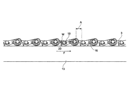
position according to Figure 9, an angle W between a
straight line 19 formed parallel to the conveying
direction F and thus to the endless carrier 3, and a
straight line 20 formed by the longitudinal extent of a
flap unit is virtually 0 (Figure 9). As a result of the
spacing apart of the positioning means 13 from the
endless carrier or the axis of rotation of the stationary
screening bars 4, the flap units can flap open under
gravity and optionally loaded by mixture to be screened
to a larger angle W and continue to rest on the guide
surface 16 (Figure 10). The greater spacing apart of the
positioning means 13 from the axis of rotation of the
respective stationary screening bar of a respective flap
unit has the result, in the horizontal orientation,
illustrated in Figure 11, of the screening belt 2, that
the joint parts 12 no longer rest on the guide surface
16 and the flap parts are pivoted open to a maximum.
Depending on the symmetry of the flap unit, the angle W
taken up for this is virtually 90 , but at least
preferably between 80 and 100 . In order to avoid
gravity-related overturning of the flap units in the
region of the deflection of the endless carriers 3 or of
the screening belt 2, a roller that is conventionally
used as a guide unit 21 in the form of a haulm feed-in
roller and is formed preferably in a wider manner than
the endless carrier may be present in the deflection
region (Figure 2).
A flap unit according to the invention that is an
alternative to the flap unit according to Figure 6 has a
joint part 12, which, in order to pivotably fix the joint
part in particular to a screening bar connected fixedly
Date Recue/Date Received 2020-04-15
CA 03079104 2020-04-15
- 22 -
to an endless carrier, has a sliding and/or latching
element 22, via which the fastening and removal of a flap
unit takes place as quickly and easily as possible
(Figures 12a-c). Rather than the screw connections of the
joint part 12 according to Figure 6, this joint part, and
also the joint part according to Figures 13a-c, is
provided with a latching and/or sliding element, which
is introduced into a main part 23 of the joint part either
at the end (Figure 12a) or at the side (Figure 13a) and
is latched (Figure 12b) or secured (Figure 13b) there via
undercuts 24.
The respective latching and/or sliding element 22 is made
preferably of a harder material than the rest of the
joint part 12 in the region of contact with a screening
bar, such that the latching and/or sliding element 22
takes up the main forces that act on the flap unit and
transfers them to the generally stationary screening bar,
on which the flap unit is arranged.
The latching and/or sliding element 22 forms, for the
preferably stationary screening bar, together with the
rest of the joint part 12, a cross-sectionally round
bearing seat, which can be seen in Figure 12b and Figure
13b. For this purpose, the latching and/or sliding
elements 22 of the exemplary embodiments in Figures 12
and 13 are provided with a cross-sectionally half-shell-
shaped receptacle 24, the inner surface of which jointly
forms, with a correspondingly shaped receptacle 25 of the
main part 23, the bearing seat for the respective
screening bar.
In a further exemplary embodiment according to the
invention of a screening belt unit, the latter is
provided with two guide surfaces 16, which, in the cross
section in Figure 14 and as seen in the conveying
direction, are angled at an angle y to an underlying
Date Recue/Date Received 2020-04-15
CA 03079104 2020-04-15
- 23 -
surface and configured in a manner dropping towards the
middle M of the screening belt unit. As a result, less
undesired extraneous material in the form of earth or
clods can be deposited on the guide surfaces, and at the
same time the flap unit is centred on the outer surface
of the joint parts 12 by way of the correspondingly
adapted joint part guide surfaces 16.1 and by way of
joint part guide surfaces 16.1 that are positioned in an
inclined manner in a complementary manner.
Date Recue/Date Received 2020-04-15