Note: Descriptions are shown in the official language in which they were submitted.
CA 03079165 2020-04-15
G1904
PRODUCTION METHOD FOR ALL-SOLID-STATE BATTERY
TECHNICAL FIELD
[0001]
The present invention relates to a method for producing an all-solid-state
battery.
BACKGROUND ART
[0002]
Recently, a demand for lithium ion secondary batteries has been increased in
applications including portable information terminals, portable electronic
equipments,
electric vehicles, hybrid electric vehicles and stationary power storage
systems.
However, currently, a flammable organic solvent is used as an electrolytic
solution in
lithium ion secondary batteries, and a strong exterior is required so that an
organic solvent
does not leak out. Further, for example, in the case of portable personal
computers, it is
necessary to employ a structure against a risk at the time when an
electrolytic solution
leaks out. Thus, there is a limitation on structures of devices.
[0003]
Moreover, the range of applications thereof has been widened to movable bodies
such as vehicles and aircrafts, and a high capacity is desired for stationary
lithium ion
secondary batteries. Under such circumstances, importance tends to be placed
on safety
more than before, and efforts are concentrated on the development of an all-
solid-state
lithium ion secondary battery in which none of toxic substances such as
organic solvents
is used.
For example, use of an oxide, phosphate compound, organic polymer, sulfide,
complex hydride or the like as a solid electrolyte in an all-solid-state
lithium ion
secondary battery has been examined.
[0004]
All-solid-state batteries are broadly classified into the thin film type and
the bulk
type. In the case of the thin film type, interface bonding is ideally formed
by utilizing
gas phase film formation, but the electrode layer is thin (several gm), the
electrode area
is small, the amount of energy which can be stored per cell is small, and the
cost is high.
Therefore, it is inappropriate as a battery for large electrical storage
devices or electric
vehicles, wherein a large amount of energy must be stored. Meanwhile, in the
case of
the bulk type, the thickness of the electrode layer can be adjusted to be
several tens um
to 100 um, and it is possible to prepare an all-solid-state battery having a
high energy
density.
1
Date Recue/Date Received 2020-04-15
CA 03079165 2020-04-15
G1904
[0005]
Among solid electrolytes, a sulfide solid electrolyte and a complex hydride
have
characteristics that they have high ion conductivity and are relatively soft,
and that
therefore it is easy to form the interface between solids. They are stable
with respect to
metal lithium and have been developed as practical solid electrolytes.
[0006]
However, in methods for producing all-solid-state batteries using these solid
electrolytes, all-solid-state batteries are prepared by techniques using
pressing that
requires a high pressure, and for this reason, the production of large
electrodes is limited,
and there is a problem of difficulty in interface bonding. Further, since the
sulfide solid
electrolyte and the complex hydride solid electrolyte are unstable against
water, special
environments such as an inert gas atmosphere or a dry room with a very low dew
point
are required, and for this reason, it has been desired that all-solid-state
batteries can be
produced with an apparatus which enables preparation in a small space.
[0007]
With respect to the problems, it is disclosed that a surface of a positive
electrode
layer and a surface of a negative electrode layer to be faced to each other
are coated with
a solid electrolyte solution and bonded together, thereby forming a good
interface with a
low pressing pressure (Patent Document 1). However, the positive electrode
layer and
negative electrode layer themselves must be formed with a high pressing
pressure, and
there is a problem that when the sulfide solid electrolyte is dissolved with
an alcohol
solvent, the sulfide solid electrolyte is gradually decomposed to generate
hydrogen sulfide.
PRIOR ART DOCUMENTS
PA! ________________________ ENT DOCUMENTS
[0008]
Patent Document 1: Japanese Laid-Open Patent Publication No. 2015-2080
SUMMARY OF THE INVENTION
PROBLEMS TO BE SOLVED BY THE INVENTION
[0009]
Under such circumstances, it is desired to provide a method for producing an
all-
solid-state battery having excellent productivity.
2
Date Recue/Date Received 2020-04-15
CA 03079165 2020-04-15
G1904
MEANS FOR SOLVING THE PROBLEMS
[0010]
The present inventors diligently made researches in consideration of the above-
described problem and obtained a finding that a good electrode layer filled
with a solid
electrolyte for all-solid-state batteries can be formed by impregnating an
electrode layer
for lithium ion batteries permeable to an electrolyte with a solid electrolyte
solution,
followed by removing a solvent to cause the solid electrolyte to precipitate.
In addition,
the present inventors obtained an unexpected finding that an all-solid-state
battery having
very high productivity and not requiring high press forming can be produced by
applying
the solid electrolyte solution to the electrode layer filled with the solid
electrolyte and
drying it to form a solid electrolyte and by bonding two electrode sheets
obtained.
[0011]
Specifically, the present invention is as described below.
<1> A method for producing an all-solid-state battery having a solid
electrolyte layer
between a positive electrode layer and a negative electrode layer, the method
comprising:
a step of coating or impregnating at least one of the positive electrode layer
and
the negative electrode layer with a solid electrolyte solution obtained by
dissolving a
boron hydride compound serving as a solid electrolyte in a solvent; and
a step of removing the solvent from the coated or impregnated solid
electrolyte
solution and causing the solid electrolyte to precipitate on at least one of
the positive
electrode layer and the negative electrode layer.
<2> The method according to item <1>, wherein the step of causing the solid
electrolyte
to precipitate comprises forming the solid electrolyte layer on at least one
of the positive
electrode layer and the negative electrode layer.
<3> The method according to item <I>, which comprises a step of further
coating at least
one of the positive electrode layer and the negative electrode layer on which
the solid
electrolyte is caused to precipitate with the solid electrolyte solution,
removing the
solvent from the solid electrolyte solution and forming the solid electrolyte
layer on at
least one of the positive electrode layer and the negative electrode layer.
<4> The method according to item <1>, which comprises a step of preparing the
solid
electrolyte layer by impregnating a support with the solid electrolyte
solution and
removing the solvent from the solid electrolyte solution.
<5> The method according to any one of items <2> to <4>, which comprises a
step of
bonding the positive electrode layer to the negative electrode layer in a
manner such that
the solid electrolyte layer is positioned between the positive electrode layer
and the
negative electrode layer.
3
Date Recue/Date Received 2020-04-15
CA 03079165 2020-04-15
G1904
<6> The method according to item <5>, wherein the pressing pressure in the
step of
bonding the positive electrode layer to the negative electrode layer is 0.001
MPa to 10
MPa.
<7> The method according to item <2> or <3>, wherein at least one of the
positive
electrode layer and the negative electrode layer on which the solid
electrolyte layer is
formed is formed without pressing.
<8> The method according to any one of items <1> to <7>, wherein the boron
hydride
compound comprises at least one selected from the group consisting of LiBH4,
an LiBH4-
Li-based material, 3LiBH4-LiI, an LiBH4-P2S5-based material, 9LiBRI-P2S5, an
LiBH4-
P214-based material, 9LiBH4-P214, 85LiBH4-15P214, Li2B12H12, L0101410,
LiCBilF112 and
LiCB9Hio.
<9> The method according to item <8>, wherein the boron hydride compound
comprises
LiBH4.
<10> The method according to any one of items <1> to <9>, wherein the solvent
comprises at least one selected from the group consisting of H20, an alcohol-
based
solvent, an ether-based solvent and a nitrile-based solvent.
<11> The method according to item <10>, wherein the solvent comprises at least
one
selected from the group consisting of tetrahydrofuran and acetonitrile.
<12> The method according to any one of items <1> to <11>, wherein the
positive
electrode layer contains a positive electrode active material, and wherein the
electric
potential of the positive electrode active material with reference to lithium
is 3.0 V or less.
<13> The method according to any one of items <1> to <12>, wherein the
positive
electrode layer contains a sulfur-based positive electrode active material.
<14> The method according to any one of items <1> to <13>, wherein the
negative
electrode layer contains at least one selected from the group consisting of
silicon, tin, a
silicon-containing compound and a tin-containing compound as a negative
electrode
active material.
<15> The method according to item <14>, wherein SiO is contained as the
negative
electrode active material.
<16> A method for producing an all-solid-state battery having a solid
electrolyte layer
between a positive electrode layer and a negative electrode layer, the method
comprising:
a step of coating or impregnating at least one of the positive electrode layer
and
the negative electrode layer with a molten salt obtained by melting a boron
hydride
compound serving as a solid electrolyte; and
a step of cooling the molten salt and causing the solid electrolyte to
precipitate
on at least one of the positive electrode layer and the negative electrode
layer.
4
Date Recue/Date Received 2020-04-15
CA 03079165 2020-04-15
G1904
ADVANTAGEOUS EFFECT OF THE INVENTION
[0012]
According to the present invention, it is possible to provide a method for
producing an all-solid-state battery. Further, according to the present
invention, since a
high pressing pressure is not required, it is possible to provide a method for
producing an
all-solid-state battery, which has high productivity and can be applied to
mass production.
BRIEF DESCRIPTION OF THE DRAWINGS
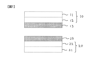
[0013]
FIG. 1 is a schematic view showing an example of the layer structure of the
all-
solid-state battery of the present invention.
FIG. 2 shows charging and discharging curves of the all-solid-state battery
prepared in Example 1.
FIG. 3 shows cycle characteristics of the all-solid-state battery prepared in
Example 2.
EMBODIMENTS FOR CARRYING OUT THE INVENTION
[0014]
Hereinafter, the method for producing the all-solid-state battery of the
present
invention will be specifically described. Note that
materials, constitutions, etc.
described below do not limit the present invention and can be modified
variously within
the range of the gist of the present invention. In this specification, when a
numerical
range is shown using "-", the range includes numerical values at the both
sides of "-".
[0015]
<Electrode sheet>
An example of the layer structure of the all-solid-state battery of the
present
invention will be described using Figure 1.
An electrode sheet 10 to be used in the present invention is also referred to
as a
"positive electrode sheet" and has a positive electrode layer 12 on a current
collector 11.
On the positive electrode layer 12, a solid electrolyte layer 13 is formed.
An electrode sheet 20 to be used in the present invention is also referred to
as a
"negative electrode sheet" and has a negative electrode layer 22 on a current
collector 21.
On the negative electrode layer 22, a solid electrolyte layer 23 is formed.
Further, the positive electrode layer 12 is bonded to the negative electrode
layer
22 in a manner such that the solid electrolyte layers 13 and 23 are positioned
between the
Date Recue/Date Received 2020-04-15
CA 03079165 2020-04-15
G1904
positive electrode layer 12 and the negative electrode layer 22, thereby
preparing an all-
solid-state battery according to one embodiment of the present invention.
Note that the positive electrode layer and the negative electrode layer are
collectively referred to as the electrode layer.
As the electrode layer to be used in the present invention, it is possible to
use an
electrode layer for lithium-ion batteries using an electrolyte. As described
above, in the
structure of a general electrode sheet, an electrode layer is formed on a
current collector.
The positive electrode layer is usually formed with a positive electrode
active material, a
binder and a conduction assisting agent, and the negative electrode layer is
usually formed
with a negative electrode active material, a binder and a conduction assisting
agent.
These electrode layers have a void and can be impregnated with an electrolyte.
Note
that it is possible to employ a constitution in which a metal foil or alloy
foil is used for
either the positive electrode layer or the negative electrode layer and the
electrode sheet
produced in the present invention is used for the other electrode.
As the current collector, in general, a stainless steel foil or aluminum foil
is used
for the positive electrode layer, and a stainless steel foil or copper foil is
used for the
negative electrode layer. Note that a current collector whose surface is
carbon-coated
can also be used.
[0016]
The positive electrode active material to be contained in the positive
electrode
layer is not particularly limited as long as it is a material which can
release lithium ions
at the time of charging and can absorb lithium ions at the time of
discharging. Examples
thereof include a metal oxide having a transition metal, a sulfur-based
positive electrode
active material, an organic positive electrode active material, and FeF3 and
VF3 utilizing
a conversion reaction. In the present invention, the electric potential of the
positive
electrode active material with reference to lithium is preferably 3.0 V or
less because in
this case, a reaction between an active material and a boron hydride compound-
based
solid electrolyte interface is suppressed, resulting in smaller interface
resistance. The
electric potential of the positive electrode active material with reference to
lithium is more
preferably 1.0-2.7 V.
[0017]
As the metal oxide having a transition metal, it is possible to use particles
or a
thin film of a metal oxide containing lithium and at least one of Mn, Co, Ni,
Fe, Cr and
V that are transition metals. Specific examples thereof include, but are not
particularly
limited to, LiCo02, LiCo204, LiMn02, LiMn204, LiMnCo04, Li2MnCo04,
LiNio8Coo15A100502, LiNio.5Mno 502, Li2NiMn308, LiV02, LiV303, LiCr02,
LiFePO4,
6
Date Recue/Date Received 2020-04-15
CA 03079165 2020-04-15
G1904
LiCoPO4, LiMnPO4, LiV0PO4, LiNi02, LiNi204, LiNii13CoiaMn1t302, Li2FeSiO4,
Li2MnSiO4 and LiFeB03. Further, Fe2O3, Cr308, V205, Mn02, etc. can also be
used.
Among them, LiCo02, LiMn02, LiMn204, LiNio8Coo i5Alo 0502, LiNio5Mno502,
Li2NiMn308, LiFePO4, LiCoPO4, LiMnPO4, LiV0PO4, LiNi02 and LiNi1i3C01/3Mn1/302
are preferred.
Regarding these positive electrode active materials, it is possible to provide
a
coating layer to the particles or thin film of the positive electrode active
materials for the
purpose of suppressing a reaction with a solid electrolyte. Examples of the
coating layer
include LiNb03, Li4Ti5012, LiTa03, LiNb03, LiA102, Li2Zr03, Li2W04, Li2TiO3,
Li2B407, Li3PO4, Li2Mo04 and LiB02.
[0018]
Specific examples of the sulfur-based positive electrode active material
include,
but are not particularly limited to, S, a sulfur-carbon composite, TiS2, TiS3,
TiS4, NiS,
NiS2, CuS, FeS2, Li2S, MoS3, a sulfur-modified polyacrylonitrile, rubeanic
acid
(dithiooxamide) and a disulfide compound. Among them, TiS2, TiS3, TiS4, NiS,
NiS2,
FeS2, Li2S, MoS3, a sulfur-modified polyacrylonitrile, a sulfur-carbon
composite and
rubeanic acid (dithiooxamide) are preferred.
[0019]
Specific examples of the organic positive electrode active material include,
but
are not particularly limited to, a radical compound typified by 2,2,6,6-
tetramethylpiperidinoxy1-4-ylmethacrylate and polytetramethylpiperidinoxy
vinyl ether,
a quinone compound, a radialene compound, tetracyanoquinodimethane and
phenazine
oxide. Among them, a radical compound and a quinone compound are preferred
because these compounds have a large theoretical capacity and can maintain a
discharge
capacity at a relatively good level.
[0020]
As the above-described positive electrode active material, an optimum material
may be selected depending on the type of the solid electrolyte for
impregnation. For
example, when using LiBI-14 having low oxidation resistance as the main
component of
the solid electrolyte, it is preferred to use a sulfur-based positive
electrode active material
which is an active material having a low equilibrium potential. As the sulfur-
based
positive electrode active material, for example, a sulfur-modified
polyacrylonitrile
typified by the compound described in W02010/044437 and a sulfur-carbon
composite
typified by those described in W02015/030053, Japanese Laid-Open Patent
Publication
No. 2015-92449 and W02015/030053 can be used. When using a higher-order borane
compound having high withstand voltage such as Li2B12H12 as the main component
of
7
Date Recue/Date Received 2020-04-15
CA 03079165 2020-04-15
G1904
the solid electrolyte, in addition to the above-described sulfur-based
positive electrode
active material, a metal oxide having a transition metal which is an active
material having
a high equilibrium potential can also be used. When using a positive electrode
active
material having a high equilibrium potential, a battery voltage per cell can
be increased.
[0021]
As the negative electrode active material to be contained in the negative
electrode layer, for example, a metal active material and a carbon-based
active material
can be used. Examples of the metal active material include Li4Tis012, Li, In,
Al, Si, SiO,
Sn and alloys of these metals. Examples of the carbon-based active material
include
mesocarbon microbeads (MCMB), a highly oriented graphite (HOPG), a hard carbon
and
a soft carbon. In particular, it is preferred to use an active material having
a lower
equilibrium potential as the negative electrode because the energy density of
the battery
is improved to increase the operating voltage. Examples of such negative
electrode
active materials include Li, a carbon-based active material, Si and SiO.
[0022]
The binder to be used for the positive electrode layer is not particularly
limited,
but for example, a polyimide-based material, an acrylic material,
polysiloxane,
polyalkylene glycol, polyvinylidene fluoride (PVdF), polytetrafluoroethylene
(PTFE),
ethylene-vinyl alcohol copolymer (EVOH), etc. can be used. According to need,
a
thickener such as carboxymethyl cellulose (CMC) can also be used.
The binder to be used for the negative electrode layer is not particularly
limited,
but for example, a polyimide-based material, polysiloxane, polyalkylene
glycol,
polyvinylidene fluoride (PVdF), polytetrafluoroethylene (PTFE), styrene-
butadiene
rubber (SBR), an acrylic material, etc. can be used. According to need, a
thickener such
as carboxymethyl cellulose (CMC) can also be used.
[0023]
The conduction assisting agent to be used for the electrode layer is not
particularly limited as long as it has desired conductivity. Examples thereof
include a
conduction assisting agent made of a carbon material. Specific examples
thereof
include carbon black, acetylene black, Ketjen black and carbon fiber.
[0024]
As the method for preparing the electrode sheet, a publicly-known method can
be used. For example, the positive electrode active material or negative
electrode active
material is mixed with the binder, the conduction assisting agent and an
organic solvent
to prepare a coating solution. The current collector is coated with the
coating solution
using the doctor blade method, spin coating method, spray coating method or
the like,
8
Date Recue/Date Received 2020-04-15
CA 03079165 2020-04-15
G1904
followed by drying, thereby preparing the electrode sheet, wherein the
electrode layer is
formed on the current collector.
[0025]
<Lithium doping>
In the case where none of the positive electrode layer and the negative
electrode
layer contains Li as the active material, for example, in the case where the
sulfur-based
positive electrode active material is used for the positive electrode layer
and Si, SiO or
the carbon-based active material is used for negative electrode layer, one of
the active
materials must be lithium-doped. Lithium doping is carried out, for example,
by
assembling an electrolyte-based battery as described in W02015/152214. When
producing an all-solid-state battery using an electrolyte-based electrode
sheet as in the
case of the present invention, lithium doping can be carried out according to
an existing
method. The interfaces between the positive electrode layer, the solid
electrolyte layer
and the negative electrode layer in the all-solid-state battery must be firmly
bonded. It
is extremely difficult to carry out lithium doping in the form of the all-
solid-state battery
and to disassemble the battery to take out each electrode sheet. Therefore, in
the case
where the all-solid-state battery is produced using a combination of active
materials,
wherein none of the active materials of the positive electrode layer and the
negative
electrode layer contains Li, a production method utilizing an electrode sheet
usable in the
electrolyte system is significantly advantageous.
As the method of lithium doping, a publicly-known method can be used. For
example, lithium doping may be carried out according to an electrochemical
method in
which a metal lithium foil is used for a counter electrode to prepare a
battery, or a chemical
method in which a metal hydride such as metal lithium, alkyllithium, LiA1H4
and LiBH4
is directly brought into contact with the electrode sheet to perform a
reaction. When
lithium doping is carried out according to the chemical method, it can be
applied to the
electrode sheet or the active material. Among these techniques, an
electrochemical
technique is more excellent because the amount of lithium doping can be
comprehended
by measuring the amount of a current flowed or the electric potential of the
lithium-doped
electrode layer.
[0026]
<Solid electrolyte solution>
As the solid electrolyte solution to be used in the present invention, a
product
obtained by dissolving a boron hydride compound serving as the solid
electrolyte in a
solvent can be used.
As the solid electrolyte to be dissolved in the solvent, the boron hydride
9
Date Recue/Date Received 2020-04-15
CA 03079165 2020-04-15
G1904
compound can be used without particular limitation, but it is preferably a Li-
containing
boron hydride compound, and examples thereof include LiBH4, a LiBH4-LiI-based
material, 3LiBRI-Lif, a LiBH4-P2S5-based material, 9LiBH4-P2S5, a LiBH4-P214-
based
material, 9LiBH4-P214, 85LiBH4-15P214, Li2B12H12, Li2B1oHio, LiCBIIH12 and
LiCB9Hio.
The LiBH4-LiI-based material means a solid solution with a molar ratio of
LiBH4/LiI=0.8-5. The LiBH4-P2S5-based material means a crystal synthesized
with a
feed molar ratio of LiBH4/P2S5=5.6-49. The LiBH4-P214-based material means a
crystal
synthesized with a feed molar ratio of LiBH4/P2I4=4-99.
[0027]
The solvent is not particularly limited as long as the solid electrolyte can
be
dissolved therein, but it is preferably a material that does not react with
the solid
electrolyte. For LiBH4-based materials, an ether-based solvent such as
tetrahydrofuran,
2-methyltetrahydrofuran, 1,2-dimethoxyethane and diethylene glycol dimethyl
ether; a
nitrile-based solvent such as propanenitrile and acetonitrile; and an amide-
based solvent
such as N,N-dimethylformamide and N,N-dimethylacetamide are more preferred,
and
these materials may be used solely or in combination. Even more preferred are
tetrahydrofuran, 2-methyltetrahydrofuran, 1,2-dimethoxyethane, diethylene
glycol
dimethyl ether and acetonitrile, and particularly preferred are
tetrahydrofuran and
acetonitrile.
For higher-order boron hydride compounds such as Li2B12H12, it is possible to
use various materials including: H20; an alcohol-based solvent such as
methanol, ethanol,
propanol and butanol; an ether-based solvent such as tetrahydrofuran, 2-
methyltetrahydrofuran, 1,2-dimethoxyethane and diethylene glycol dimethyl
ether;
acetonitrile; an acid ester-based solvent such as ethyl acetate and methyl
acetate; an
amide-based solvent such as N,N-dimethylformamide and N,N-dimethylacetamide;
and
a ketone-based solvent, and these materials may be used solely or in
combination.
Among them, H20, an alcohol-based solvent and acetonitrile are preferred in
consideration of the solubility, viscosity, evaporation rate, safety of
solvent and
suppressing side reactions.
When LiBH4 is contained, since dissolution is easily performed by H20, it is
preferred to sufficiently remove the moisture in the solvent. The moisture
concentration
is preferably 50 ppm or less, and more preferably 15 ppm or less. Meanwhile,
since the
higher-order boron hydride compound is stable even in H20 at room temperature,
it can
be used even when the moisture content in the solvent is relatively high.
The concentration of the solid electrolyte in the solid electrolyte solution
is
generally adjusted to 1-40 wt% so that the optimum viscosity can be obtained
at the time
Date Recue/Date Received 2020-04-15
CA 03079165 2020-04-15
G1904
of impregnation later, though the optimum value varies depending on the types
of the
solid electrolyte and the solvent. When the concentration is lower than this
range, the
efficiency of precipitation of the solid electrolyte is deteriorated. When
the
concentration is higher, the viscosity increases, and due to this,
impregnation to the
bottoms of pores may become more difficult. The concentration of the solid
electrolyte
in the solid electrolyte solution is preferably 3-25 wt%.
[0028]
<Solid electrolyte molten salt>
In the present invention, it is possible to use a molten salt obtained by
melting a
boron hydride compound having a low melting point instead of the above-
described solid
electrolyte solution. As a boron hydride compound having a relatively low
melting
point, a Li-containing boron hydride compound is preferred, and examples
thereof
include LiBH4-LiNH2 which has a melting point of 95-105 C. The range of the
melting
point is preferably 80-250 C. When the range is lower than that, the solid
electrolyte is
melted due to increase in the battery temperature, and it may cause a short
circuit. When
the temperature is higher than the range, a high-temperature molten salt may
react with
the active material of the electrode layer, the carbon material and the
current collector.
At the time of impregnation into the electrode layer, a solid electrolyte
solution having a
low viscosity more easily enters to the bottoms of pores of the electrode
layer. For this
reason, it is preferred to use the solid electrolyte solution whose viscosity
can be easily
adjusted by changing its concentration.
[0029]
<Impregnation with solid electrolyte solution or solid electrolyte molten
salt>
As the method for impregnating the electrode sheet with the solid electrolyte
solution, a publicly-known method for impregnating an electrode sheet with an
electrolyte
can be used. In particular, for impregnation to the bottoms of pores of the
electrode layer,
vacuum impregnation is preferred. Further, when heating, the viscosity of the
solution
is decreased, and therefore impregnation to the bottoms of pores can be
carried out more
efficiently.
As the method for impregnating the electrode sheet with the solid electrolyte
molten salt, impregnation is carried out in a heated state where the
temperature is equal
to or higher than the melting point of the solid electrolyte, and the
temperature range may
be 80-300 C. When impregnation is carried out at a temperature higher than
that, the
active material may react with the molten salt. Further, for impregnation to
the bottoms
of pores of the electrode layer, vacuum impregnation is preferred.
[0030]
11
Date Recue/Date Received 2020-04-15
CA 03079165 2020-04-15
G1904
<Precipitation of solid electrolyte to voids of electrode layer>
After the electrode layer is impregnated with the solid electrolyte solution,
the
solvent is removed to cause the solid electrolyte to precipitate, and voids of
the electrode
layer are densely filled with the solid electrolyte. In the case of
impregnation with the
solid electrolyte molten salt obtained by melting the solid electrolyte having
a low melting
point, the temperature is decreased to the melting point or lower to cause the
solid
electrolyte to precipitate. In the case of using the solid electrolyte
solution obtained by
dissolving the solid electrolyte in the solvent, the solvent is volatilized to
cause the solid
electrolyte to precipitate. It is preferred to perform heating in order to
promote
volatilization of the solvent. The temperature for heating varies depending on
the type
of the solvent, but it may be 50-200 C. When the solvent is volatilized at a
temperature
higher than this range, there is concern that the solid electrolyte may not
precipitate
densely due to occurring of a side reaction or foaming of the solvent.
Further, by heating
under an inert gas stream or under vacuum, volatilization of the solvent can
be promoted.
The electrode sheet filled with the solid electrolyte after drying is
subjected to
rolling, thereby more densifying the electrode layer. The method of rolling is
not
particularly limited, but it is preferred to use the roll pressing method
which is used for
preparing electrode sheets of lithium ion batteries. The roll pressing method
has high
continuous productivity, but the pressing pressure in this case is lower than
those of the
uniaxial pressing method and isostatic pressing method. The pressing pressure
in this
case is preferably 0.1-100 MPa, and more preferably 1-80 MPa. For forming
conventional all-solid-state batteries, very high pressing pressures are
required in order
to deform and densify powder itself, but in the present invention, since the
solid
electrolyte is formed densely in the voids of the electrode layer by causing
the solid
electrolyte to precipitate from the solid electrolyte solution, it is not
required to apply a
high pressing pressure such as 300 MPa that deforms particles. In the present
invention,
the purpose of rolling after drying is to fill small cracks generated by
expansion/shrinkage
due to thermal change and small voids generated at the time of volatilization
of the solvent,
and sufficient effects can be obtained by the roll pressing method.
Unlike Patent Document 1 (Japanese Laid-Open Patent Publication No. 2015-
2080), the present invention has the advantage that the positive electrode
layer and
negative electrode layer whose pores are filled with the solid electrolyte can
be formed
without pressing.
[0031]
<Formation of solid electrolyte layer>
The surface of the electrode layer whose pores are filled with the solid
electrolyte
12
Date Recue/Date Received 2020-04-15
CA 03079165 2020-04-15
G1904
is coated with the solid electrolyte solution described in <Solid electrolyte
solution>, and
then the solvent is removed to cause the solid electrolyte to precipitate,
thereby forming
the solid electrolyte layer. Alternatively, the surface of the electrode layer
whose pores
are filled with the solid electrolyte is coated with the solid electrolyte
molten salt
described in <Solid electrolyte molten salt>, and then the molten salt is
cooled to cause
the solid electrolyte to precipitate, thereby forming the solid electrolyte
layer. Coating
can be carried out according to a publicly-known method, and examples thereof
include
the doctor blade method, the spin coating method and the spray coating method.
Drying
can be carried out according to a method similar to that described in
<Precipitation of
solid electrolyte to voids of electrode layer>. By coating the surface of the
electrode
layer with the solid electrolyte solution or solid electrolyte molten salt at
the time of
<Impregnation with solid electrolyte solution or solid electrolyte molten
salt>,
<Precipitation of solid electrolyte to voids of electrode layer> and
<Formation of solid
electrolyte layer> can be carried out simultaneously.
When the solid electrolyte layer formed on the positive electrode sheet is too
thin,
a short circuit may be caused, and when the layer is too thick, the resistance
is increased.
From this viewpoint, the thickness of the solid electrolyte layer is
preferably 1-300 gm,
and more preferably 5-100 gm.
When the solid electrolyte layer formed on the negative electrode sheet is too
thin, a short circuit may be caused, and when the layer is too thick, the
resistance is
increased. From this viewpoint, the thickness of the solid electrolyte layer
is preferably
1-300 gm, and more preferably 5-100 gm.
[0032]
Further, the solid electrolyte layer can be formed independently. In this
case, a
support into which solutions can permeate is impregnated with the solid
electrolyte
solution, and the solvent is removed to cause the solid electrolyte to
precipitate. Since
the solid electrolyte layer plays a role as a separator between the positive
electrode layer
and the negative electrode layer, the support is required to have high
insulation properties,
and though there is no particular limitation, it is possible to use a
separator to be used for
electrolytes. Examples thereof include a glass fiber filter, a polyolefin-
based separator,
a cellulose-based separator and a non-woven fabric-based separator. Among
them,
preferred are a glass fiber filter and non-woven fabric, which have a high
ratio of voids
in the separator and high heat resistance. This is because, since the solid
electrolyte is
formed in void portions, the ratio of the solid electrolyte serving as the ion
conductor is
increased. Further, in the case of a polyolefin-based separator having the
shutdown
function, by heating at the time of <Precipitation of solid electrolyte to
voids of electrode
13
Date Recue/Date Received 2020-04-15
CA 03079165 2020-04-15
G1904
layer>, the shutdown function is actuated, and the number of voids in which
the solid
electrolyte precipitates may be more decreased. As the impregnation method and
the
method for precipitation of the solid electrolyte, methods similar to those
respectively
described in <Impregnation with solid electrolyte solution or solid
electrolyte molten
salt> and <Precipitation of solid electrolyte to voids of electrode layer> can
be conducted.
In such a manner, a solid electrolyte layer sheet can be prepared
independently. The
thickness of the solid electrolyte sheet is preferably 1-300 m, and more
preferably 5-100
pm.
After the solid electrolyte is precipitated by drying, the solid electrolyte
layer is
densified by rolling. The rolling method is not particularly limited, but it
is preferred to
employ the roll pressing method which has excellent productivity. Since the
solid
electrolyte layer obtained by causing the solid electrolyte to precipitate
from the solid
electrolyte solution is relatively dense and the boron hydride compound is
soft, the solid
electrolyte layer can be sufficiently densified by rolling with a low pressing
pressure.
The pressing pressure in this case is preferably 0.1-100 MPa, and more
preferably 1-80
MPa.
[0033]
<Preparation of all-solid-state battery>
The all-solid-state battery can be prepared by layering respective sheets,
followed by rolling.
In the present invention, it is preferred to include a step of bonding the
positive
electrode layer to the negative electrode layer in a manner such that the
solid electrolyte
layer is positioned between the positive electrode layer and the negative
electrode layer.
The pressing pressure for bonding the positive electrode layer to the negative
electrode
layer is preferably 0.0001-100 MPa, more preferably 0.0005-20 MPa, and
particularly
preferably 0.001-10 MPa.
As the combination of respective sheets, any of the following combinations can
be employed: (1) a sheet obtained by forming the solid electrolyte layer on
the positive
electrode sheet + the negative electrode sheet; (2) a sheet obtained by
forming the solid
electrolyte layer on the negative electrode sheet + the positive electrode
sheet; (3) a sheet
obtained by forming the solid electrolyte layer on the positive electrode
sheet + a sheet
obtained by forming the solid electrolyte layer on the negative electrode
sheet; and (4)
the positive electrode sheet + the solid electrolyte layer sheet + the
negative electrode
sheet. The boron hydride compound has an ability as a binder, and therefore
has a high
effect of bonding these sheets. As the rolling method, for example, the roll
pressing
method can be employed.
14
Date Recue/Date Received 2020-04-15
CA 03079165 2020-04-15
G1904
EXAMPLES
[0034]
Hereinafter, the embodiments of the present invention will be more
specifically
described by way of examples, but the embodiments are not limited to the
examples.
(Example 1)
<Method for producing sulfur-based positive electrode active material>
With 100 parts by weight of a high cis butadiene rubber (UBEPOL (registered
trademark) BR150L manufactured by Ube Industries, Ltd., cis-1,4 bond content:
98%),
1000 parts by weight of sulfur (colloidal sulfur manufactured by Tsurumi
Chemical
Industry Co., Ltd.), 25 parts by weight of a vulcanization accelerator (zinc
diethyldithiocarbamate: NOCCELER (registered trademark) EZ manufactured by
Ouchi
Shinko Chemical Industrial Co., Ltd.) and 20 parts by weight of acetylene
black (DENKA
BLACK manufactured by Denki Kagaku Kogyo K.K.) were blended, and the mixture
was kneaded using a kneading test apparatus. This was heated to 450 C under
argon
atmosphere at a temperature raising rate of 5 C/min, and after that, it was
kept at 450 C
for 2 hours and then naturally cooled. During this, sulfur was set to be under
a refluxed
condition, and a slight amount of argon was flowed in order to remove a gas
generated.
After that, it was kept at 250 C for 3 hours under vacuum conditions and the
remaining
sulfur was removed, thereby obtaining a sulfur-based positive electrode active
material.
[0035]
<Method for producing positive electrode slurry>
Weighing was carried out so that the weight ratio of the above-described
sulfur-
based positive electrode active material obtained: acetylene black: VGCF:
acrylic binder
became 87:2:8:3, water was moderately added to the mixture and it was kneaded
by a
kneading machine, thereby obtaining a positive electrode slurry. Note that
VGCF is a
registered trademark of Showa Denko K.K. and it is a vapor grown carbon fiber.
<Method for producing negative electrode slurry>
Weighing was carried out so that the weight ratio of SiO: acetylene black:
polyimide binder became 80:5:15, N-methylpyrrolidone was moderately added to
the
mixture and it was kneaded by a kneading machine, thereby obtaining a negative
electrode slurry.
[0036]
<Preparation of electrode sheets>
A current collector (carbon-coated aluminum foil having a thickness of 15
i_tm)
was coated with the above-described positive electrode slurry obtained, and a
current
Date Recue/Date Received 2020-04-15
CA 03079165 2020-04-15
G1904
collector (SUS foil having a thickness of 10 um) was coated with the above-
described
negative electrode slurry obtained, respectively using a desk-top coating
machine
(manufactured by Tester Sangyo Co., Ltd., FILM COATER: PI1210), and these were
preliminarily dried at 80 C for 10 minutes using a hot-air dryer. Each
electrode sheet
after preliminarily dried was put into a glass tube to perform evacuation, and
using a glass
tube oven, the positive electrode sheet was vacuum dried at 160 C for 12 hours
and the
negative electrode sheet was vacuum dried at 300 C for 12 hours. After that,
the
positive electrode sheet was punched into a disk shape having a diameter of 11
mm and
the negative electrode sheet was punched into a disk shape having a diameter
of 12 mm
to obtain electrode sheets. The capacity density of the positive electrode
sheet was 1.0
mAh/cm2, and the capacity density of the negative electrode sheet was 3.0
mAh/cm2.
[0037]
<Lithium doping to negative electrode sheet>
A CR2032 type coin cell was prepared by using the above-described negative
electrode sheet prepared as a test electrode, a metal lithium foil having a
diameter of 14
mm as a counter electrode, a glass fiber filter (manufactured by Advantech
Co., Ltd., GA-
100, thickness: 500 um) having a diameter of 16 mm as a separator and 1M LiPF6
ethylene carbonate/diethyl carbonate (=1/1, vol/vol) as an electrolyte. Note
that all the
operations were carried out in a dry room (room temperature: 20 C, room dew
point: -
65 C).
Next, the negative electrode sheet was lithium-doped using a charge/discharge
test apparatus. Discharge (Li insertion) was performed at 30 C with a current
of 0.3 mA
until the voltage became 0.001 V, and after a 10-minute pause, charge (Li
removal) was
performed with a current of 0.3 mA until the voltage became 1.0 V. After that,
discharge
(Li insertion) was performed again with a current of 0.3 mA until the voltage
became
0.001 V, and thus the negative electrode sheet was lithium-doped.
[0038]
<Formation of solid electrolyte layer>
The CR2032 type coin cell after lithium-doping was disassembled to take out
the
negative electrode sheet, and the surface of the electrode sheet was washed
with dimethyl
carbonate and then naturally dried. The surface of the electrode layer of each
electrode
sheet was coated with 3LiBH4-LiI/tetrahydrofuran solution (solid content: 25%
by weight,
hereinafter referred to as the "solid electrolyte solution"), it was put into
an acrylic
vacuum vessel to perform evacuation, and it was allowed to stand for 1 hour to
impregnate
the electrode layer with the solid electrolyte solution. After that, the
electrode sheet was
taken out from the acrylic vacuum vessel and preliminarily dried on a hot
plate at 60 C
16
Date Recue/Date Received 2020-04-15
CA 03079165 2020-04-15
G1904
for 2 hours. Note that all the operations were carried out in a dry room (room
temperature: 20 C, room dew point: -65 C).
Each electrode sheet after preliminarily dried was put into a glass tube, and
using
a glass tube oven, it was vacuum dried at 80 C for 15 hours. After that, in
the dry room,
the electrode sheet was taken out from the glass tube, and it was made smooth
by cold
pressing under 2 MPa using a uniaxial pressing machine, thereby obtaining each
electrode
sheet, wherein the solid electrolyte layer was formed in the inside and on the
surface of
the electrode layer.
The weight and the thickness of the solid electrolyte layer formed in each
electrode sheet are shown in Table 1. The weight means the total weight of the
solid
electrolyte formed in the inside and on the surface of the electrode sheet,
and the thickness
means the thickness of the solid electrolyte layer formed on the surface of
the electrode
sheet.
[0039]
Table 1: Weight and thickness of solid electrolyte formed in each electrode
sheet
Solid electrolyte layer
Electrodes
Thickness Weight
Sulfur-based rubber positive electrode 44 inn 5.8 mg/cm2
SiO negative electrode 82 }trn 10.9 mg/cm2
[0040]
<Preparation of all-solid-state battery>
A CR2032 type coin cell was prepared by combining the positive electrode sheet
and the negative electrode sheet obtained above. Specifically, the sulfur-
based positive
electrode sheet and the SiO negative electrode sheet were layered in a manner
such that
the electrode layer surface of the positive electrode sheet and the electrode
layer surface
of the negative electrode sheet were opposed to each other. At the time of
layering, the
electrode sheets were successfully bonded together only by the pressure of a
disc spring
set in the coin cell without particular pressing.
[0041]
<Charge and discharge test>
Using the obtained all-solid-state battery, a constant current charge and
discharge
test was conducted with an environmental temperature of 90 C, a
charge/discharge
current of 0.1 mA and an operating voltage range of 0.5-2.5 V. The discharge
capacity
of the first time was 377 mAh/g (converted to the capacity per weight of the
positive
electrode sheet), and the charge capacity was 173 mAh/g (converted to the
capacity per
weight of the positive electrode sheet). Charging and discharging curves of
the prepared
17
Date Recue/Date Received 2020-04-15
CA 03079165 2020-04-15
G1904
all-solid-state battery were shown in Figure 2. It is understood from Figure 2
that the
prepared all-solid-state battery can perform charge/discharge stably in the
second cycle
or later.
[0042]
(Example 2)
<Method for producing positive electrode slurry>
Weighing was carried out so that the weight ratio of the sulfur-based positive
electrode active material obtained in Example 1: acetylene black: acrylic
binder became
90:5:5, water was moderately added to the mixture and it was kneaded by a
kneading
machine, thereby obtaining a positive electrode slurry.
<Method for producing negative electrode slurry>
Weighing was carried out so that the weight ratio of SiO: acetylene black:
VGCF:
polyimide binder became 77:4:1:18, N-methylpyrrolidone was moderately added to
the
mixture and it was kneaded by a kneading machine, thereby obtaining a negative
electrode slurry. Note that VGCF is a registered trademark of Showa Denko K.K.
and
it is a vapor grown carbon fiber.
[0043]
<Preparation of electrode sheets>
A current collector (carbon-coated aluminum foil having a thickness of 15 m)
was coated with the above-described positive electrode slurry obtained, and a
current
collector (SUS foil having a thickness of 10 um) was coated with the above-
described
negative electrode slurry obtained, respectively using a desk-top coating
machine
(manufactured by Tester Sangyo Co., Ltd., FILM COATER: PI1210), and these were
preliminarily dried at 80 C for 10 minutes using a hot-air dryer. Each
electrode sheet
after preliminarily dried was put into a glass tube to perform evacuation, and
using a glass
tube oven, the positive electrode sheet was vacuum dried at 150 C for 10 hours
and the
negative electrode sheet was vacuum dried at 300 C for 10 hours. After that,
the
positive electrode sheet was punched into a disk shape having a diameter of 11
mm and
the negative electrode sheet was punched into a disk shape having a diameter
of 11 mm
to obtain electrode sheets. The capacity density of the positive electrode
sheet was 0.51
mAh/cm2, and the capacity density of the negative electrode sheet was 1.0
mAh/cm2.
[0044]
<Lithium doping to negative electrode sheet>
A CR2032 type coin cell was prepared by using the above-described negative
electrode sheet prepared as a test electrode, a metal lithium foil having a
diameter of 14
mm as a counter electrode, a glass fiber filter (manufactured by Advantech
Co., Ltd., GA-
18
Date Recue/Date Received 2020-04-15
CA 03079165 2020-04-15
G1904
100, thickness: 500 inn) having a diameter of 16 mm as a separator and 1M
LiPF6
ethylene carbonate/diethyl carbonate (=1/1, vol/vol) as an electrolyte. Note
that all the
operations were carried out in a dry room (room temperature: 20 C, room dew
point: -
65 C).
Next, the negative electrode sheet was lithium-doped using a charge/discharge
test apparatus. Discharge (Li insertion) was performed at 30 C with a current
of 0.3 mA
until the voltage became 0.001 V, and after a 10-minute pause, charge (Li
removal) was
performed with a current of 0.3 mA until the voltage became 1.0 V. After that,
discharge
(Li insertion) was performed again with a current of 0.3 mA until the voltage
became
0.001 V, and thus the negative electrode sheet was lithium-doped.
[0045]
<Formation of solid electrolyte layer>
The CR2032 type coin cell after lithium-doping was disassembled to take out
the
negative electrode sheet, and the surface of the electrode sheet was washed
with dimethyl
carbonate and then naturally dried. The surface of the electrode layer of each
electrode
sheet was coated with 3LiBH4-LiI/tetrahydrofuran solution (solid content: 25%
by weight,
hereinafter referred to as the "solid electrolyte solution"), it was put into
an acrylic
vacuum vessel to perform evacuation, and it was allowed to stand for 1 hour to
impregnate
the electrode layer with the solid electrolyte solution. After that, the
electrode sheet was
taken out from the acrylic vacuum vessel and preliminarily dried on a hot
plate at 60 C
for 2 hours. Note that all the operations were carried out in a dry room (room
temperature: 20 C, room dew point: -65 C).
Each electrode sheet after preliminarily dried was put into a glass tube, and
using
a glass tube oven, it was vacuum dried at 150 C for 10 hours. After that, in
the dry room,
the electrode sheet was taken out from the glass tube, and it was made smooth
by cold
pressing under 2 MPa using a uniaxial pressing machine, thereby obtaining each
electrode
sheet, wherein the solid electrolyte layer was formed in the inside and on the
surface of
the electrode layer.
The weight and the thickness of the solid electrolyte layer formed in each
electrode sheet are shown in Table 2. The weight means the total weight of the
solid
electrolyte formed in the inside and on the surface of the electrode sheet,
and the thickness
means the thickness of the solid electrolyte layer formed on the surface of
the electrode
sheet.
[0046]
19
Date Recue/Date Received 2020-04-15
CA 03079165 2020-04-15
G1904
Table 2: Weight and thickness of solid electrolyte formed in each electrode
sheet
Solid electrolyte
Electrodes
Thickness Weight
Sulfur-based rubber positive electrode 34 p.m 3.94 mg/cm2
SiO negative electrode 42 gm 3.79 mg/cm2
[0047]
<Preparation of all-solid-state battery>
A CR2032 type coin cell was prepared by combining the positive electrode sheet
and the negative electrode sheet obtained above. Specifically, the sulfur-
based positive
electrode sheet and the SiO negative electrode sheet were layered in a manner
such that
the electrode layer surface of the positive electrode sheet and the electrode
layer surface
of the negative electrode sheet were opposed to each other, and cold pressing
was carried
out under 26 MPa using a uniaxial pressing machine. The obtained sheet was put
into
the CR2032 type coin cell, thereby preparing an all-solid-state battery.
[0048]
<Charge and discharge test>
Using the obtained all-solid-state battery, a constant current charge and
discharge
test was conducted with environmental temperatures of 60 C and 80 C, a
charge/discharge current of 0.1C-rate and an operating voltage range of 0.4-
3.0 V. Cycle
characteristics obtained by plotting discharge capacities relative to
respective cycles are
shown in Figure 3. It is understood from Figure 3 that the prepared all-solid-
state battery
successfully performed charge/discharge stably during the charge and discharge
test of
20 cycles.
EXPLANATIONS OF LETTERS OR NUMERALS
[0049]
electrode sheet (positive electrode sheet)
11 current collector
12 positive electrode layer
13 solid electrolyte layer
electrode sheet (negative electrode sheet)
21 current collector
22 negative electrode layer
23 solid electrolyte layer
Date Recue/Date Received 2020-04-15