Note: Descriptions are shown in the official language in which they were submitted.
LOCKING ASSEMBLY FOR AGRICULTURAL COMBINE HARVESTING HEAD
BACKGROUND
[0001] The present disclosure generally relates to agricultural combines.
More particularly,
the disclosure relates to a locking assembly for a flexible cutting bar of
agricultural harvesting
heads.
SUMMARY
[0002] In one aspect, a harvesting head is for an agricultural combine. The
agricultural
combine is supported on a surface. The harvesting head includes a frame
configured to move
between a raised position in which the frame is spaced from the surface and a
lowered position in
which the frame engages the surface. The harvesting head includes a support
ami coupled to the
frame. The support ami is configured to move between an unlocked state in
which the support
ami is pivotable relative to the frame and a locked state in which the support
aim is fixed relative
to the frame. The harvesting head includes cutting teeth supported by the
support ami relative to
the frame. The cutting teeth are configured to move relative to the support
aim in a reciprocating
motion along a longitudinal axis of the frame. The harvesting head includes a
gauge member
coupled to the frame. The gauge member is configured to engage the surface to
sense a height of
the frame relative to the surface. The harvesting head includes a control
assembly configured to
move the gauge member relative to the frame. The control assembly is also
configured to move
the support aim into the locked state based on a position of the gauge member
relative to the
frame.
[0003] In another aspect, a harvesting head is for an agricultural combine.
The agricultural
combine is supported on a surface. The harvesting head includes a frame and a
support aim
coupled to the frame. The support aim is configured to move between an
unlocked state in which
the support aim is moveable relative to the frame and a locked state in which
the support ami is
fixed relative to the frame. The harvesting head includes cutting teeth
supported by the support
ami relative to the frame. The cutting teeth are configured to move relative
to the support aim in
a reciprocating motion along a longitudinal axis of the frame. The harvesting
head includes a
gauge member coupled to the frame. The gauge member is configured to sense a
height of the
frame relative to the surface. The harvesting head includes a control assembly
configured to
1
Date Recue/Date Received 2020-04-23
move the support ami into the locked state based on the height of the frame
relative to the
surface.
[0004] In yet another aspect, a harvesting head is for an agricultural
combine. The
agricultural combine is supported on a surface. The harvesting head includes a
frame and a
support ann coupled to the frame. The support ami is configured to move
between an unlocked
state in which the support ami is moveable relative to the frame and a locked
state in which the
support aim is fixed relative to the frame. The harvesting head includes
cutting teeth supported
by the support ami relative to the frame. The cutting teeth are configured to
move relative to the
support ami in a reciprocating motion along a longitudinal axis of the frame.
The harvesting head
includes a gauge member coupled to the frame. The gauge member is configured
to engage the
surface to sense a height of the frame relative to the surface. The harvesting
head includes a
control assembly configured to move the support ami into the locked state
based on a position of
the gauge member relative to the frame.
[0005] In addition, other aspects of the disclosure will become apparent by
consideration of
the detailed description and accompanying drawings.
BRIEF DESCRIPTION OF THE DRAWINGS:
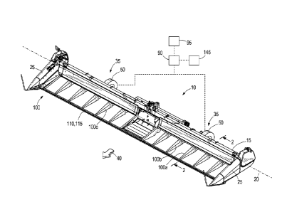
[0006] FIG. 1 is a perspective view of an agricultural harvesting head
unit.
[0007] FIG. 2 is a cross sectional view of the agricultural harvesting head
unit taken along
section line 2-2 of FIG. 1 illustrating a hydraulic locking assembly according
to one
embodiment of the disclosure with a frame of the agricultural harvesting head
unit engaging a
surface and a gauge assembly being spaced from the surface.
[0008] FIG. 3 is a cross sectional view of the agricultural harvesting head
unit taken along
section line 2-2 of FIG. 1 illustrating the hydraulic locking assembly with
the frame of the
agricultural harvesting head unit and the gauge assembly engaging the surface.
[0009] FIG. 4 is a cross sectional view of the agricultural harvesting head
unit taken along
section line 2-2 of FIG. 1 illustrating the hydraulic locking assembly with
the frame of the
2
Date Recue/Date Received 2020-04-23
agricultural harvesting head unit being spaced from the surface and the gauge
assembly engaging
the surface.
[0010] FIG. 5 is a top view of a portion of the agricultural harvesting
head unit of FIG. 1
illustrating the hydraulic locking assembly extending along a length of the
agricultural harvesting
head unit.
[0011] FIG. 6 is a cross sectional view of the agricultural harvesting head
unit taken along
section line 2-2 of FIG. 1 illustrating a mechanical locking assembly
according to another
embodiment of the disclosure with the frame of the agricultural harvesting
head unit engaging
the surface and the gauge assembly being spaced from the surface.
[0012] FIG. 7 is a cross sectional view of the agricultural harvesting head
unit taken along
section line 2-2 of FIG. 1 illustrating the mechanical locking assembly with
the frame of the
agricultural harvesting head unit and the gauge assembly engaging the surface.
[0013] FIG. 8 is a cross sectional view of the agricultural harvesting head
unit taken along
section line 2-2 of FIG. 1 illustrating the mechanical locking assembly with
the frame of the
agricultural harvesting head being spaced from the surface and the gauge
assembly engaging the
surface.
[0014] FIG. 9 is a top view of a portion of the agricultural harvesting
head unit of FIG. 1
illustrating the mechanical locking assembly extending along the length of the
agricultural
harvesting head.
DETAILED DESCRIPTION
[0015] Before any embodiments of the disclosure are explained in detail, it
is to be
understood that the disclosure is not limited in its application to the
details of construction and
the arrangement of components set forth in the following description or
illustrated in the
following drawings. The disclosure is capable of supporting other embodiments
and being
practiced or being carried out in various ways. Also, it is to be understood
that the phraseology
and teuninology used herein is for the purpose of description and should not
be regarded as
limiting. Temis of degree, such as "substantially," "about," "approximately,"
etc. are understood
3
Date Recue/Date Received 2020-04-23
by those of ordinary skill to refer to reasonable ranges outside of the given
value, for example,
general tolerances associated with manufacturing, assembly, and use of the
described
embodiments.
[0016] FIG. 1 illustrates a harvesting head unit 10 for an agricultural
combine harvester. The
head unit 10 unit includes a frame 15 having a longitudinal axis 20 extending
between side
housings 25 of the frame 15. The head unit 10 is moveable along a surface 30
that supports the
agricultural combine harvester.
[0017] The head unit 10 also includes gauge assemblies (e.g., gauge wheel
assemblies 35)
coupled to a rear side of the frame 15 in a travel direction 40 of the head
unit 10. In particular,
the gauge wheel assemblies 35 are pivotably coupled to the frame 15 about a
gauge member axis
45 (FIG. 2) to be selectively engageable with the surface 30. Each gauge wheel
assembly 35
includes a wheel 50 coupled to a support bracket 55, which is pivotably
coupled to the frame 15
about the gauge member axis 45. In other embodiments, the head unit 10 can
include one gauge
wheel assembly 35 or more than two gauge wheel assemblies 35.
[0018] With reference to FIG. 2, a control assembly 60 (e.g., a hydraulic
locking assembly)
includes a first hydraulic actuator 65 (e.g., a first hydraulic cylinder)
coupled to the frame 15 and
the support bracket 55.A first hydraulic line 70 is coupled to the first
hydraulic actuator 65 and
operable to introduce hydraulic fluid into the first hydraulic actuator 65 for
the gauge wheel
assembly 35 to move from a retracted position (FIG. 2) in which the wheel 50
is spaced from the
surface 30 into an extended position (FIGS. 3 and 4) in which the wheel 50 is
engaged with the
surface 30.A second hydraulic line 75 is also coupled to the first hydraulic
actuator 65 and is
operable to introduce hydraulic fluid into the first hydraulic actuator 65 for
the gauge wheel
assembly 35 to move from the extended position into the retracted position.
[0019] The control assembly 60 also includes a gauge sensor 80 coupled to
at least one
gauge wheel assembly 35 and is operable to measure an actual vertical position
85 of the frame
15 relative to the surface 30. In the illustrated embodiment, the gauge sensor
80 is in
communication with the first hydraulic actuator 65 to monitor movement of the
gauge wheel
assembly 35 between the extended and retracted positions, which correlates to
a position of the
frame 15 relative to the surface 30. For example, the gauge sensor 80 senses
when the gauge
4
Date Recue/Date Received 2020-04-23
wheel 50 is spaced from the surface 30, which correlates to the harvesting
head unit 10 being in a
lowered position with the frame 15/side housings 25 engaging the surface 30
(e.g., the vertical
position 85 is zero; FIG. 2). The gauge sensor 80 also senses when the gauge
wheel 50 engages
the surface 30 and senses a relative position of the gauge wheel 50/bracket 55
and the frame 15,
which correlates to the harvesting head unit 10 being in a raised position
with the frame 15
spaced from the surface 30 (e.g., the vertical position 85 is greater than
zero; FIG. 4). In other
embodiments, the sensor 85 can be coupled between the support bracket 55 and
the frame 15
adjacent the gauge member axis 45 to measure angular movement of the support
bracket 55
relative to the frame 15. The gauge sensor 80 is also in communication with a
control processor
90 (FIG. 1), and the control processor 90 is coupled to a control actuator 95.
The control actuator
95 is located within an operator cab of the agricultural combine harvester and
is operable to
control the gauge wheel assemblies 35 and the vertical position 85 of the head
unit 10 above the
surface 30, discussed in more detail below. In one embodiment, the control
actuator 95 can be a
rotatable dial, a user interface display, etc. in which the operator can
select a desired height of the
head unit 10 above the surface 30.
[0020] With reference back to FIG. 1, the head unit 10 also includes
support aims 100
pivotably coupled to the frame 15 about a support aim axis 105 (FIG. 2) and
are operable to
support a reciprocating knife 110 having cutting teeth 115. At least one of
the side housings 25
includes a drive mechanism (not shown) operable to reciprocate the knife 110
in directions along
the longitudinal axis 20 of the frame 15.
[0021] With reference to FIG. 2, the control assembly 60 also includes a
second hydraulic
actuator 120 (e.g., a second hydraulic cylinder) coupled to the frame 15 and a
first support aim
100a. The second hydraulic actuator 120 is fluidly coupled to the first
hydraulic actuator 65 by a
third hydraulic line 125 and is moveable between a depressurized state (FIGS.
2 and 3) and a
pressurized state (FIG. 4). When the second hydraulic actuator 120 is
depressurized, the first
support arm 100a is in an unlocked state and is freely pivotable relative to
the frame 15 about the
support arm axis 105. When the second hydraulic actuator 120 is pressurized,
the first support
aim 100a is in a locked state and is fixed relative to the frame 15. In
particular, the first support
aim 100a moves into engagement with a stop 130 of the frame 15 to fix the
first support aim
100a about the support aim axis 105 when the second hydraulic actuator 120 is
pressurized.
Date Recue/Date Received 2020-04-23
[0022] With reference to FIG. 5, the control assembly 60 also includes
third hydraulic
actuators 135 (e.g., third hydraulic cylinders) each coupled to one of the
remaining support aims
100b, 100c and the frame 15. Each third hydraulic actuator 135 is coupled to
its corresponding
support aim 100b, 100c and the frame 15 in a similar way the second hydraulic
actuator 120 is
coupled to the first support arm 100a and the frame 15. The third hydraulic
actuators 135 are in
communication with the second hydraulic actuator 120 by a fourth hydraulic
line 140 such that
the third hydraulic actuators 135 move concurrently with the second hydraulic
actuator 120. For
example, when the second hydraulic actuator 120 is depressurized, the third
hydraulic actuators
135 are also depressurized to allow the support arms 100b, 100c to pivot about
the support arm
axis 105. Moreover, when the second and third hydraulic actuators 120, 135 are
in the
depressurized state, the support arms 100a, 100b, 100c are independently
moveable relative to
each other. When the second hydraulic actuator 120 is pressurized, the third
hydraulic actuators
135 are also pressurized to fix the support arms 100b, 100c relative to the
frame 15.
[0023] The agricultural combine harvester is operable to move the head unit
10 between a
lowered position in which the frame 15 engages the surface 30 (e.g., the
vertical position 85 is
zero; FIGS. 2 and 3) and a raised position in which the frame 15 is spaced
from the surface 30
(e.g., the vertical position 85 is greater than zero; FIG. 4). In particular,
the agricultural combine
harvester includes a hydraulic system 145 (FIG. 1) in communication with the
control processor
90 to move the head unit 10 between the lowered and raised positions. In the
lowered position,
the side housings 25 engage the surface 30 to position the knife 110
relatively close to the
surface 30 (e.g., the cutting teeth 115 are positioned within about 3 inches
from the surface 30).
In other words, the side housings 25 at least partially support the head unit
10 above the surface
30 when in the lowered position. Moreover, the control processor 90 is able to
identify when the
head unit 10 is in the lowered position by a signal provided from the gauge
sensor 80. For
example, when the wheel 50 is spaced from the surface 30 (FIG. 2), the gauge
sensor 80
measures a first position of the first hydraulic actuator 65 representing the
wheel 50 being out of
engagement with the surface 30 and the head unit 10 being in the lowered
position. When the
wheel 50 and the side housings 25 are in engagement with the surface 30 (FIG.
3), the gauge
sensor 80 measures a second position of the first hydraulic actuator 65
representing the wheel 50
initially engaging the surface 30 but the head unit 10 still being in the
lowered position as the
side housings 25 are also in engagement with the surface 30. The first
hydraulic actuator 65
6
Date Recue/Date Received 2020-04-23
moves from the first position (FIG. 2) to the second position (FIG. 3) in
response to an operator
of the combine harvester actuating the control actuator 95 thereby having
hydraulic fluid pumped
into the first hydraulic actuator 65 via the first hydraulic line 70. In some
embodiments, the first
hydraulic actuator 65 can be maintained in the first position (FIG. 2) by
hydraulic fluid entering
the first hydraulic actuator 65 via the second hydraulic line 75. In further
embodiments, the first
hydraulic actuator 65 can be biased toward the first position (FIG. 2) by a
biasing member (e.g.,
a spring) to maintain the gauge wheel 50 out of engagement with the surface
30. In yet further
embodiments, the first hydraulic actuator 65 can be freely moveable (e.g.,
depressurized) such
that the wheel 50 engages the surface 30 and is freely pivotable about the
gauge wheel axis 45 as
the head unit 10 is in the lowered position. Furthermore, the second and third
hydraulic actuators
120, 135 are depressurized when the head unit 10 is in the lowered position.
[0024] As the head unit 10 moves along the surface 30, the independent
movement of the
support aims 100a, 100b, 100c allow the knife 110 to bend along the
longitudinal axis 20 of the
frame 15 while the knife 110 reciprocates along the longitudinal axis 20. For
example, portions
of the knife 110 are allowed to flex as each support arm 100 moves over uneven
contours of the
surface 30. This allows for the cutting teeth 115 to remain relatively close
to the uneven surface
30 without digging in or engaging the surface 30. As such, plant matter (e.g.,
crops such as corn
stalks, bean stalks, etc.) extending above the surface 30 can be cut
relatively close to the surface
30 by the knife 110 while the head unit 10 is in the lowered position.
[0025] In some situations, it is desirable to lock the knife 110 from
bending and position the
head unit 10 in the raised position. To do this, the operator of the
agricultural combine harvester
selects a desired height of the head unit 10 above the surface 30 via the
control actuator 95, and
the control processor 90 determines the actual height of the head unit 10
above the surface by the
gauge sensor 80 such that the control processor 90 can control the hydraulic
system 145 to raise
the head unit 10 to the desired height. In addition, the control assembly 60
locks the support aims
100 in the locked state to inhibit bending of the knife 110.
[0026] In particular, hydraulic fluid is pumped into the first hydraulic
actuator 65 upon
selecting the desired height of the head unit 10 via the control actuator 95.
As such, the first
hydraulic actuator 65 is pressurized to push the gauge wheel 50 toward the
surface 30, and the
7
Date Recue/Date Received 2020-04-23
second and third hydraulic actuators 120, 135 are also pressurized via the
hydraulic lines 125,
140 to move the support aims 100 into the locked position. As such, the
control assembly 60
provides simultaneous movement of the gauge wheel assemblies 35 and support
aims 100 as the
hydraulic system 145 raises the head unit 10 to the desired height. In other
embodiments, the
control assembly 60 can separately move the gauge wheel assemblies 35 and the
support aims
100. For example, the support aims 100 can be moved into the locked state
before the head unit
moves into the raised position. In some embodiments, the first hydraulic
actuator 65 can assist
the hydraulic system 145 raise the head unit 10 above the surface 30 such that
the gauge wheel
assemblies 35 can at least partially support the weight of the frame 15.
[0027] Once the support aims 100 are in the locked state, the knife 110 is
inhibited from
bending along the longitudinal axis 20 of the frame 15. This enables the
cutting teeth 115 to
simply reciprocate along the longitudinal axis 20 of the frame 15 to shear
plant matter at a
desired height above the surface 30.
[0028] To move the head unit 10 back into the lowered position (FIG. 3),
the control actuator
95 is actuated for the hydraulic system 145 to lower the frame 15. Pressure
within the first
hydraulic actuator 65 is also reduced allowing the gauge assemblies 35 to move
relative to the
frame 15 as the head unit 10 is being lowered. Once the frame 15 engages the
surface 30,
pressure within the second and third hydraulic actuators 120, 135 are also
reduced for the support
aims 100 to return to the unlocked state. As described above, the gauge wheel
assemblies 35 can
remain engaged with the surface 30 but are freely pivotable (FIG. 3) or the
gauge wheel
assemblies 35 can be moved out of engagement with the surface 30 (FIG. 2) when
the support
aims 100 move into the unlocked state.
[0029] In sum, the control assembly 60 moves the support aims 100 into the
locked position
(FIG. 4) based on the vertical position 85 of the head unit 10 being non-zero
with the vertical
position 85 being measured by the gauge assembly 35. The gauge assembly 35 is
within a
certain range of positions relative to the frame 15 when the head unit 10 is
in a raised position.
The control assembly 60 also allows the support aims 100 to move into the
unlocked position
(FIGS. 2 and 3) based on the vertical position 85 of the head unit 10 being
zero. The gauge
8
Date Recue/Date Received 2020-04-23
assembly 35 is within a different range of positions relative to the frame 15
when the head unit
is in the lowered position.
[0030] In further embodiments, at least one gauge wheel assembly 35 can be
replaced with a
rigid probe pivotably coupled to the frame 15 about the gauge member axis 45
and biased into
engagement with the surface 30 by, for example, a torsion spring. The gauge
sensor 80 is coupled
to the probe to measure an angular position of the probe relative to the frame
15 about the gauge
member axis 45 to determine a position of the head unit 10 relative to the
surface 30.
Accordingly, the probe is in a first range of angular positions relative to
the frame 15 when the
head unit 10 is in the lowered position (FIGS. 2 and 3), and the probe is
within a second range of
angular positions relative to the frame 15 when the head unit 10 is in the
raised position (FIG. 4).
In yet further embodiments, at least one gauge wheel assembly 35 can be
replaced with an optic
sensor to measure a height of the frame 15 relative to the surface 30.
[0031] FIGS. 6-9 illustrate a control assembly 260 (e.g., a mechanical
locking assembly)
according to another embodiment. The control assembly 260 is similar to the
control assembly
60; therefore, similar components are designated with similar references
numbers each
incremented by 200. At least some differences and/or at least some
similarities between the
control assemblies 60, 260 will be discussed in detail below. In addition,
components or features
described with respect to only one or some of the embodiments described herein
are equally
applicable to any other embodiments described herein.
[0032] The control assembly 260 omits the second and third hydraulic
actuators 120, 135,
and includes a linkage assembly 355 (FIG. 6) coupled between at least one
gauge wheel
assembly 35 and the support aims 100. However, the linkage assembly 355
functions similar to
the second and third hydraulic actuators 120, 35 in that the linkage assembly
355 moves the
support aims 100 into the locked state. The linkage assembly 355 includes a
first linkage member
360 having a biasing member 365 and a first portion 370 with the first portion
370 being
pivotably coupled to the support bracket 55 of the gauge wheel assembly 35. A
first mechanical
actuator 320 (e.g., a bell crank) of the linkage assembly 355 is coupled to a
second portion 380
of the first linkage member 360. The first mechanical actuator 320 is
pivotably coupled to the
9
Date Recue/Date Received 2020-04-23
frame 15 about an actuator axis 385 and includes a surface 390 engageable with
the first support
aim 100a.
[0033] With reference to FIG. 9, the linkage assembly 355 also includes
second mechanical
actuators 335 pivotably coupled to the frame 15 about the actuator axis 385
with each second
mechanical actuator 335 associated with one support arm 100b, 100c. A
mechanical coupler 340
is coupled to the first and second mechanical actuators 320, 335 to provide
concurrent movement
of the first and second mechanical actuators 320, 335.
[0034] With reference back to FIG. 6, the head unit 10 is in the lowered
position with the
frame 15 engaging the surface 30 and the gauge wheel assembly 35 spaced from
the surface 30.
In the lowered position, the linkage assembly 355 is arranged such that the
first and second
mechanical actuators 320, 335 allow the support arms 100 to independently
pivot. In one
embodiment, the biasing member 365 biases the gauge wheel 35 out of engagement
with the
surface 30 when the head unit 10 is in the lowered position.
[0035] With actuation of the control actuator 95 to move the head unit 10
into a raised
position, the first hydraulic actuator 65 is pressurized to move the gauge
wheel 50 into
engagement with the surface 30 (FIG. 7). The first linkage member 360 includes
the biasing
member 365 to allow for relative movement of the first and second portions
370, 380 so that the
first and second mechanical actuators 320, 335 do not move the support arms
100 into the locked
state before the gauge wheel 50 engages the surface 30. Once the gauge wheel
50 engages the
surface 30 (FIG. 7), the first linkage member 360 can then move the first and
second mechanical
actuators 320, 335 about the actuator axis 385 to move the support arms 100
into the locked state
(FIG. 8)as the hydraulic system 145 raises the head unit 10 from the lowered
position. In other
words, the control assembly 260 moves the support arms 100 into the locked
position based on
the vertical position 85 of the head unit 10.
[0036] To lower the head unit 10 back into engagement with the surface 30,
the hydraulic
system 145 lowers the head unit 10 and pressure within the first hydraulic
actuator 65 is released
allowing movement of the gauge wheel assemblies 35 relative to the frame 15.
Once the frame
15 engages the surface 30 again, the first linkage member 360 allows the first
and second
Date Recue/Date Received 2020-04-23
mechanical actuators 320, 335 to pivot about the actuator axis 385 for the
support arms 100 to
return to the unlocked state.
[0037] In other embodiments, the control assembly 260 can also include the
second and third
hydraulic actuators 120, 135 for the support arms 100 to be independently
controlled relative to
the first linkage member 360.
[0038] Although the disclosure has been described in detail with reference
to certain
preferred embodiments, variations and modifications exist within the scope and
spirit of one or
more independent aspects of the disclosure as described. Various features and
advantages of the
disclosure are set forth in the following claims.
11
Date Recue/Date Received 2020-04-23