Note: Descriptions are shown in the official language in which they were submitted.
CA 03079606 2020-04-16
WO 2019/075566
PCT/CA2018/051311
1
FUEL PUMP MANAGEMENT SYSTEM AND METHOD OF OPERATING A FUEL
PUMP MANAGEMENT SYSTEM
CROSS-REFERENCE TO RELATED APPLICATIONS
[01] The present application claims priority to U.S. Provisional Patent
Application No.
62/574,385, filed October 19, 2017, the entirety of which is incorporated
herein by reference.
FIELD
[02] The present technology relates to fuel pump management systems and
methods for
operating fuel pump management systems. In particular, the systems and methods
allow
analysing a level of fuel fluid to determine whether a fuel pump is to be shut
down.
BACKGROUND
[03] Operating aircraft at low fuel states may present risks of fuel tank
ignitions. Without
safeguard mechanisms, a fuel pump may keep operating even though a fuel tank
to which it is
fluidly connected is empty or close to be empty. Such situations may result in
the fuel pump
.. heating up thereby presenting a risk of failures and/or a risk of ignitions
which, in turn, may
result in a fire hazard at the aircraft level. As an example, such situations
may occur when an
aircraft is on the ground and maintenance personnel forget to turn the fuel
pump off
[04] In order to mitigate risks associated with fuel pump overheating,
multiple approaches
have been investigated. Such approaches comprise imbedding one or more thermal
switches
and/or one or more thermal fuses in a stator wiring of the fuel pump. The
thermal switch
and/or the thermal fuse typically trigger upon being heated above a certain
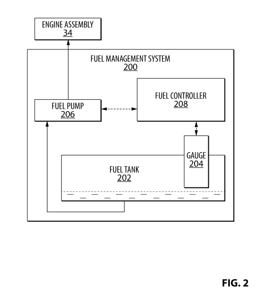
level. This
approach may result, if detection of the triggering of the overheating has
occurred, in a need
to replace thermal switch and/or the thermal fuse or, if detection of the
triggering of the
overheating has not occurred, in a dormant failure of the thermal switch
and/or the thermal
fuse. As a result of these potential dormant failures, additional protections
may be needed.
Such additional protections may comprise imbedding a ground fault interrupter
(GFI) or a
fast acting arc fault interrupter (FAAF) in a circuitry of the fuel pump. Such
additional
protections may present shortcomings as a GFI does not (1) detect dry running
of the fuel
tank (i.e., it only protects against ignition from wire arcing when the fuel
tank is empty) and
CA 03079606 2020-04-16
WO 2019/075566
PCT/CA2018/051311
2
(2) protect against foreign object damage (FOD) which may itself be an
ignition source if
lodged in an impeller during a dry running situation. Furthermore, additional
wiring and/or
testing may also be needed to demonstrate that the GFI and/of the FAAF are
operational.
[05] Alternatively, additional protections may also comprise imbedding dual
fuses for each
wire in the stator wiring of the fuel pump. Those approaches may however
present
shortcomings, amongst which, but without being limitative, adding components
to the fuel
system of the aircraft thereby adding complexity and/or weight.
[06] A first alternative approach comprises the system and method described in
U.S. Patent
6,908,289 to Hydro-Aire, Inc. The system and method monitor fuel pressure
within the fuel
tank to shut-off the system if the pressure drops below a threshold value. The
system and
method attempt to automate shutting down of the fuel based on the fuel pump
pressure levels.
[07] A second alternative approach comprises the system and method described
in U.S.
Patent 7,352,550 to TDG Aerospace, Inc. The system and method relate to a
fault detection
circuitry triggering a shutdown of a fuel pump.
[08] Even though multiple approaches have been developed, improvements may
nonetheless still be desirable.
[09] The subject matter discussed in the background section should not be
assumed to be
prior art merely as a result of its mention in the background section.
Similarly, a problem
mentioned in the background section or associated with the subject matter of
the background
section should not be assumed to have been previously recognized in the prior
art. The
subject matter in the background section merely represents different
approaches.
SUMMARY
[ 1 0] In one aspect, various implementations of the present technology
provide a fuel pump
management system for an aircraft, the system comprising:
a fuel gauge configured to electronically read a level of fuel fluid contained
in a fuel
tank;
a fuel pump in fluid communication with the fuel tank and a power unit to be
alimented in fuel fluid; and
CA 03079606 2020-04-16
WO 2019/075566
PCT/CA2018/051311
3
a controller connected to the fuel gauge and the fuel pump, the controller
being
configured to (1) analyse the level of fuel fluid read by the fuel gauge and
(2) upon
determining that the level of fuel fluid is equal or below a predetermined
fuel level
threshold, cause the fuel pump to be shut down.
[11] In another aspect, the fuel gauge is located within the fuel tank.
[12] In yet another aspect, the fuel gauge comprises at least one of a
capacitance probe and
a proximity sensing unit.
[13] In another aspect, the fuel gauge comprises at least one of an ultrasonic
transducer, a
magnetoresistive level transmitter, a laser transmitter and a guided wave
radar.
[14] In yet another aspect, the fuel gauge is configured to transmit one or
more readings of
the level of fuel fluid contained in the fuel tank to the fuel controller.
[15] In another aspect, the predetermined fuel level threshold is a minimum
threshold
determined so that the fuel pump is not subjected to one of a drop of fuel
pressure and foreign
object ignition before being shut down.
[16] In yet another aspect, shutting down the fuel pump comprises switching
off current
flowing to the fuel pump.
[17] In another aspect, the fuel pump comprises a solenoid and wherein
shutting down the
fuel pump comprises sending a signal to the solenoid so that the solenoid
causes switching
off current flowing to the fuel pump.
[18] In yet another aspect, prior to causing the fuel pump to be shut down,
the controller
determines whether an aircraft in which the fuel pump management system is
installed is on
the ground.
[19] In another aspect, the power unit is one of an aircraft engine and an
auxiliary power
unit (APU).
.. [20] In another aspect, various implementations of the present technology
provide a
method of operating a fuel pump management system of an aircraft, the method
comprising:
CA 03079606 2020-04-16
WO 2019/075566
PCT/CA2018/051311
4
receiving, from a fuel gauge, an electronic reading of a level of fuel fluid
contained in
a fuel tank; and
analysing the electronic reading of the level of the fuel fluid, the analysing
comprising:
upon determining that the level of fuel fluid is equal or below a
predetermined fuel
level threshold, causing a fuel pump in communication with the fuel tank to be
shut down.
[21] In another aspect, the fuel gauge is located within the fuel tank.
[22] In yet another aspect, the fuel gauge comprises at least one of a
capacitance probe and
a proximity sensing unit.
[23] In another aspect, the fuel gauge comprises one of an ultrasonic
transducer, a
magnetoresistive level transmitter, a laser transmitter and a guided wave
radar.
[24] In yet another aspect, the fuel gauge is configured to transmit one or
more readings of
the level of fuel fluid contained in the fuel tank to the fuel controller.
[25] In another aspect, the predetermined fuel level threshold is a minimum
threshold
determined so that the fuel pump is not subjected to one of a drop of fuel
pressure and foreign
object ignition before being shut down.
[26] In yet another aspect, shutting down the fuel pump comprises switching
off current
flowing to the fuel pump.
[27] In another aspect, the fuel pump comprises a solenoid and wherein
shutting down the
fuel pump comprises sending a signal to the solenoid so that the solenoid
causes switching
off current flowing to the fuel pump.
[28] In yet another aspect, prior to causing the fuel pump to be shut down,
the controller
determines whether an aircraft in which the fuel pump management system is
installed is on
the ground.
[29] In another aspect, various implementations of the present technology
provide a
controller comprising a processor and a non-transitory computer-readable
medium, the non-
CA 03079606 2020-04-16
WO 2019/075566
PCT/CA2018/051311
transitory computer-readable medium comprising control logic which, upon
execution by the
processor, causes operating a fuel pump management system of an aircraft.
[30] In other aspects, various implementations of the present technology
provide a non-
transitory computer-readable medium storing program instructions for operating
a fuel pump
5 management system of an aircraft, the program instructions being
executable by a processor
of a computer-based system to carry out one or more of the above-recited
methods.
[31] In other aspects, various implementations of the present technology
provide a
computer-based system, such as, for example, but without being limitative, an
electrical
system controller comprising at least one processor and a memory storing
program
instructions for operating a fuel pump management system of an aircraft, the
program
instructions being executable by the at least one processor of the electrical
system controller
to carry out one or more of the above-recited methods.
[32] In the context of the present specification, unless expressly provided
otherwise, a
computer system may refer, but is not limited to, an "electronic device", a
"controller", a
"fuel controller", a "control computer", a "control system", a "computer-based
system", a
"fuel management system" and/or any combination thereof appropriate to the
relevant task at
hand.
[33] In the context of the present specification, unless expressly provided
otherwise, the
expression "computer-readable medium" and "memory" are intended to include
media of any
nature and kind whatsoever, non-limiting examples of which include RAM, ROM,
disks
(CD-ROMs, DVDs, floppy disks, hard disk drives, etc.), USB keys, flash memory
cards,
solid state-drives, and tape drives. Still in the context of the present
specification, "a"
computer-readable medium and "the" computer-readable medium should not be
construed as
being the same computer-readable medium. To the contrary, and whenever
appropriate, "a"
computer-readable medium and "the" computer-readable medium may also be
construed as a
first computer-readable medium and a second computer-readable medium.
[34] In the context of the present specification, unless expressly provided
otherwise, the
words "first", "second", "third", etc. have been used as adjectives only for
the purpose of
allowing for distinction between the nouns that they modify from one another,
and not for the
purpose of describing any particular relationship between those nouns.
CA 03079606 2020-04-16
WO 2019/075566
PCT/CA2018/051311
6
[35] Implementations of the present technology each have at least one of the
above-
mentioned object and/or aspects, but do not necessarily have all of them. It
should be
understood that some aspects of the present technology that have resulted from
attempting to
attain the above-mentioned object may not satisfy this object and/or may
satisfy other objects
.. not specifically recited herein.
[36] Additional and/or alternative features, aspects and advantages of
implementations of
the present technology will become apparent from the following description,
the
accompanying drawings and the appended claims.
BRIEF DESCRIPTION OF THE DRAWINGS
[37] For a better understanding of the present technology, as well as other
aspects and
further features thereof, reference is made to the following description which
is to be used in
conjunction with the accompanying drawings, where:
[38] Figure 1 is a perspective view taken from a top, front, left side of an
aircraft;
[39] Figure 2 is a diagram of a fuel management system in accordance with an
embodiment of the present technology;
[40] Figure 3 is a diagram of a computing environment in accordance with an
embodiment
of the present technology; and
[41] Figure 4 is a diagram illustrating a flowchart illustrating a computer-
implemented
method implementing embodiments of the present technology.
[42] It should also be noted that, unless otherwise explicitly specified
herein, the drawings
are not to scale.
DETAILED DESCRIPTION
[43] The examples and conditional language recited herein are principally
intended to aid
the reader in understanding the principles of the present technology and not
to limit its scope
to such specifically recited examples and conditions. It will be appreciated
that those skilled
in the art may devise various arrangements which, although not explicitly
described or shown
herein, nonetheless embody the principles of the present technology and are
included within
its spirit and scope.
CA 03079606 2020-04-16
WO 2019/075566
PCT/CA2018/051311
7
[44] Furthermore, as an aid to understanding, the following description may
describe
relatively simplified implementations of the present technology. As persons
skilled in the art
would understand, various implementations of the present technology may be of
a greater
complexity.
[45] In some cases, what are believed to be helpful examples of modifications
to the
present technology may also be set forth. This is done merely as an aid to
understanding, and,
again, not to define the scope or set forth the bounds of the present
technology. These
modifications are not an exhaustive list, and a person skilled in the art may
make other
modifications while nonetheless remaining within the scope of the present
technology.
Further, where no examples of modifications have been set forth, it should not
be interpreted
that no modifications are possible and/or that what is described is the sole
manner of
implementing that element of the present technology.
[46] Moreover, all statements herein reciting principles, aspects, and
implementations of
the present technology, as well as specific examples thereof, are intended to
encompass both
structural and functional equivalents thereof, whether they are currently
known or developed
in the future. Thus, for example, it will be appreciated by those skilled in
the art that any
block diagrams herein represent conceptual views of illustrative circuitry
embodying the
principles of the present technology. Similarly, it will be appreciated that
any flowcharts,
flow diagrams, state transition diagrams, pseudo-code, and the like represent
various
processes which may be substantially represented in computer-readable media
and so
executed by a computer or processor, whether or not such computer or processor
is explicitly
shown.
[47] The functions of the various elements shown in the figures, including any
functional
block labeled as a "processor" or a "controller", may be provided through the
use of
dedicated hardware as well as hardware capable of executing software in
association with
appropriate software. When provided by a processor, the functions may be
provided by a
single dedicated processor, by a single shared processor, or by a plurality of
individual
processors, some of which may be shared. In some embodiments of the present
technology,
the processor may be a general purpose processor, such as a central processing
unit (CPU) or
a processor dedicated to a specific purpose, such as a digital signal
processor (DSP).
Moreover, explicit use of the term "processor" or "controller" should not be
construed to refer
exclusively to hardware capable of executing software, and may implicitly
include, without
CA 03079606 2020-04-16
WO 2019/075566
PCT/CA2018/051311
8
limitation, application specific integrated circuit (ASIC), field programmable
gate array
(FPGA), read-only memory (ROM) for storing software, random access memory
(RAM), and
non-volatile storage. Other hardware, conventional and/or custom, may also be
included.
[48] Software modules, or simply modules which are implied to be software, may
be
represented herein as any combination of flowchart elements or other elements
indicating
performance of process steps and/or textual description. Such modules may be
executed by
hardware that is expressly or implicitly shown.
[49] With these fundamentals in place, we will now consider some non-limiting
examples
to illustrate various implementations of aspects of the present technology.
[50] Referring to FIG. 1, there is shown an aircraft 10. The aircraft 10 is an
exemplary
implementation of an aircraft and other types of aircraft are contemplated.
The aircraft 10 has
a fuselage 12, a cockpit 14 at a front of the fuselage 12 and a tail 16 at a
rear of the fuselage
12. The tail 16 has left and right horizontal stabilizers 18 and a vertical
stabilizer 20. Each
horizontal stabilizer 18 is provided with an elevator 22 used to control the
pitch of the aircraft
10. The vertical stabilizer 20 is provided with a rudder 24 used to control
the yaw of the
aircraft 10. The aircraft 10 also has a pair of wings 26. The left wing 26 is
connected to the
fuselage 12 and extends on a left side thereof The right wing 26 is connected
to the fuselage
12 and extends on a right side thereof The wings 26 are provided with flaps 28
and ailerons
30. The flaps 28 are used to control the lift of the aircraft 10 and the
ailerons 30 are used to
control the roll of the aircraft 10. Optionally, each wing 26 is provided with
a winglet 32 at a
tip thereof Left and right engine assemblies 34 are connected to a bottom of
the left and
right wings 26 respectively, as will be described in greater detail below. It
is contemplated
that more than one engine assembly 34 could be connected to each wing 26. The
aircraft 10
is provided with many more components and systems, such as a landing gear and
auxiliary
power unit, which will not be described herein.
[51]
Referring now concurrently to FIG. 1 and 2, the left engine assembly 34 and a
fuel
management system 200 will be described in more detail. As the right engine
assembly 34 is
similar to the left engine assembly 34, it will not be described in detail
herein. Elements of
the right engine assembly 34 that correspond to those of the left engine
assembly 34 have
been labeled with the same reference in the figures.
CA 03079606 2020-04-16
WO 2019/075566
PCT/CA2018/051311
9
[52] The
left engine assembly 34 has a nacelle 50 inside which is an engine 52. In the
present implementation, the engine 52 is a turbofan engine such as the Pratt &
WhitneyTM
PW1SOOGTM turbofan engine. It is contemplated that other turbofan engines
could be used.
It is also contemplated that an engine other than a turbofan engine could be
used.
[53] A pylon 54 is connected between the nacelle 50 and a bottom of the
left wing 26,
thereby connecting the engine 52 to the left wing 26. The pylon 54 extends
along a top of the
nacelle 50. A majority of the pylon 54 extends forward of a leading edge 56 of
the left wing
26. The top, rear portion of the pylon 54 connects to the bottom, front
portion of the wing 26.
[54] As can be seen in FIG. 2, the engine assembly 34 is also fluidly
connected to the
fuel management system 200. In some embodiments, the fuel management system
200 may
equally be referred to as an aircraft fuel system. Broadly speaking the fuel
management
system 200 may rely on systems and control logic to pump, manage and deliver
fuel fluid
(equally referred to as jet fuel) so as to ensure that the engine assembly 34
receives a proper
amount of fuel fluid at any stage of operations of the aircraft. Such stage of
operations may
comprise operations while the aircraft is stationary on the ground, taxiing
and/or in-flight
(e.g., during take-off, cruise and/or landing). In some embodiments, the fuel
management
system 200 may comprise additional functionalities, such as, but without being
limitative,
management of a center of gravity of the aircraft by dynamically adjusting
allocation of fuel
fluid in each one of the fuel tanks. The fuel management system 200 may also
comprise other
functionalities which may become apparent to the person skilled in the art of
the present
technology.
[55] In the illustrated embodiment, the fuel management system 200
comprises a fuel
tank 202, one or more fuel gauges 204, one or more fuel pumps 206 and one or
more fuel
controllers 208. Additional systems and components may also be part of the
fuel management
system 200 such as fuel pipes and fuel valves. Such additional systems and
components may
become readily apparent to the person skilled in the art of the present
technology.
[56] The number of fuel tanks, fuel gauges and fuel pumps may vary
depending on the
configuration of the aircraft. In some embodiments, each fuel tank is
associated with a
corresponding fuel pump and a corresponding fuel gauge. In some alternative
embodiments,
each fuel tank may be associated with a plurality of fuel pumps and/or fuel
gauges. In some
embodiments, a plurality of fuel tanks may be distributed across the aircraft,
such as, but
CA 03079606 2020-04-16
WO 2019/075566
PCT/CA2018/051311
without being limitative, in the wings and/or in the fuselage (e.g., within
the belly fairing). In
some alternative embodiments, such as in fighter jets, the fuel tanks may be
located
externally (e.g., drop tanks attached to a wing).
[57] In some embodiments, the fuel tank 202 is "built-in" a structure of
the aircraft that
5 is sealed to allow fuel storage. As previously mentioned, the fuel tank
202 may be located at
various portions of the aircraft, such as, but without being limitative, in
the wings, in the
fuselage and/or empennage of the aircraft.
[58] In some embodiments, the fuel gauge 204 is installed with respect to
the fuel tank
202 so as to read a level of fuel fluid contained in the fuel tank 202. In
some embodiments,
10 the fuel gauge 204 may equally be referred to as a sensor and/or a probe.
In some
embodiments, the fuel gauge 204 is located within the fuel tank 202. In some
embodiments,
the fuel gauge 204 is integrally formed with the fuel tank 202. In some
embodiments, the fuel
gauge 204 is configured so as to allow a direct reading of the level of the
fuel fluid. In some
embodiments, the reading of the level is done directly and electronically
thereby allowing to
accurately determine a level of the fuel level. In some embodiments, the
electronic reading
allows a degree of accuracy that would have other not be possible with
conventional gauges,
such as mechanical probes.
[59] In some embodiments, the fuel gauge 204 may comprise a capacitance
probe
and/or proximity sensing unit. In some embodiments, the fuel gauge 204 may
comprise an
ultrasonic transducer, a magnetoresistive level transmitter, a laser
transmitter and/or a guided
wave radar.
[60] In some embodiments, the fuel gauge 204 may comprise various types of
fuel-
immersed gauges, sensors and/or probes. In some embodiments, the fuel gauge
204 may
comprise one or more probes that consist of two concentric metallic cylinders
that are
mounted vertically onto a structure of the fuel tank 202. The probes measure a
fuel height at
the probe locations. When no fuel is present, the probes may record dry
capacitance of
surrounding air. The dry capacitance may be different from probe to probe as
it depends on
the height of the probes. Probe heights may differ within the fuel tank
because of the
structural design of the fuel tank 202 (e.g., wing tank, fuselage tank). When
fuel is introduced
into the fuel tank 202, a space between the concentric cylinders fills up with
fuel fluid
thereby changing the capacitance measured by the probes. The change in
capacitance may be
CA 03079606 2020-04-16
WO 2019/075566
PCT/CA2018/051311
11
recorded by the probes and may be proportional to a fuel height. Various
methods may then
be relied upon to calculate a volume from this measurement. One such method
comprises
recording the fuel height and calculate a volume of fuel fluid based on
modeling a plane of
fuel fluid using at least three points (i.e., at least three probes within the
fuel tank 202). The
volume of fuel fluid may then be relied upon to determine a quantity of fuel
fluid inside the
fuel tank 202. In some embodiments, a fuel density may also be determined by
inputting a
constant value within the control software and/or measuring the fuel density
inside the fuel
tank 202. In some embodiments, the fuel density may be measured by using
permittivity
and/or by using a densitometer. The fuel density may be relied upon to convert
the fuel
volume to fuel mass.
[61] In some embodiments, when the fuel level reaches a low level, a single
probe
located at low point of the fuel tank 202 may be relied upon to trigger low
fuel quantity. If
fuel fluid level is below a threshold, then determination may be made that one
or more fuel
pumps is to be shut down. In some embodiments, low fuel level sensing may be
implemented
via electrical float switches and/or thermistor type sensors.
[62] In some embodiments, the fuel gauge 204 allows electronical reading of
the level
at a given frequency. In some embodiments, the electronical reading is
continuous and in real
time. In such embodiments, the fuel gauge 204 may continuously transmit
readings of the
level of fuel fluid to the fuel controller 208.
[63] In some embodiments, the fuel pump 206 may be an electric pump fluidly
connected to the fuel tank 202 so as to pump fuel fluid from the fuel tank 202
to the engine
assembly 34. In some embodiments, the fuel pump 206 may equally pump fuel
fluid from the
fuel tank 202 to the APU without departing from the scope of the present
technology. In
some embodiments, the fuel pump 206 may be electrically controlled through a
solenoid
electrically connected to the fuel controller 208. Further details as to how
the fuel pump 206
may be implemented will become apparent to the person skilled in the art of
the present
technology.
[64] In
some embodiments, the fuel controller 208 may be connected to the fuel gauge
204 and/or the fuel pump 206 either via wires or wirelessly. In some
embodiments, the fuel
controller 208 is part of the avionics of the aircraft. In some alternative
embodiments, the fuel
controller 208 may be an independent component or may be part of a system
operating
CA 03079606 2020-04-16
WO 2019/075566
PCT/CA2018/051311
12
control logic so as to implement a fuel controller 208. Further details as to
how the fuel
controller 208 may be implemented is further described in connection with the
description of
FIG. 3.
[65] In
some embodiments, the fuel controller 208 executes control logic so as to
receive readings from one or more fuel gauge 204 and analyse the readings. In
some
embodiments, the analysis further comprises comparing the level of fuel fluid
(read by the
one or more fuel gauge 204) with a threshold. In some embodiments, the
threshold may be a
predetermined value. In some embodiments, the predetermined value is
associated with a
volume unit (e.g., liter).
[66] In some
embodiments, the predetermined value may be edited by a user (e.g., a
pilot, a co-pilot, maintenance personnel). In some embodiments, the
predetermined value
may be automatically calculated and/or dynamically adjusted by the fuel
controller 208
and/or one or more systems of the avionics. The predetermined threshold is a
minimum
threshold determined so that the fuel pump is not subjected to a drop of fuel
pressure and/or
foreign object ignition before being shut down. In some embodiments, each one
of the one or
more fuel pumps 206 and/or each one of the one or more fuel tanks 202 may be
associated
with a corresponding predetermined threshold and/or a corresponding fuel
controller 208. As
an example, a first fuel tank may be associated with two fuel pumps and one
fuel controller.
In such an example, a single threshold may be relied upon by the fuel
controller to determine
whether the two fuel pumps have to be shut down. In other embodiments,
distinct threshold
may be relied upon for each one of the two fuel pumps. In other embodiments,
the fuel
controller may be associated with multiple fuel pumps installed in distinct
fuel tanks.
Multiple variations may therefore be envisioned without departing from the
scope of the
present technology.
[67] In some
embodiments, upon determining that the level of fuel fluid is equal or
below the threshold, the fuel controller 208 causes the one or more fuel pumps
206 to shut
down. In some embodiments, causing the one or more fuel pumps 206 to shut down
comprises issuing a signal to an electric control system of the aircraft to
shut down the one or
more fuel pumps 206. In some embodiments, causing the one or more fuel pumps
206 to shut
down comprises switching off current flowing to the fuel pump. In some
embodiments, the
one or more fuel pumps 206 comprise a solenoid and causing the one or more
fuel pumps 206
to shut down comprises sending a signal to the solenoid so that the solenoid
causes switching
CA 03079606 2020-04-16
WO 2019/075566
PCT/CA2018/051311
13
off current flowing to the one or more fuel pumps 206. In some embodiments,
the fuel
controller 208 is electrically connected to the one or more fuel pumps 206
directly or
indirectly (e.g., via a relay in an electrical junction box).
[68] In some embodiments, the fuel controller 208 determines whether the
aircraft is on
the ground or in-flight. In some embodiments, the fuel controller 208 not only
determines
whether the aircraft is on the ground but also whether the aircraft is taxiing
or not. In some
embodiments, determining whether the aircraft is on the ground or in-flight is
based on
readings obtained from the one or more landing gears of the aircraft (e.g.,
weight on wheels
determination). In some embodiments, the fuel controller 208 causes the one or
more fuel
pumps 206 to shut down only if it has previously determined that the aircraft
is on the
ground. Such embodiments allow providing hazard protection during maintenance
operations
while ensuring that the one or more fuel pumps 206 remain operational during
taxiing and/or
in-flight even though the level of fuel fluid is equal or below the threshold.
[69] Amongst multiple benefits, the fuel management system 200 described in
the
paragraphs above may allow (1) increasing reliability by limiting tripping of
the thermal
switches and/or one or the thermal fuses of the fuel pumps; (2) avoiding a
necessity to
include one or more GFIs in the fuel pumps; (3) reducing chances of
inadvertent dry running
of the fuel pumps; and/or (4) automatically shutting down one or more fuel
pumps before the
one or more fuel pump be subjected to a drop of fuel pressure and/or foreign
object ignition
before being shut down.
[70] Turning now to FIG. 3, a diagram of a computing environment 300 in
accordance
with an embodiment of the present technology is shown. In some embodiments,
the
computing environment 300 may be implemented by the fuel controller 208. In
some
embodiments, the computing environment 300 comprises various hardware
components
including one or more single or multi-core processors collectively represented
by a processor
310, a solid-state drive 320, a random access memory 330 and an input/output
interface 350.
The computing environment 300 may be a computer specifically designed for
installation into
an aircraft. In some alternative embodiments, the computing environment 300
may be a
generic computer system adapted to meet certain requirements, such as, but not
limited to,
certification requirements. The computing environment 300 may be an
"electronic device", a
"controller", a "control computer", a "control system", a "computer-based
system", a "fuel
controller", a "fuel management system" and/or any combination thereof
appropriate to the
CA 03079606 2020-04-16
WO 2019/075566
PCT/CA2018/051311
14
relevant task at hand. In some embodiments, the computing environment 300 may
also be a
sub-system of one of the above-listed systems. In some other embodiments, the
computing
environment 300 may be an "off the shelf' generic computer system. In some
embodiments,
the computing environment 300 may also be distributed amongst multiple
systems. The
computing environment 300 may also be specifically dedicated to the
implementation of the
present technology. As a person in the art of the present technology may
appreciate, multiple
variations as to how the computing environment 300 is implemented may be
envisioned
without departing from the scope of the present technology.
[71] Communication between the various components of the computing environment
300
may be enabled by one or more internal and/or external buses 360 (e.g. a PCI
bus, universal
serial bus, IEEE 1394 "Firewire" bus, SCSI bus, Serial-ATA bus, ARINC bus,
etc.), to which
the various hardware components are electronically coupled.
[72] The input/output interface 350 may be coupled directly and/or indirectly
to the one or
more fuel gauges 204 and/or the one or more fuel pumps 206 and/or other
control systems of
the aircraft (e.g., the avionics of the aircraft).
[73] According to implementations of the present technology, the solid-state
drive 320
stores program instructions suitable for being loaded into the random access
memory 330 and
executed by the processor 310 for operating a fuel pump management system. For
example,
the program instructions may be part of a library or an application.
[74] In some embodiments, the computing environment 300 may be configured so
as to
analyse the reading of the level of the fuel fluid and, upon determining that
the level of fuel
fluid is equal or below a predetermined fuel level threshold, cause a fuel
pump in
communication with the fuel tank to be shut down.
[75] Turning now to FIG. 4, a flowchart illustrating a computer-implemented
method 400
of operating a fuel pump management system is illustrated. In some
embodiments, the
computer-implemented method 400 may be (completely or partially) implemented
on the fuel
controller 208 and/or the fuel management system 200.
[76] The method 400 may start at step 402 by determining whether the aircraft
is on the
ground. If the determination concludes that the aircraft is on the ground,
then the method 400
proceeds to step 404. If the determination concludes that the aircraft is not
on the ground,
CA 03079606 2020-04-16
WO 2019/075566
PCT/CA2018/051311
then the method 400 stops. In some embodiments, the step 402 may be optional
and the
method 400 may directly start at step 404. In some embodiments, the step 402
may further
comprise determining whether the aircraft is stationary or taxiing. At step
404, the method
400 executes receiving, from a fuel gauge, an electronic reading of a level of
fuel fluid
5 contained in a fuel tank. In some embodiments, the fuel gauge is located
within the fuel tank.
In some embodiments, the fuel gauge comprises at least one of a capacitance
probe and a
proximity sensing unit. In some embodiments, the fuel gauge comprises at least
one of an
ultrasonic transducer, a magnetoresistive level transmitter, a laser
transmitter and a guided
wave radar. In some embodiments, the fuel gauge is configured to transmit one
or more
10 readings of the level of fuel fluid contained in the fuel tank to the
fuel controller.
[77] Then, at a step 406, the method 400 analyses the electronic reading of
the level of the
fuel fluid. In some embodiments, the step 406 comprises steps 408 and 410. The
step 408
comprises determining that the level of fuel fluid is equal or below a
predetermined fuel level
threshold. If the determination concludes that the level of fuel fluid is
equal or below a
15 predetermined fuel level threshold, then the method 400 proceeds to the
step 410 by causing a
fuel pump in communication with the fuel tank to be shut down. In some
embodiments, the
predetermined fuel level threshold is a minimum threshold determined so that
the fuel pump
is not subjected to one of a drop of fuel pressure and foreign object ignition
before being shut
down. In some embodiments, shutting down the fuel pump comprises switching off
current
flowing to the fuel pump. In some embodiments, the fuel pump comprises a
solenoid and
shutting down the fuel pump comprises sending a signal to the solenoid so that
the solenoid
causes switching off current flowing to the fuel pump.
[78] While the above-described implementations have been described and shown
with
reference to particular steps performed in a particular order, it will be
understood that these
steps may be combined, sub-divided, or re-ordered without departing from the
teachings of
the present technology. At least some of the steps may be executed in parallel
or in series.
Accordingly, the order and grouping of the steps is not a limitation of the
present technology.
[79] It should be expressly understood that not all technical effects
mentioned herein need
to be enjoyed in each and every embodiment of the present technology. For
example,
embodiments of the present technology may be implemented without the user
enjoying some
of these technical effects, while other embodiments may be implemented with
the user
enjoying other technical effects or none at all.
CA 03079606 2020-04-16
WO 2019/075566
PCT/CA2018/051311
16
[80] Modifications and improvements to the above-described implementations of
the
present technology may become apparent to those skilled in the art. The
foregoing description
is intended to be exemplary rather than limiting. The scope of the present
technology is
therefore intended to be limited solely by the scope of the appended claims.